Meaning
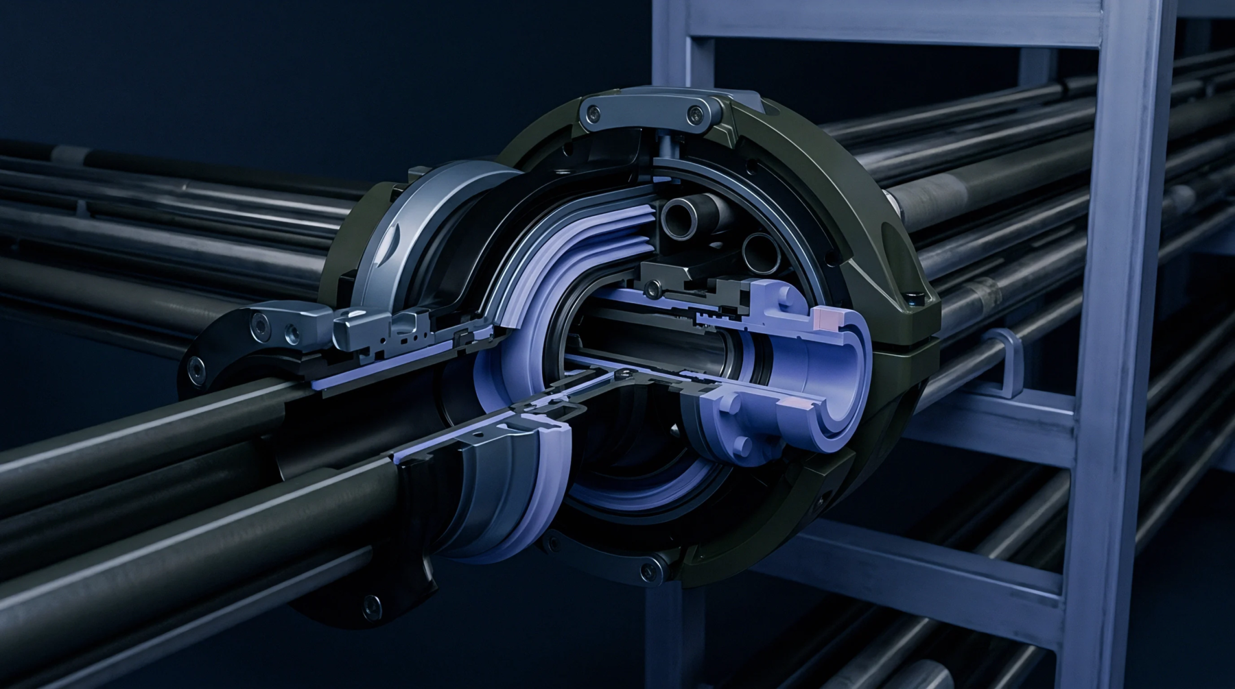
An electronic transducer placed within the mould tool generates a signal proportional to the molten resin force applied against the steel walls during an injection cycle. A cavity pressure sensor monitors the dynamic hydraulic force inside the tool to provide precise data regarding the filling and packing phases of a thermoplastic part. These devices translate physical compression into an electrical output that allows injection moulding controllers to adjust machine parameters during a production run.
By detecting variations in internal force, operators distinguish between successful fills and incomplete shots without inspecting the physical part. Accuracy relies on the physical connection between the transducer face and the polymer melt, meaning the probe must mount flush with the surface to avoid dead zones. Boundary conditions exist where extreme temperature fluctuations or improper installation shift the zero point, rendering the output unreliable for closed loop process control.
Moulding Integration
The transducer sits at a gate, a runner or a main cavity location to map the resin velocity and cooling rate of specific polymer sections. A cavity pressure sensor tracks the exact moment the plastic reaches the furthest wall point, allowing for an automatic switch from injection speed control to holding pressure control. High force spikes indicate overpacking, a condition that flashes the tool and adds unnecessary material cost to every cycle.
Conversely, low peak values signal underpacking, which leads to voids and dimension failure in the finished component. Resin rheology governs the signal shape, as higher melt flow rates produce smoother curves, while high glass fiber content creates sharper, erratic noise levels on the data trace.
Material Differentiation
Virgin resin exhibits predictable pressure curves because the molecular weight distribution remains constant across different lots from the supplier. Recycled materials or excessive regrind levels alter the viscosity, which changes the required holding time and the resulting pressure profile inside the tool. Moulders identify shifts in base material quality by comparing the historical integral of the pressure curve against current production batches.
A datasheet value for viscosity often assumes a stable, clean environment, yet a sensor captures the reality of the material as it moves through the cooling channels. Maintaining a consistent peak pressure value keeps dimensional shrinkage within tolerance, preventing the part from drifting outside of specifications due to raw material inconsistency.
Process Stability
Tooling maintenance demands periodic calibration of the electronic signals to ensure the internal readings match the actual force applied to the melt. A cavity pressure sensor provides a reliable audit trail for quality assurance, since the data trace forms a unique signature for every part produced. Differences in tool temperature or coolant flow rates appear as distinct shifts in the pressure curve, even when the injection machine settings remain fixed.
Successful manufacturing depends on linking the machine stroke to the actual state of the plastic inside the cavity, as reliance on external machine timers alone produces variability in the final part quality. Consistent signal output confirms the process remains within a tight, validated operating window.