Decoupled Moulding Control Using Real Time Cavity Pressure Feedback Architecture
Decoupled cavity pressure control decouples melt rheology from machine mechanics, fixing peak pressure to guarantee tight dimensional stability.


Split

Volumetric Fill and Machine Separations
In high-precision injection moulding, decoupling the fill phase from the pack and hold phase isolates machine hydraulics from polymer rheology. Viscosity fluctuates continuously. Steel defines part boundary.
Standard stroke-dependent position transfer transfers melt into the cavity until the screw reaches a set mechanical position. Machine position remains constant, yet resin viscosity variations cause cavity fill percentages to drift between ninety-four and ninety-nine percent prior to pack pressure application. Decoupled control transfers phase transitions based on actual melt state rather than screw displacement.
Separating the injection sequence into distinct physical phases eliminates hydraulic coupling errors. Phase one drives melt into the tool at controlled volumetric flow rates using closed-loop screw velocity control, filling roughly ninety-five percent of part volume. Phase two completes cavity filling and manages volumetric shrinkage through controlled packing pressure.
Phase three maintains structural integrity while the part freezes against the water-cooled tool wall. When machine control relies solely on screw position, a two percent drop in material melt flow index creates flash or sink marks, because the screw hits its switchover point while cavity resistance remains variable.
Pressure drops across runners. Polymer molecules align under shear forces during fast fill, altering local viscosity dynamically. In a un-decoupled process, hydraulic pressure spikes uncontrollably during the final two percent of volumetric filling, causing mold parting line deflection.
Decoupled methodology caps injection velocity to preserve uniform shear rates, holding hydraulic pressure in reserve until the cavity transitions into the packing state. Controlling this boundary prevents structural stress concentrations near the gate area.
Peak cavity pressure stability within plus or minus fifteen bar holds dimensional variance inside three micrometres across a fifty-thousand-shot production run in semi-crystalline resins.

Hydraulic Position Limits
Traditional injection presses rely on screw stroke transducers to switch from fill to pack control. Steel temperature shifts alter barrel dimensions, creating subtle leakage flow past the non-return valve check ring. Slippage across the screw flight changes the effective cushion volume on every shot.
A set transfer position of fifteen millimetres yields different filled volumes when check-ring seal timing varies by even ten milliseconds.
Position-based switchover fails to account for batch-to-batch polymer property changes. Virgin resin blended with regrind shifts thermal conductivity and shear response. Melt behavior governs density.
When higher viscosity material enters the barrel, hydraulic pressure rises rapidly to maintain velocity, causing the machine to hit hydraulic pressure caps before reaching the position setpoint. The process loses velocity control prematurely, creating short shots or density gradients across complex part geometries.
- Parting line flash occurs when peak hydraulic transfer pressure forces cavity walls apart prior to gate seal, leaving unwanted resin fins on parting surfaces.
- Uncompensated sink marks appear in heavy wall sections when melt shrinkage exceeds the volume supplied during position-restricted packing phases.
- Internal void formation arises from localized pressure drops in thick ribs where melt freezes before packing energy reaches nominal density thresholds.
- Dimensional drift develops across production shifts as oil viscosity drops in hydraulic lines, changing machine response times relative to screw position targets.
Process engineers overcome these mechanical limitations by migrating feedback sensors directly into the tool steel. Placing pressure monitoring elements inside the mold cavity captures the exact moment polymer reaches specific locations. This physical feedback replaces estimated screw work with measured cavity resistance.
The open question remains whether optical melt-front sensors can match the long-term mechanical reliability of piezoelectric pin arrangements in continuous production environments.

Diaphragm

Transducer Mechanics in Steel
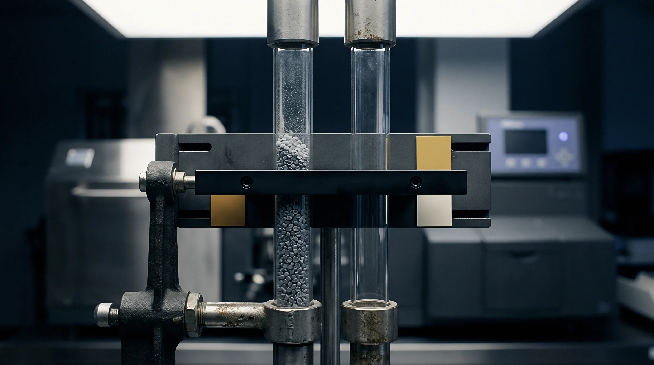
Real-time cavity pressure architecture relies on specialized sensor instrumentation installed within the tool structure. Piezoelectric quartz elements contain crystalline structures that generate electrical charge proportional to applied force. Direct transducers expose a hardened diaphragm directly to molten polymer inside the impression wall.
Indirect transducers sit behind ejector pins, measuring mechanical forces transferred through the pin body during cavity filling.
Diaphragm selection dictates signal integrity and tooling maintenance schedules. Direct quartz sensors eliminate pin friction errors, delivering accurate pressure curves even under high tool temperatures. They require precise wire-EDM pocket machining to align the sensor face flush with cavity walls.
An offset of ten micrometres creates a visible edge mark on show surfaces or induces local resin stagnation. Indirect sensors utilize existing ejector system geometry, protecting the sensitive transducer element behind standard ejector pins inside the support plate.
| Performance Parameter | Direct Quartz Piezoelectric | Indirect Strain Gage Pin Button |
|---|---|---|
| Data recorded under laboratory test conditions using PA66 resin with thirty percent glass fiber at 290 degrees Celsius melt temperature. | ||
Pin friction creates noise. Ejector pin clearance fit allows polymer flash to ingress into the pin channel over thousands of cycles. Accumulated resin increases sliding resistance, absorbing up to twenty percent of the force intended for the transducer button.
Signal calibration must account for mechanical drag along the pin length, requiring periodic zero-point resets during operation.

Signal Processing at Press Side
Electrical signals generated by quartz transducers arrive at charge amplifiers in the pico-Coulomb range. Signal timing alters weight. High-impedance cabling must route through protective conduits inside tool plates to prevent electromagnetic interference from machine heater bands and servo motors.
Amplifiers convert low-charge signals into zero-to-ten-volt analogue outputs or digital bus signals at sampling frequencies exceeding two kilohertz.
- Machining the transducer cavity pocket inside the ejector retaining plate according to drawing tolerances within five micrometres parallel alignment.
- Installing high-temperature wiring harnesses through milled plate channels, avoiding sharp bends that exceed the minimum twenty-millimetre bend radius limit.
- Mounting the load button transducer into the pocket, ensuring flush contact between button face and ejector pin base without mechanical preload binding.
- Connecting charge amplifier channels to machine controller interface cards using double-shielded low-noise coaxial cabling.
- Executing zero-point calibration sequence with tool at operating temperature prior to introduction of plastic melt into cavities.
Signal processing cards process pressure data in real time, comparing live curves against baseline template profiles stored in machine memory. When cavity pressure reaches a predetermined threshold, the controller sends a switchover interrupt directly to the hydraulic servo valve or electric injection drive. Response times under two milliseconds prevent over-pressurization.
Transducer calibration conducted at ambient shop floor temperature will deliver false pressure curves once tool plates reach thermal equilibrium during production runs.


Switchover

Real Time Feedback Control Architectures
Transitioning from velocity control to pressure control using direct cavity pressure feedback establishes tight process stability. Real-time feedback overrides standard screw position limits when cavity pressure reaches the specified target value. The press instantly drops screw speed, transferring to hold pressure tailored to match the material solidification curve inside the cavity.
Cavity filling demands speed. This dynamic control loop compensates for continuous variations in melt viscosity without human operator intervention.
Dynamic switchover utilizes pressure transducers located at key locations inside the mold. Position near the gate detects fill arrival early, controlling primary velocity termination. Position near the end of fill detects complete volumetric fill, preventing short shots in thin-walled sections.
Dual-sensor architectures combine both signals, triggering switchover when the end-of-fill transducer registers a sharp pressure rise indicating cavity completion.
Process repeatability improves by an order of magnitude when switchover relies on end-of-fill cavity pressure rather than screw position or hydraulic line pressure.

How Does Peak Pressure Feedback Compensate Viscosity Shifts?
Viscosity decreases when barrel thermal bands drift high or material shear increases. Low viscosity melt flows faster through runners, filling the cavity prematurely under standard velocity profiles. Peak pressure control detects this rapid pressure buildup instantly.
The system executes switchover ahead of position targets, avoiding flash along mold parting lines. Hydraulic position misses viscosity shifts. Real-time feedback compensates for property variations across different resin lots automatically.
| Control Strategy | Switchover Signal Origin | Weight Variance Band | Viscosity Shift Response |
|---|---|---|---|
During material processing, lot-to-lot melt flow index variations alter fill resistance substantially. Higher viscosity resin builds pressure slowly. The feedback controller holds injection velocity longer until cavity pressure reaches the precise setpoint, ensuring complete filling before packing begins.
Maintaining constant peak cavity pressure locks in physical part dimensions regardless of raw material flow characteristics.

Decoupled Control Architecture Variants
Advanced control architectures split the injection process into distinct closed-loop segments controlled by different sensor inputs. Decoupled Strategy II uses screw speed control for fill, switching to hydraulic pressure for pack, with cavity pressure acting as an abort safety threshold. Decoupled Strategy III uses cavity pressure directly to trigger switchover and modulate holding pressure profiles throughout the cooling phase.
- Set pressure threshold switchover triggers transfer to pack the instant cavity sensor voltage exceeds a calibrated pressure baseline value.
- Decelerated pressure curve profiling steps down screw speed in increments as cavity pressure approaches target limits, softening hydraulic shocks.
- Active peak cavity pressure regulation modulates hydraulic pack valves dynamically to hold cavity pressure constant until gate freeze occurs.
- Volumetric pressure integration calculates total force over time curves, adjusting hold duration to match calculated volumetric contraction rates.
Configuring dynamic setpoints requires accurate determination of gate freeze timing. If packing pressure drops before the gate solidifies, polymer flows back out of the cavity into the runner system, causing dimensional sink. Improper transducer placement downstream of thick wall features results in delayed signal transmission, causing severe mechanical over-packing, damaged parting line steel, and permanently deformed tool cores.

Variance

Thermal Drift and Rheological Shift
Ambient shop temperatures and cooling water fluctuations induce significant drift in molding process windows over extended production shifts. Thermal drift changes volume. Tool steel expands as internal temperatures rise, altering impression volumes by fractional percentages.
Heat exchanger efficiency drops during afternoon shifts, raising oil temperatures inside hydraulic reservoirs and delaying valve response times by several milliseconds.
Resin lot switches introduce immediate rheological variation. Recycled content, colorant masterbatch additions, and ambient humidity levels alter viscosity profiles significantly. Standard presses running open-loop position control produce dimensional drift exceeding drawing tolerance bands when processing hygroscopic materials like polyamide or polycarbonate.
Cavity pressure feedback actively counteracts these variables by adjusting machine work output shot by shot.
DIN 16742 Grade TG4 dimensional tolerances can only be sustained on technical polymers across multi-day runs when peak cavity pressure variance remains below one percent.

Process Window Qualification Parameters
Establishing a validated process window requires systematic experimentation across polymer viscosity extremes. Engineers run rheology studies to identify the flat region of the viscosity versus shear rate curve, selecting injection speeds that minimize viscosity sensitivity. Tool trials establish upper and lower limits for cavity pressure setpoints by identifying conditions that produce flash or short shots.
- Viscosity curve determination establishes minimum shear rates required to achieve stable melt flow without inducing thermal degradation.
- Cavity pressure transfer study defines the target switchover bar value needed to achieve ninety-eight percent volumetric fill under velocity control.
- Gate seal verification curve tracks part mass against hold time variations to confirm complete gate freezing prior to hold pressure release.
- Process window boundary map plots hold pressure against melt temperature to identify operational zones meeting drawing tolerances.
Molding suppliers often claim that machine hydraulic repeatability renders cavity pressure instrumentation unnecessary for nominal part geometries. This argument ignores long-term mechanical wear inside injection units, check ring erosion, and subtle ambient humidity changes that alter resin behavior over time. Relying purely on press repeatability without internal mold cavity telemetry leaves production runs vulnerable to undetected dimensional drift.

Yield

Capital Investment and Amortisation Metrics
Integrating real-time cavity pressure feedback architecture demands upfront tooling expenditure for sensor hardware, pocket machining, and controller interface integration. Tooling cost rises initially. A four-cavity technical tool requires four individual pressure transducers, specialized wiring harnesses, multi-channel charge amplifiers, and signal integration modules.
These additions increase initial tooling budgets by eight to twelve percent.
Investment payback accrues through immediate scrap reduction and cycle time optimization. Real-time feedback eliminates dimensional sorting requirements, lowers startup waste, and allows engineers to compress holding times to the exact millisecond of gate freeze. Scrap rates drop rapidly.
Eliminating two percent scrap on a high-volume auto component pays back sensor hardware costs within the first three months of continuous production.
| Cost Component | Standard Tooling Setup | Cavity Pressure Instrumented Setup |
|---|---|---|
| Amortisation calculated on annual volume of 500,000 units using engineering grade PBT resin at 3.50 USD per kilogram. | ||
Real-time cavity feedback stabilizes dimensions across automated assemblies. Downstream automated insertion processes stall when part dimensions deviate by more than fifty micrometres. Consistent part geometries ensure reliable robot pick-and-place operations, preventing costly automated assembly line stoppages and manual rework interventions.

Commercial Quality Agreements and Tolerance Grades
Sourcing agreements for precision plastic parts specify statistical process capability targets alongside drawing dimensions. Standard contracts demand capability metrics where process performance indices exceed 1.33 for critical characteristics. Achieving these figures consistently across multi-cavity tools requires real-time cavity pressure monitoring and continuous automated part sorting using machine rejection gates.
Real-time cavity pressure instrumentation transforms process control from reactive post-mould inspection to predictive quality assurance at the point of part formation.
Quality assurance contracts stipulate that production lots manufactured while cavity pressure tracking exceeds validated baseline limits must be automatically segregated. Modern press controllers execute automatic reject chute routing when pressure peak signals cross control boundaries. Standard supply agreements enforce DIN 16742 Tolerance Group TG3 for critical optical and mechanical interface dimensions only when verified cavity pressure records accompany each delivered production lot dossier.