Establishing Press Side Fill Balance Protocols for Multi Cavity Injection Moulding Tooling
Press-side fill balance protocols decouple injection velocity from hold pressure using short shot weight analysis to equalize cavity fill within 5% balance.

Shorts
Structural consistency and dimensional stability in multi-cavity tooling depend on uniform volumetric filling during the primary injection stage. In theory, a balanced runner network offers equal flow resistance through every branch, delivering polymer to each gate at the exact same moment. In practice, runner machining tolerances, steel temperature gradients, and non-linear shear heating disrupt that balance.
Short shot evaluation at the press isolates this filling phase before packing pressure ever takes effect, showing whether cavity variations stem from runner geometry or thermal differences.
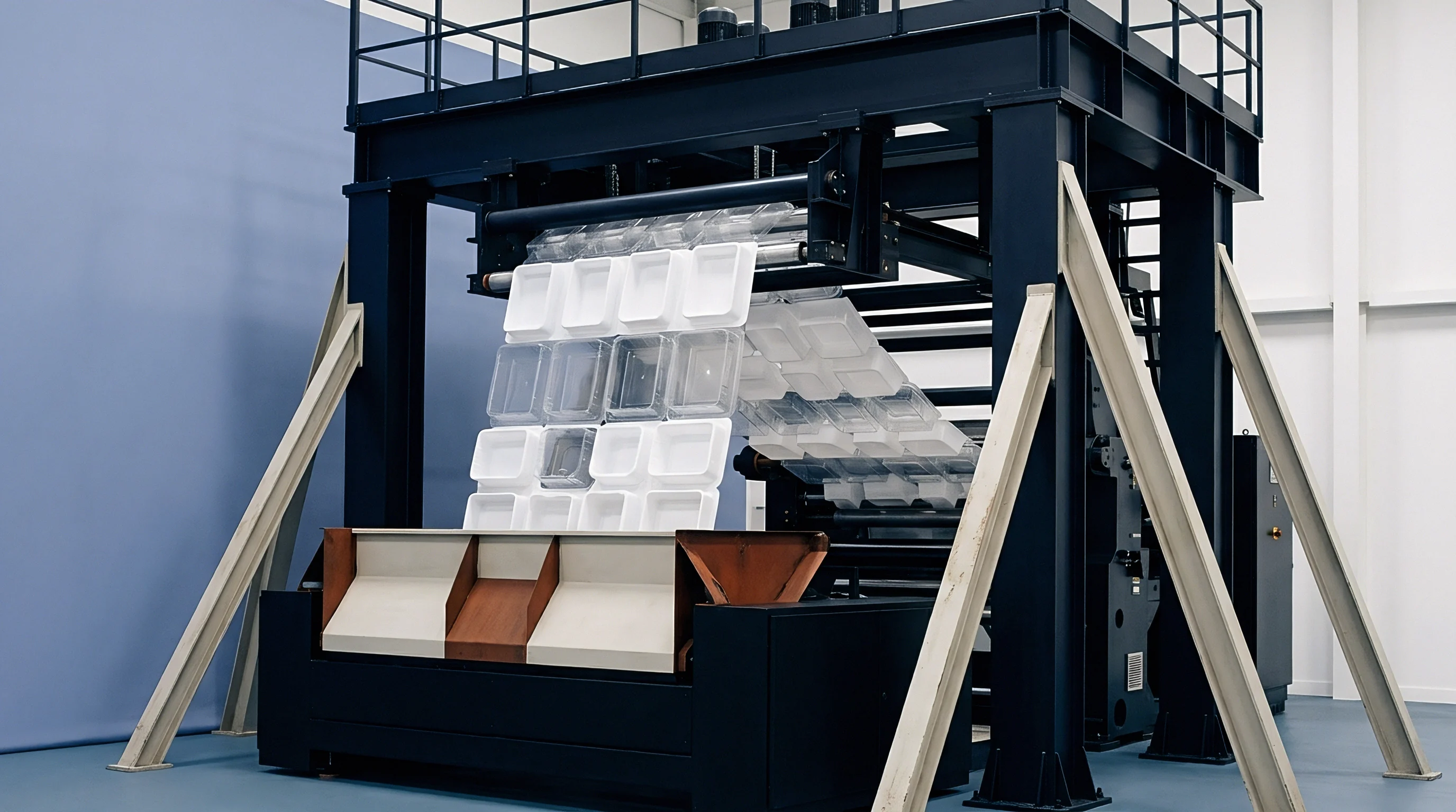
Evaluating fill balance requires cutting off second-stage hold pressure to isolate first-stage velocity control. The technician sets the transfer position by screw displacement so the injected volume reaches roughly eighty percent of part capacity. With hold pressure zeroed and melt temperature held steady, the machine produces frozen short shots that capture the raw melt progression.
Weighing individual partial mouldings from one shot reveals which cavities lead or lag, and dividing the lightest cavity weight by the heaviest yields the numerical fill balance percentage.
Equalizing melt velocity through identical gate dimensions prevents localized over-packing before the hold phase begins.
Take an eight-cavity tool running polybutylene terephthalate electrical connectors with a 1.20 millimetres nominal wall thickness. At an eighty percent volumetric fill, individual part weights across cavities one through eight come out to 2.12 grams, 2.14 grams, 2.45 grams, 2.48 grams, 2.11 grams, 2.13 grams, 2.46 grams, and 2.47 grams. Dividing 2.11 by 2.48 gives an 85.08 percent fill balance.
High shear rates developed at upstream runner splits drop the melt viscosity heading into the inner cavities, so they fill well ahead of the outer positions despite identical runner lengths.
Under normal production conditions, that kind of imbalance spreads defects across the mould layout. Fast-filling cavities spend too long under pack pressure, while slow cavities barely fill out before their gates freeze shut. The early cavities end up flashing, while the under-filled ones develop sinks and internal voids.
- Flash Formation occurs when early-filling cavities see excess hydraulic pressure before switchover, forcing parting line steel to separate slightly.
- Sink Marks And Voids develop in lagging cavities when early gate freeze cuts off pack pressure before volumetric shrinkage settles.
- Dimensional Variance tracks uneven cavity pressure peaks, leaving fast-filling cavities with lower shrinkage than slower ones.
- Part Warpage occurs when density differences between cavities set up uneven internal stress patterns during cooling.
- Internal Stress Concentration builds near the gates of over-packed cavities, raising the risk of environmental stress cracking in the field.
Quality criteria for fill balance typically fall into tiers based on required part tolerances. Running higher injection speeds can offset thermal losses along runner walls, which often shifts the balance profile significantly from one velocity setting to the next.
| Tolerance Grade | Target Fill Balance (%) | Max Weight Delta (%) | Primary Defect Risk | Correction Method |
|---|---|---|---|---|
| DIN 16742 TG3 | 95.0 to 98.5 | 1.5 | Tight tolerance shift | Runner steel safe erosion or melt flipper inserts |
| DIN 16742 TG4 | 90.0 to 94.9 | 3.0 | Localized sink marks | Gate dimension tuning and nozzle tip adjustment |
| DIN 16742 TG6 | 82.0 to 89.9 | 5.5 | Parting line flash | Injection speed adjustment and thermal profiling |
| Commercial Grade | 75.0 to 81.9 | 8.0 | Short shots and voids | Secondary packing pressure compensation |
Cranking up hold pressure to hide a fill imbalance only masks the underlying geometric or thermal defect while fatiguing the mould steel. Forcing material into slow cavities by over-packing the fast ones causes uneven plate deflection across parting surfaces. The result is parting line flash, hobbed steel around gates, and scrap spikes the moment resin viscosity shifts between lots.

Manifold
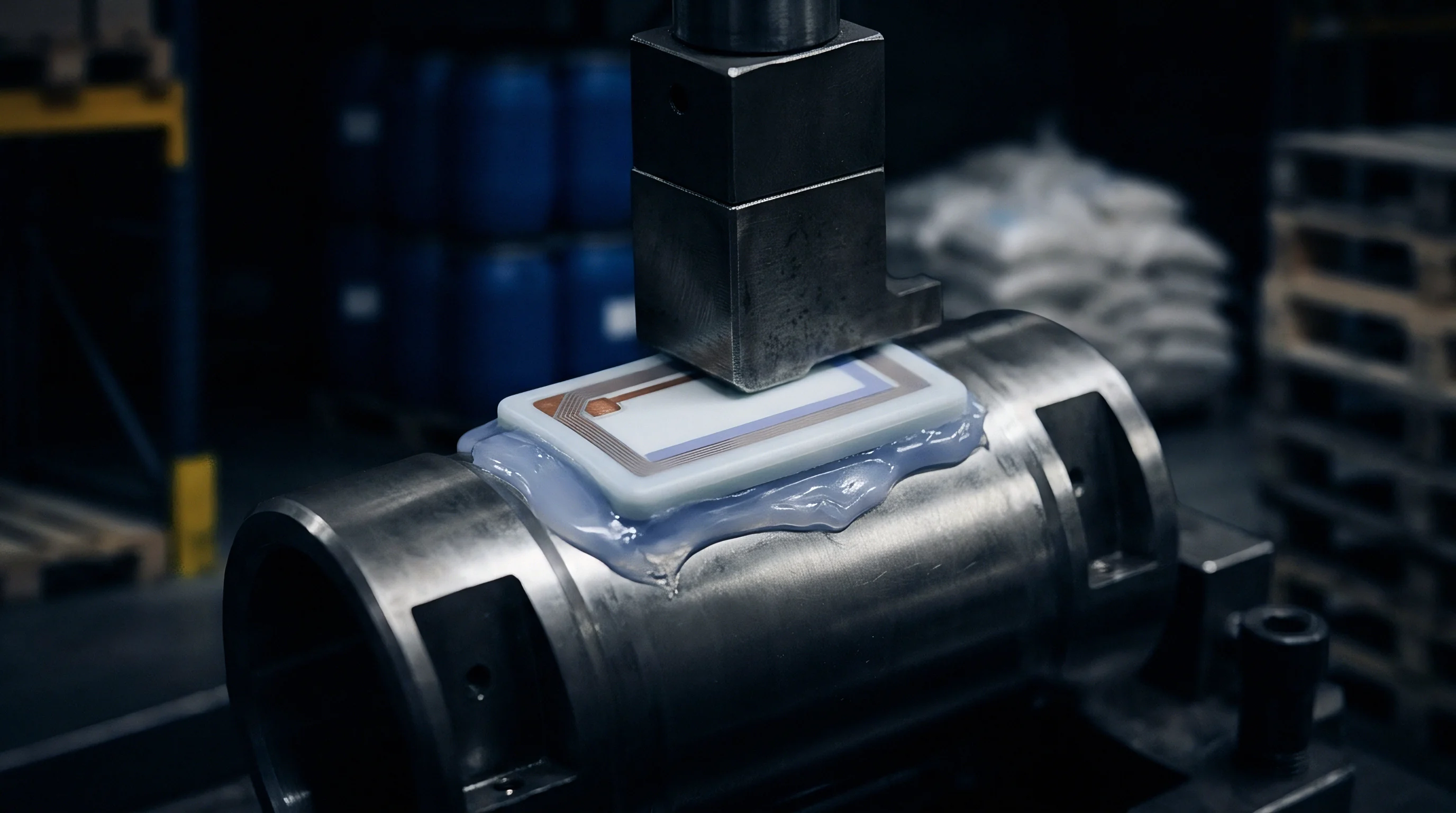
Laminar flow through a runner channel creates an uneven shear stress profile across the melt. High shear along the channel walls produces localized viscous heating, wrapping a hot, low-viscosity outer skin around a cooler, stiffer core. When that non-uniform stream hits a tee-split, the shear-heated outer layer diverts down one branch while the cooler core heads into the other.
Runner layouts that appear geometrically symmetrical then behave asymmetrically because the thermal history splits unevenly at each branch.

Do High Viscosity Polymers Exacerbate Shear Induced Imbalance across Branch Splits?
Shear-sensitive materials like polycarbonate and acrylonitrile butadiene styrene show pronounced fill swings across runner branches. Pushing injection speed increases wall shear stress, widening the temperature spread across the channel cross-section. Without runner features that invert this shear profile, outer cavities end up receiving distinctly cooler melt.
Melt rotation devices, such as commercial melt flippers, roll the hotter perimeter layer into the center of the flow channel before the next branch, evening out hydraulic resistance.
A ten-degree Celsius thermal difference across runner branches reduces local polymer viscosity by up to eighteen percent in amorphous resins.
Hot runner manifolds introduce another layer of thermal variation that compounds shear effects. Cartridge heaters and manifold geometry create uneven temperature fields, particularly if drop nozzles drift out of calibration. A single nozzle running just two degrees higher than adjacent drops drops local viscosity enough to accelerate flow, either hiding or worsening the underlying runner imbalance.
| Runner Configuration | Shear Rate at Wall (1/s) | Core to Wall Temp Delta (°C) | Viscosity Variation (%) | Cavity Fill Delta (%) |
|---|---|---|---|---|
| Standard H-Pattern Cold Runner | 8,200 | 14.2 | 22.5 | 12.4 |
| H-Pattern with Melt Rotation Inserts | 8,150 | 2.1 | 3.8 | 1.8 |
| Naturally Balanced Hot Runner (Standard) | 12,400 | 18.6 | 28.1 | 15.2 |
| Hot Runner with Tip Thermal Control | 12,350 | 3.4 | 4.2 | 2.1 |
Physical tooling adjustments meant to balance flow demand exact measurements of runner diameters and gate lands. Relieving runner steel on lagging cavities offers a direct mechanical fix, but changes the local shear rate and can throw balance off again whenever raw material viscosity varies.
- Melt Flipping Inserts reposition shear-heated outer melt layers to the channel center, equalizing thermal distribution ahead of downstream splits.
- Steel Safe Gate Tuning increases gate depth in slow-filling cavities by increments of 0.02 millimetres until volumetric parity lands within specification.
- Zoned Manifold Heating allows localized thermal offsets along distribution blocks to compensate for fixed cooling losses near plate edges.
- Rheological Runner Resizing alters secondary branch diameters based on non-Newtonian flow simulation rather than simple geometric symmetry.
Hot runner manifolds are often assumed to self-correct fill variations once production reaches steady-state thermal equilibrium, but thermal shifts rarely compensate for shear-induced distribution imbalances, leaving outer cavities starved during fast filling phases.

Decoupling
Separating primary fill from the packing stage is central to scientific moulding practices. Under a decoupled moulding setup, injection velocity remains constant throughout filling, letting the screw act as a true positive-displacement ram. Dialing in a speed on the flat portion of the resin’s viscosity-versus-shear-rate curve desensitizes cavity fill to minor batch-to-batch material shifts.
Generating that curve requires measuring effective viscosity across stepped injection speeds until shear thinning flattens out.
Operating at higher injection speeds helps dampen fill variations across multi-cavity moulds. Plotting relative viscosity against shear rate pinpoints the threshold where viscosity stops dropping steeply. Running the press within this plateau stabilizes shot-to-shot fill balance, requiring only a systematic velocity step study while tracking fill times and peak hydraulic pressures.
ISO 294-1 mandates holding injection velocity within five percent of setpoint to maintain valid mechanical specimen shrinkage comparisons.
Carrying out a balance study on the press requires a consistent, repeatable procedure, running through each verification step without shortcuts.
- Purge barrel and verify melt temperature using an insulated wire pyrometer probe inserted directly into the molten mass.
- Set switchover position to transfer from velocity control to pressure control at ninety-five percent of total part volumetric capacity.
- Zero hold pressure and hold time to ensure parts represent volumetric filling performance without packing assistance.
- Collect five consecutive partial shots at maximum machine injection velocity, discarding the first two shots to establish thermal stability.
- Number partial parts according to cavity position and weigh each sample on an analytical scale precise to 0.001 grams.
- Calculate mean mass and percentage deviation for every cavity position using the lightest and heaviest values measured.
- Repeat fill balance testing across five incremental injection speeds to plot velocity impact on filling distribution.
- Select the injection velocity profile that minimizes fill weight spread while remaining below the maximum tonnage limit.
Maintaining an adequate cushion prevents voids and sinks by ensuring hydraulic pressure transfers into the cavity steel rather than bottoming out the screw stroke. At the same time, machine dynamic response dictates switchover precision; sluggish valve response creates inertial melt overrun that disguises the tool’s true cavity flow balance.
Centering process parameters within this stable shear window keeps fill balance inside acceptable limits, even as raw material lots fluctuate.

Transducer
In-cavity pressure measurement gives direct physical data from within the tool steel, eliminating guesswork based on hydraulic readouts. Piezoelectric sensors placed behind ejector pins follow the stress rise as melt fronts pass the gate and reach cavity extremities. Comparing these peak fill pressures highlights flow delays and real-time volumetric balance, while pressure decay curves mark exact gate freeze timing across individual cavities.
Cavity sensors capture localized variations that machine-level controllers never see. Continuous tracking reveals subtle thermal and mechanical shifts as production runs across multiple shifts.
- Piezoelectric Sensors detect dynamic force changes at cavity walls with sub-millisecond response times, charting melt front arrival with precision.
- Strain Gauge Buttons provide cost-effective pressure tracking well suited for routine monitoring of packing consistency across cavities.
- Multi-Channel Charge Amplifiers convert electrostatic charge signals into calibrated voltage traces scaled to peak cavity bar pressure.
- Data Acquisition Software overlays cavity pressure curves in real time, catching any position that drifts outside set pressure limits.
These signals make automated part reject sorting straightforward at the press. If a hot runner nozzle tip cools, peak pressure in that specific cavity drops at once. Diverter chutes then separate parts from that cavity until temperatures recover, keeping out-of-spec components out of finished packaging.
Matching peak cavity pressures across all positions generally requires balancing gate geometry alongside manifold drop temperatures. Cold slugs or degraded polymer particles lodged in gate lands also spike hydraulic resistance, throwing off pressure readings and mimicking permanent tool defects.
Whether automatic, sensor-driven pack pressure regulation can completely overcome physical runner imbalances without locking in uneven residual stresses remains a subject of ongoing debate in precision moulding.
Ledger
Tool economics depend on running every cavity within nominal cycle limits without piling up scrap. An unbalanced mould burns machine hours and resin because cooling times must be stretched just to freeze the over-packed gates in faster cavities. That extra pack also packs on unnecessary weight.
On an eight-cavity tool running polyolefins, even a three percent fill imbalance pushes up resin costs over a year simply through excess plastic pushed into early-filling parts.
Sizing up the actual financial loss requires looking at resin waste, added cycle seconds, and press rates over planned volumes. Take an eight-cavity mould producing a 12.0-gram polypropylene housing on a 15.0-second cycle across 500,000 cycles annually. If an unbalanced condition creates a seven percent weight spread, it packs an extra 0.42 grams into four cavities on every shot while adding 1.8 seconds of cooling time just to seal the gates.
At $2.10 per kilogram for material and $65.00 per machine hour for press time, those small increments accumulate rapidly.
| Cost Parameter | Balanced Tool (2% Spread) | Unbalanced Tool (7% Spread) | Annual Variance |
|---|---|---|---|
| Resin Mass per Shot (g) | 96.00 | 97.68 | +840 kg resin |
| Annual Resin Cost ($) | $100,800 | $102,564 | +$1,764 |
| Cycle Time (s) | 15.0 | 16.8 | +250 machine hours |
| Press Operating Cost ($) | $135,416 | $151,666 | +$16,250 |
| Scrap Rate (Cpk | 0.3% | 4.2% | +19,500 bad parts |
| Scrap Financial Loss ($) | $756 | $10,584 | +$9,828 |
| Total Annual Run Cost ($) | $236,972 | $264,814 | +$27,842 |
Tooling procurement agreements need clear fill balance criteria alongside standard dimensional tolerances prior to steel acceptance. Signing off on a multi-cavity tool solely on finished part dimensions allows toolmakers to mask flow imbalances by modifying individual cavity inserts, producing components with non-interchangeable spare tooling.
Under DIN 16742 qualification guidelines, sign-off on multi-cavity balance requires volumetric fill variation to stay within five percent across all cavities at switchover under baseline scientific moulding settings. Once the mould reaches thermal equilibrium ~ typically taking twenty minutes ~ technicians verify balance across three distinct injection speeds before approving final tool acceptance.