Piezoelectric Cavity Pressure Sensor Setup in Micro Injection Moulding
Direct piezoelectric cavity pressure sensing in micro injection moulding requires sub-micron bore tolerances, rigid preloading, and active thermal drift compensation.


Scale
Parts weighing under fifty milligrams with wall thicknesses below two hundred micrometres demand millisecond melt control during the injection cycle. Micro-moulds operate under extreme thermal cycles. Traditional hydraulic machine pressure transducers mounted in the injection cylinder or nozzle measure hydraulic oil compression or screw movement, but these signals fail to reflect true conditions inside tiny mold cavities.
Frictional losses along the runner system, melt viscosity fluctuations, and rapid thermal chilling at thin walls attenuate hydraulic pressure transfer. Cavity pressure monitoring places sensor interfaces directly at or near the resin fill area, capturing actual melt behavior as plastic enters, fills, and packs the tool steel.
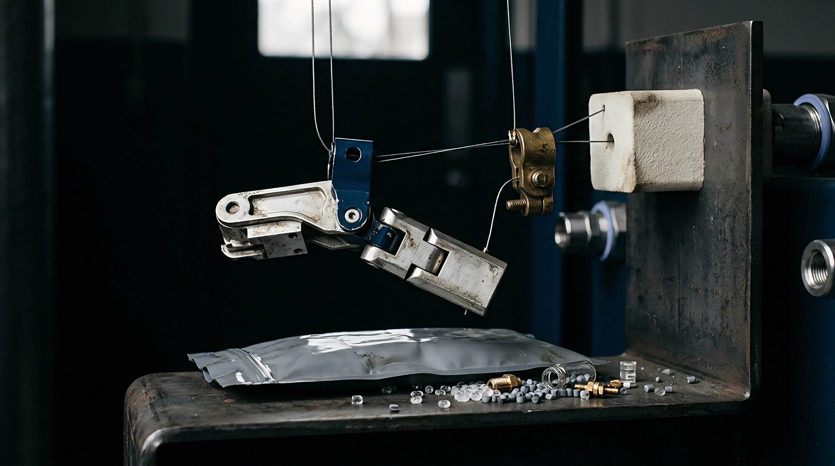
Micro Injection Tooling Boundaries
Shot volumes under one cubic centimetre mandate precise tool construction to manage rapid resin solidifications. The physical volume of a micro-cavity limits sensor placement. Standard industrial pressure transducers with six-millimetre or eight-millimetre sensor tip diameters cannot fit into micro-cavities without overrunning part features, core pins, or cooling channels.
Toolmakers working on micro-moulding projects encounter strict spatial limitations within tool inserts. Installing pressure sensors into these micro-tools involves managing clearances where an ejector pin or sensor tip tip face spans a significant portion of the total component surface area. Direct measurements isolate cavity pressure.
When selecting transducer locations, the cavity geometry determines whether direct or indirect force sensing is viable. Direct transducers position quartz crystal tip faces flush with the cavity wall, coming into contact with molten resin. Indirect transducers sit behind dedicated ejector or measuring pins, recording force transferred through the steel pin during filling and packing.
In micro-moulding, small cavity dimensions frequently force the selection of indirect measuring pins with tip diameters down to zero-point-four millimetres. Wall friction attenuates transferred forces.
A four-tenths millimetre measuring pin subjected to one thousand bar cavity pressure transfers twelve-point-six Newtons of axial force to the underlying piezoelectric crystal.

Force Transmission Physics at Sub-Millimetre Interfaces
Load application across tiny contact surfaces creates severe mechanical stress concentrations within hard tool steel. Micro-injection pressures routinely reach one thousand five hundred to two thousand five hundred bar to force polymer melt through thin runner systems before freezing occurs. On a measuring pin with a tip diameter of zero-point-five millimetres, a cavity melt pressure of two thousand bar generates an axial force of thirty-nine-point-three Newtons.
Transducer charge output scales directly with force rather than pressure. Piezoelectric quartz crystals generate an electrical charge in response to applied mechanical load, measured in picocoulombs per Newton.
Pin bending and bore friction significantly alter force transfer in micro-tools. When high-pressure melt hits the end face of a sub-millimetre pin, any axial misalignment or slight clearance imbalance causes the pin to flex against the bore wall. Pin binding corrupts cavity pressure curves.
Lateral contact forces generate frictional drag along the pin guide length, preventing a portion of the force from reaching the piezoelectric sensor located behind the pin base. Tool design must incorporate hardened guide bushings with polished internal walls and diametral clearances restricted to two to four micrometres to minimize force losses while preventing polymer melt flash from entering the pin bore.
Improper pin sizing or incorrect insertion placement causes localized melt flash and structural pin bending, leading to unrecorded pressure spikes, flash-locked mold inserts, and immediate tool breakage.


Crystal
Piezoelectric quartz transducers convert applied compression into proportional electrical charge through precise atomic lattice deformation. Quartz crystals output minimal electrical charge. Unlike strain gauge transducers that rely on Wheatstone bridge circuits requiring external excitation voltages, piezoelectric sensors generate their own electrical charge under mechanical pressure.
This self-generating property makes quartz elements suitable for dynamic cavity pressure measurement in micro injection moulding, where rapid pressure fluctuations occur over time intervals shorter than fifty milliseconds.

Direct Transducers versus Indirect Transfer Pins
Measuring melt compression directly at the cavity wall eliminates intervening mechanical components. Direct piezoelectric sensors integrate the sensing crystal and metallic diaphragm into a single compact housing installed flush with the cavity surface. Micro-scale direct sensors feature front diameters as small as one-point-zero millimetres.
Direct sensors occupy prime cavity steel. High thermal stability and structural rigidity allow direct transducers to record immediate cavity pressure changes without mechanical lag.
Indirect sensor systems position a piezoelectric force washer or button transducer behind a movable steel pin. The pin acts as an intermediate transmitter, conveying melt pressure forces from the cavity interior to the sensor element housed deeper in the mold base. Indirect configurations accommodate sub-millimetre sensing surfaces by utilizing custom ejector pins ground to match micro-part contours.
Mechanical friction along the pin guide length reduces transmitted force, requiring electronic compensation or empirical calibration factors during processing.
The following set identifies primary failure modes occurring within indirect force transmission pin assemblies in micro injection tooling:
- Friction Attenuation arises when high-pressure resin forces sub-millimetre pins against bore walls, creating side loads that reduce the axial force delivered to the sensor crystal by up to thirty percent.
- Melt Ingress Flash develops when diametral clearances exceed three micrometres, permitting thin polymer films to enter the pin gap and jam mechanical motion during high-speed injection.
- Preload Relaxation occurs over extended production cycles as clamping forces and thermal expansion compress internal mechanical interfaces, causing baseline signal drift.
- Pin Tip Plastic Deformation happens under repeated two-thousand-bar pressure cycles when tool steel hardness falls below fifty-eight HRC, mushrooming the pin end face and causing cavity mark defects.

Melt Flow Sensitivity and Temperature Transient Errors
Polymer melt entering the tool cavity creates an immediate localized thermal surge against all metallic surfaces. Quartz crystals exhibit pyroelectric effects, generating false electrical signals when subjected to sudden surface temperature jumps. Direct sensors with thin metallic front diaphragms experience rapid heating during the filling phase, expanding the housing and creating internal thermal stresses that mimic pressure charge output.
Thermal transients introduce false pressure spikes.
Indirect sensor arrangements mitigate thermal transient errors by isolating the transducer crystal deep within the tool plate, away from direct contact with molten resin. The measuring pin conducts heat slowly along its length, shielding the crystal element from rapid temperature changes during the millisecond injection stroke. Thermal insulation disks installed between the pin base and sensor button further isolate the transducer from thermal expansion effects.
| Parameter | Direct Piezoelectric Sensor | Indirect Sensor via Measuring Pin |
|---|---|---|
| Front Tip Diameter | 1.0 mm to 2.5 mm | 0.4 mm to 1.0 mm pin tip |
| Sensitivity Range | -9.0 pC/bar to -25.0 pC/bar | -2.5 pC/N to -4.1 pC/N |
| Thermal Transient Shock Sensitivity | High (direct melt contact) | Low (isolated behind ejector pin) |
| Installation Steel Footprint | Requires 12 mm to 16 mm bore depth | Requires remote mounting cavity in ejector plate |
| Mechanical Pin Friction Interference | Zero friction loss | 12% to 28% force attenuation from wall friction |
Transducer manufacturers frequently argue that signal drift and baseline jump during rapid cycle micro-moulding stem entirely from customer failure to maintain ambient amplifier humidity and improper electrical grounding rather than inherent pyroelectric sensitivity in miniature quartz elements.
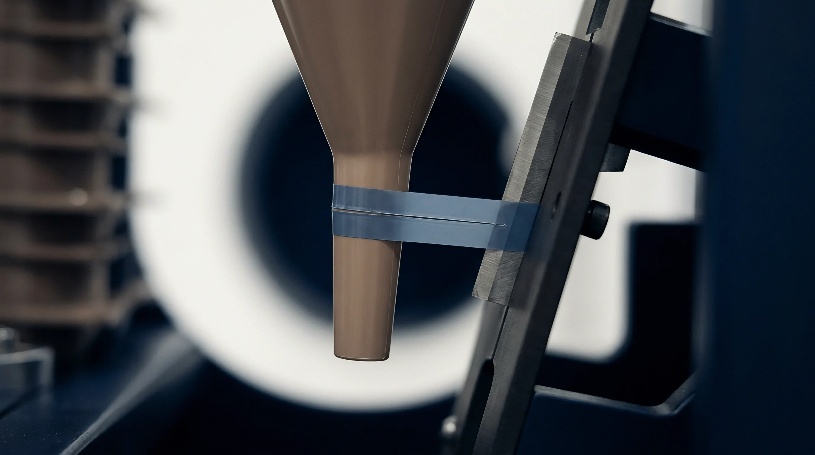
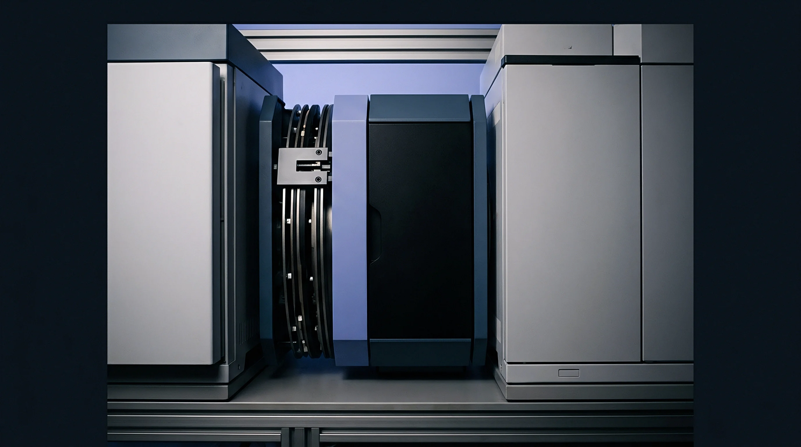
Mount
Integrating pressure sensors into small tool inserts requires accurate bore dimensions and polished land surfaces. Mechanical preload determines sensor linearity. Piezoelectric quartz elements exhibit non-linear electrical response when loose in their mounting bore.
Applying controlled mechanical compression during sensor installation pre-loads the internal quartz disks into their linear operating range, establishing consistent picocoulomb charge output per unit force.
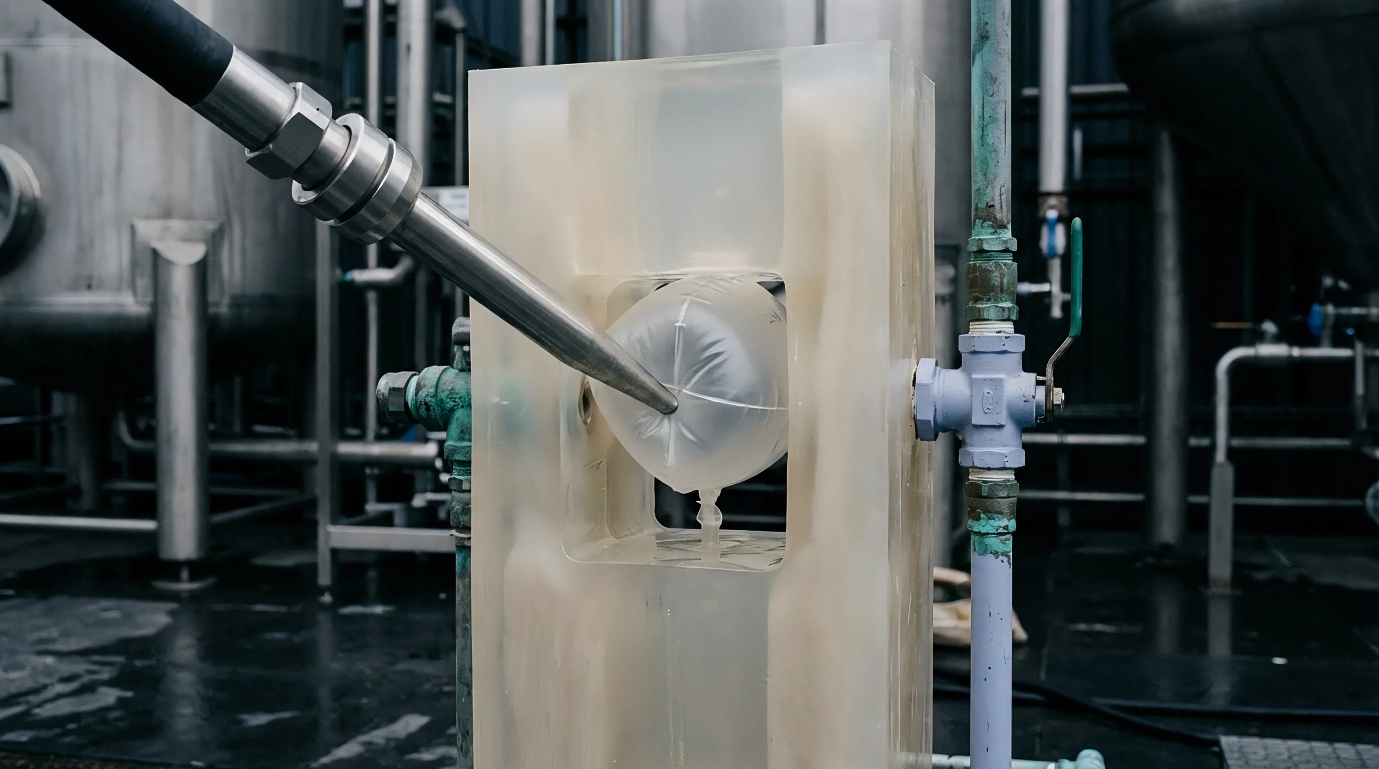
Bore Geometry and Tool Machining Tolerances
Sensors installed in mold inserts demand cylindrical holes with diametral clearance held within five micrometres. Tight machining tolerances prevent melt flash. Precision reaming or electrical discharge machining creates bores with surface roughness values below Ra zero-point-two micrometres.
The seating face at the bottom of the sensor bore must be machined perpendicular to the bore axis within zero-point-zero-zero-five millimetres. Non-parallel seating faces exert uneven bending moments on quartz crystals, inducing severe measurement errors or cracking delicate ceramic insulation rings under clamp pressure.
For direct sensors, the front tip must rest flush with the mold cavity wall. A protruding sensor tip leaves impression marks on micro-mouldings, interfering with assembly fit and part function. A recessed sensor creates a dead space where polymer melt collects, degrades, and forms flash rings that hinder part ejection.
Toolmakers adjust spacer rings or micrometer threaded sleeves behind the transducer housing to align the sensor face flush within plus or minus two micrometres relative to surrounding tool steel.
The sequence below defines the procedure for installing a direct piezoelectric transducer into a hardened micro-cavity steel insert:
- Machine the transducer mounting bore using wire electrical discharge machining to achieve a diameter tolerance of H7 and surface finish below Ra zero-point-two micrometres.
- Lap the bottom seating shoulder flat to guarantee ninety-degree perpendicularity against the bore centerline.
- Clean all bore surfaces using ultra-pure isopropyl alcohol to eliminate machining oils, metal particles, and ambient dust.
- Insert the transducer into the bore by hand without applying rotational force to avoid galling polished metallic contact faces.
- Thread the hollow lock nut into the insert sleeve using a calibrated torque wrench set to specified manufacturer tightening limits.
- Measure sensor tip flushness using an optical profilometer or dial indicator to verify protrusion remains within plus or minus two micrometres.

Threaded Sleeve Torque and Preload Compression Verification
Applying axial force to piezoelectric elements ensures stable voltage readings under dynamic pressure cycling. Threaded mounting sleeves secure transducers within steel tool cavities. Tightening the sleeve compresses internal spring washers or elastic housing zones, establishing a defined mechanical preload force, typically between ten and twenty Kilonewtons for standard sensors, or zero-point-five to two-point-five Newton-metres torque for miniature threaded variants.
Steel deflection alters sensor preloads. Clamp forces applied by the injection press compress cavity inserts during mold closure. If tool steel deforms around the sensor mounting bore, the installed preload shifts, distorting calibration curves.
Mold designers position sensor bores in rigid tool locations away from unsupported insert bridges, slide guide mechanisms, or thin cooling channel walls that flex under clamp tonnage.
Standard tool sign-off clauses under DIN 16742 Section 4.2 stipulate that cavity sensor alignment tolerances remain within plus or minus two micrometres of flush under maximum clamp load, transferring all repair costs to the mold builder if flash occurs during acceptance trials.

Where Does Charge Leakage Interfere with Micro Moulding Traces?
Electrical signals generated by quartz elements under peak load measure in the range of tens of picocoulombs. Insulation resistance across the sensor terminal, cable connector, and charge amplifier input must exceed ten to the thirteenth Power Ohms to prevent electrical charge from leaking to ground during measurement cycles. Moisture leaks ruin piezoelectric insulation.
Micro-moulding tools frequently run mold temperature control fluids above one hundred degrees Celsius to maintain resin flow through thin micro-channels. Water vapor or cooling oil leaking past O-ring seals migrates along wiring channels, contaminating coaxial cable connectors. Contaminated connectors lower insulation resistance to megaohm levels, causing rapid signal drift where measured pressure artificially drops to zero mid-cycle.
Clean room assembly practices and fluoropolymer sealing sleeves over high-impedance cable junctions maintain electrical isolation in high-humidity tooling environments.


Signal
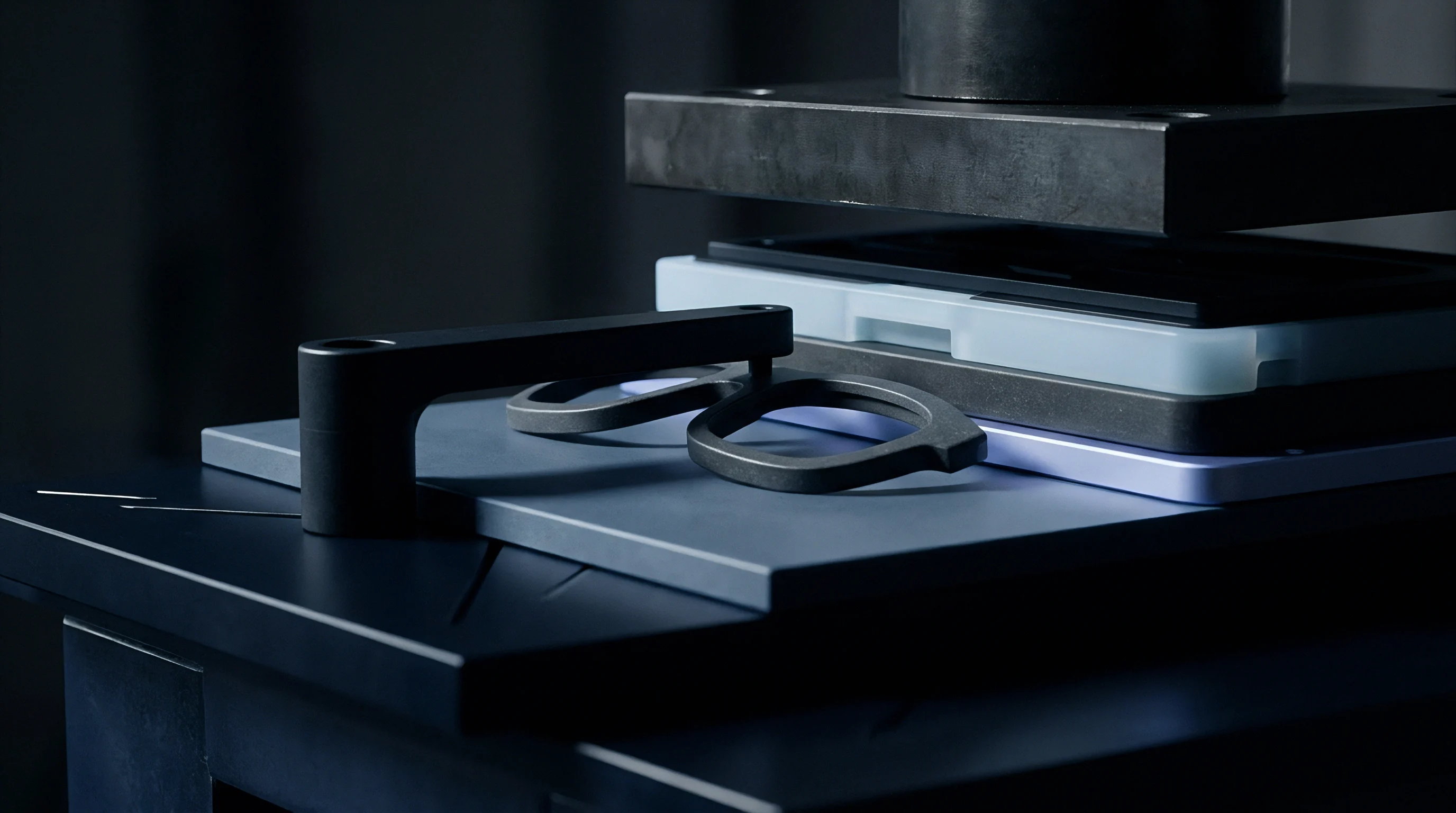
Conditioning ultra-low electric charges generated during micro injection cycles requires shielded high-impedance coaxial transmission paths. High impedance cables resist environmental noise. Electrical charge produced by piezoelectric transducers cannot travel through conventional copper wiring without immediate signal loss.
Special low-noise coaxial cables featuring conductive graphite coatings around Teflon dielectric layers shield small charge outputs from stray electromagnetic fields emitted by press heating bands, servo motors, and magnetic clamping plates.
High-Impedance Cabling and Amplifier Sensitivity
Piezoelectric transducers deliver low electrical output that degrades rapidly when exposed to environmental humidity or magnetic fields. Charge amplifiers convert picocoulomb signals into stable zero to ten Volt analog signals suitable for data acquisition hardware. In micro-moulding applications, sensor signal conditioning relies on ultra-sensitive range settings because small contact areas generate low force inputs.
| Pin Tip Diameter (mm) | Melt Contact Area (mm²) | Transferred Force at 1000 bar (N) | Nominal Charge Output (-4.0 pC/N) | Signal-to-Noise Ratio at 0.05 pC Drift |
|---|---|---|---|---|
| 0.4 | 0.126 | 12.6 | -50.3 pC | 1006:1 |
| 0.6 | 0.283 | 28.3 | -113.1 pC | 2262:1 |
| 0.8 | 0.503 | 50.3 | -201.1 pC | 4022:1 |
| 1.0 | 0.785 | 78.5 | -314.2 pC | 6284:1 |
| Calculations assume uniform pressure distribution across pin face, zero axial sleeve friction, and nominal transducer sensitivity of -4.0 pC per Newton. | ||||
Charge amplifier selection dictates signal clarity. Multi-channel amplifiers feature programmable measuring ranges, allowing operators to adjust scale factors from ten picocoulombs per Volt up to ten thousand picocoulombs per Volt. Setting amplifier range appropriately maximizes digital signal resolution without clipping peak pressure values during final packing phase shocks.

Drift Compensation and Pressure Integrals
Charge amplifiers converting picocoulombs to voltage achieve zero-point stability across thousands of consecutive moulding cycles through active baseline reset timing. Piezoelectric circuits exhibit inherent electrical drift over time due to amplifier operational drift and residual cable charge. Resetting the charge amplifier to zero volts while the mold stands open between injection cycles eliminates cumulative baseline offset errors.
In high-speed micro moulding running cycle times under two seconds, amplifier reset timing must execute within a twenty-millisecond window between part ejection and mold closing.
Calculating pressure integrals provides a reliable metric for evaluating micro-part density and volumetric fill. Processing software integrates the cavity pressure curve over time, yielding a pressure-time integral expressed in bar-seconds. Variations in raw material viscosity, melt temperature, or switchover timing alter curve shape and integral values, providing real-time quality feedback for micro-components whose weight variations remain undetectable on standard shop floor scales.
Whether charge amplifier drift during continuous sub-second micro moulding cycles can be completely eliminated through hardware filtering without damping true dynamic pressure peaks remains an open technical challenge.


Control
Automating machine behavior based on internal tool events transforms process stability in micro-scale moulding operations. Real-time monitoring cuts scrap rates. Conventional injection presses switch from speed-controlled filling to pressure-controlled holding based on screw stroke position or hydraulic system pressure.
In micro-moulding, small cushion volumes make position-based switchover unreliable. Small fluctuations in check-valve closure timing or thermal expansion of the injection screw cause fill variations that yield short shots or flash.

Switchover Determination for Small Shot Mass
Transitioning from velocity control to pressure hold using screw position produces significant weight variations when processing sub-gram mouldings. Viscosity variations shift cavity filling times. Cavity pressure switchover relies on real-time voltage signals from piezoelectric transducers to trigger press response.
As molten polymer fills the micro-cavity, pressure remains low until resin reaches the sensor face, triggering a steep pressure rise as melt meets cavity walls.
Programming the injection moulding machine controller to initiate pressure hold when cavity pressure reaches a pre-set threshold ensures identical volumetric cavity filling across every production cycle. Early switchover causes short shots. Real-time cavity pressure switchover compensates automatically for material viscosity shifts, regrind batch variations, and thermal changes in barrel temperature zones.
The checklist below outlines criteria for evaluating sensor signal integrity during process window setup:
- Peak Pressure Plateau Identification ensures cavity packing stability by verifying pressure curves exhibit smooth flat peaks rather than sharp erratic spikes.
- Filling Time Consistency verifies shot-to-shot melt front velocity by tracking time elapsed between injection start and initial pressure signal response.
- Decompression Baseline Verification confirms total release of residual mold force by inspecting signal returning to true zero before tool opening.
- Pressure Integral Area Stability calculates shot consistency by maintaining integral variation under two percent across fifty continuous machine strokes.
Automated Quality Sorting and Defect Gates
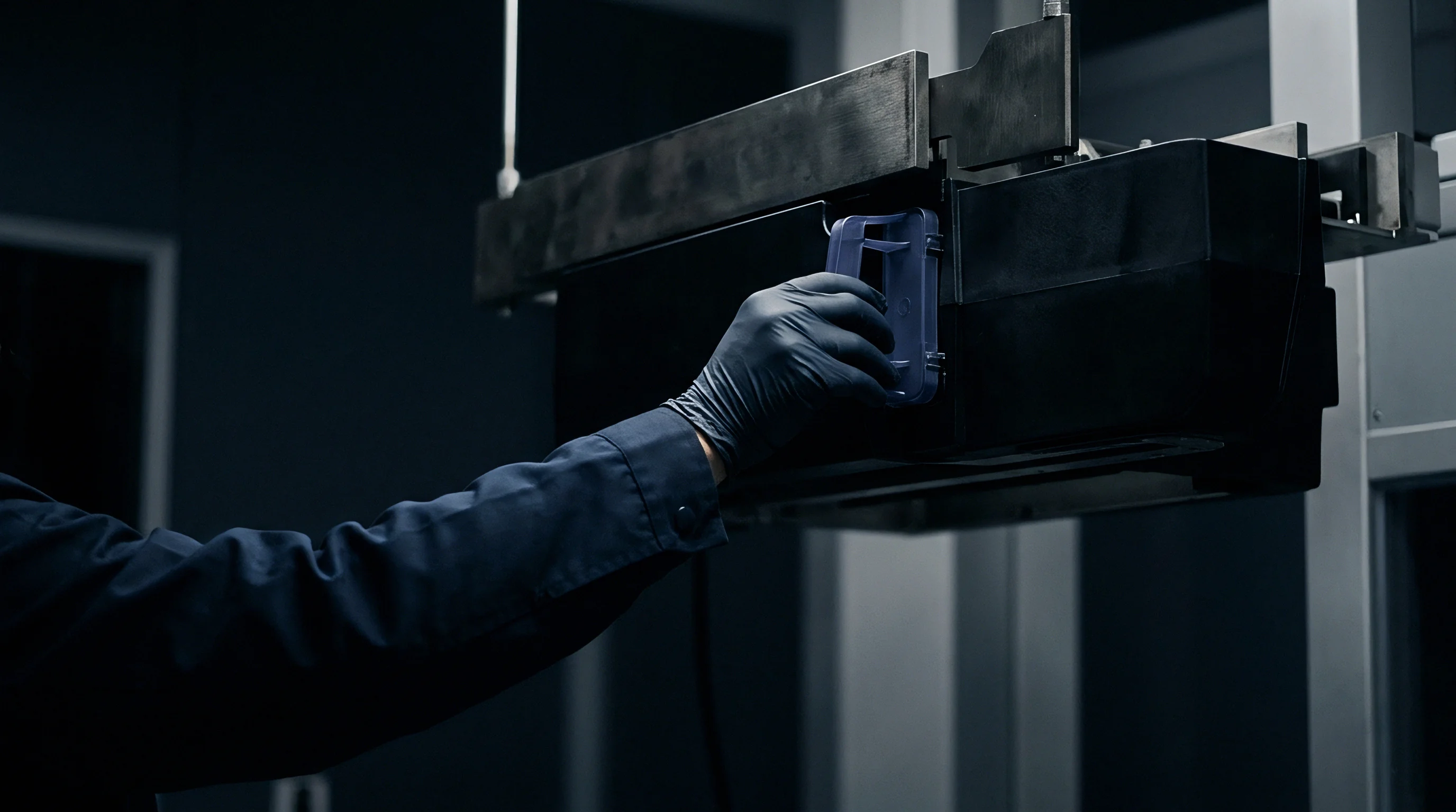
Evaluating peak pressure values and curve areas for every injection cycle enables immediate separation of out-of-spec parts. Automated robot interfaces or air-blast sorting gates receive digital pass or fail outputs directly from cavity pressure monitoring hardware. Parts demonstrating peak pressure values outside narrow control bands, such as plus or minus fifteen bar, are rejected before entering production collection bins.
Cavity pressure traces reveal internal part density variations long before dimensional changes become measurable under optical microscopes.
Decoupled moulding strategies utilize cavity pressure signals to segregate subtle quality variations in micro-medical parts. Sorting criteria monitor multiple envelope boundaries along the pressure curve, including fill rate slope, peak packing pressure, and cooling decay rate. Automated part segregation eliminates manual optical inspection costs while providing full quality trace documentation for regulated medical components.
Switching from injection velocity control to cavity pressure hold at the exact moment the melt reaches full cavity volume prevents flash while ensuring complete feature fill.


Budget
Financial commitment to cavity monitoring instrumentation alters tooling payback horizons and unit cost calculations. Installing piezoelectric pressure sensors, low-noise cables, charge amplifiers, and processing acquisition hardware adds significant initial cost to micro-injection tooling projects. Project engineers must calculate return on investment by weighing capital costs against scrap reduction, shorter cycle times, and automated quality verification savings.
Sensor Amortisation across Multi-Cavity Tooling
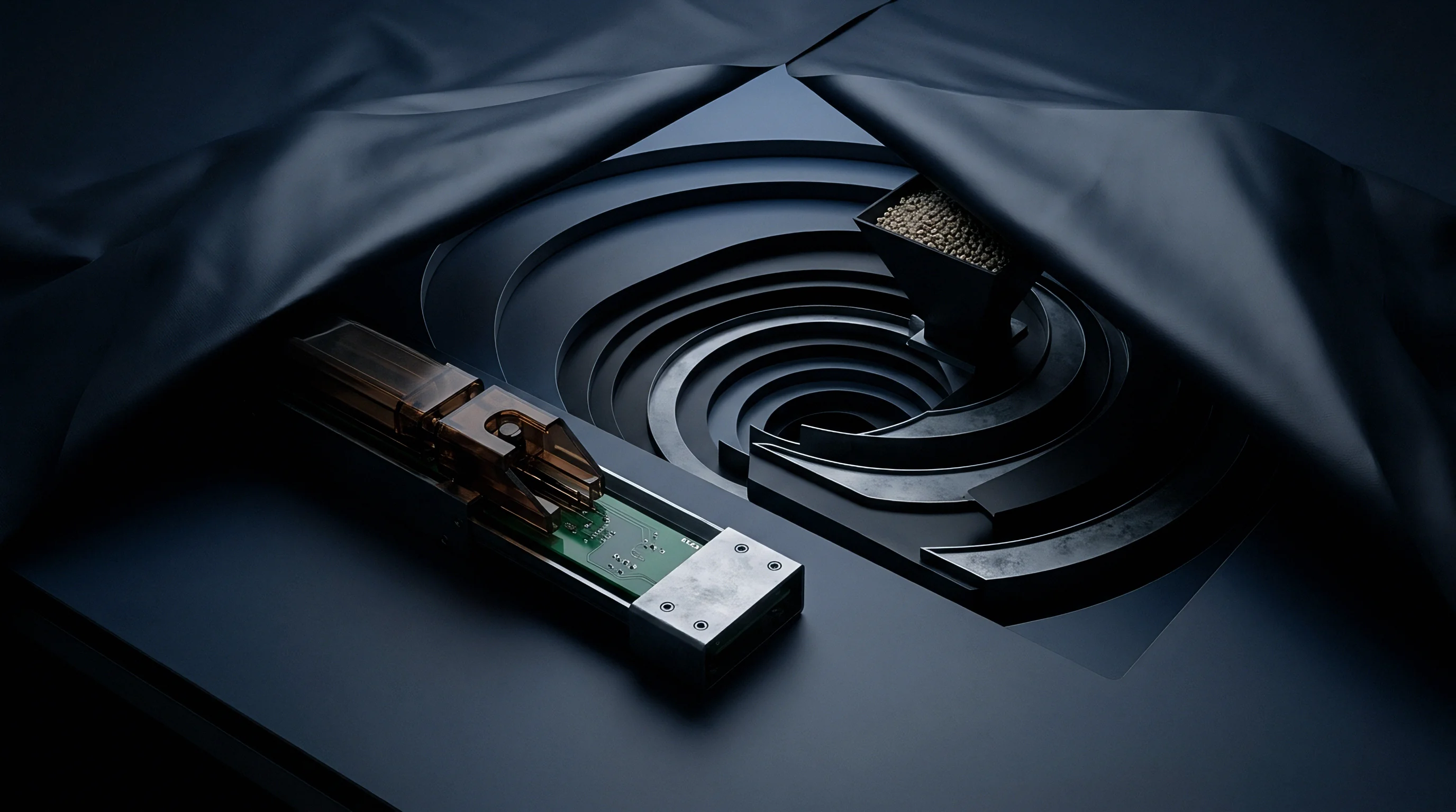
Cost modeling distributes hardware expenses across projected production volumes. High-cavitation micro-tools housing sixteen, thirty-two, or sixty-four cavities multiply sensor investment requirements. Equipping every cavity with dedicated pressure sensors becomes cost-prohibitive for non-medical components.
Engineers select strategic cavity monitoring layouts, placing sensors in critical cavities such as those furthest from the main sprue or adjacent to runner branch splits.
Sensors located in representative tool positions capture process variations across all cavities without incurring full multi-sensor tooling expenditures. A four-sensor array installed in a sixteen-cavity micro-tool monitors flow front balance, injection speed consistency, and pack density shifts across cavity quadrants. Scrap reduction amortizes sensor equipment expenses within thousands of operating hours on high-volume production lines.

Tool Maintenance and Replacement Provisions
Preventive maintenance schedules specify periodic transducer calibration every fifty thousand cycles. Piezoelectric sensors experience mechanical fatigue, thermal degradation, and cable wear over extended production runs. Tooling budgets must allocate funds for replacement measuring pins, spare sensor cables, and annual transducer recalibration services performed by certified metrology laboratories.
Protecting delicate sensor hardware during mold cleaning and routine maintenance extends operating lifespan. Toolmakers must remove transducers or install protective blanking plugs before submitting micro-cavity inserts to ultrasonic cleaning baths or chemical solvent immersion. Solvent residue residing inside sensor mounting bores carbonizes during re-heating, impairing mechanical preloads and causing permanent sensor signal insulation failures.
Integrating piezoelectric sensors into micro injection tooling establishes a permanent data record for every produced part, supporting medical device traceability and protecting molders against costly batch recalls.