Cavity Pressure Sensor Selection Criteria for Thermoplastic Tooling
Select direct quartz sensors for cosmetic-free dynamic packing control; use indirect pin transducers where surface markings are forbidden by drawing tolerances.

Signal
Thermoplastic injection moulds convert hydraulic push into hydraulic cavity resistance during the filling stage. Hydraulic pressure gauges mounted at the machine cylinder measure oil resistance rather than melt behavior inside the impression. Polymer viscosity shifts across resin lots, barrel thermal variations, and non-return valve leakage introduce discrepancies between barrel pressure and cavity pressure.
Direct measurement inside the cavity registers the exact physical state of the polymer melt during filling, compression, packing, and cooling phases. Processing engineers use this real-time trace to decouple machine behavior from part formation, isolating viscous flow resistance from mechanical drive losses.
Melt pressure spikes instantly. Translating melt force into an operational electrical reading depends on the transducer technology selected for the tool build. Piezoelectric quartz elements and piezoresistive silicon strain gauges dominate modern tool instrumentation, each exhibiting distinct signal characteristics, physical life spans, and integration envelopes.
Piezoelectric Quartz Transduction Mechanics
Piezo elements cut along the crystalline x-axis yield electrostatic charges directly proportional to applied compressive load. Quartz exhibits exceptional rigidity, with elastic modulus values around 78 gigapascals, preventing mechanical deflection from altering the cavity volume during pressurized stages. Quartz elements generate electrostatic charges.
The generated charge measures in negative picoCoulombs per bar of applied force. A direct sensor with a front diameter of four millimeters produces approximately minus nine picoCoulombs per bar. High-impedance cables transfer these minute electrical charges directly to an external charge amplifier, which converts picoCoulombs into a proportional zero-to-ten-volt analog signal or digital bus packet.
A rigid sensor diaphragm prevents cavity volume deflection under two thousand bar melt loads.
Operational stability depends on maintaining perfect electrical insulation across the entire high-impedance transmission path. Contamination on connector faces drops insulation resistance below ten terraohms, causing signal drift and false pressure readings during prolonged holding stages. Quartz sensors withstand continuous tool temperatures up to 200 degrees Celsius without active cooling, making them suitable for engineering thermoplastics including polyamides, polycarbonates, and polybutylene terephthalate.

Direct Contact against Pin Transmission
Front-face diaphragms sit exposed to molten resin, recording fluid pressure without intermediary mechanical linkages. Direct sensors eliminate pin friction. Flush installations prevent polymer freeze-off from masking packing decay, yielding precise pressure histories throughout the hold phase.
Direct placement leaves an imprint ring on the cosmetic face of the moulding, typically between 2.5 millimeters and 4.0 millimeters in diameter. Visible ejector witness lines already occupy non-cosmetic areas, whereas direct sensor diaphragms demand prime real estate on aesthetic walls, optical lenses, or hermetic sealing perimeters.
Indirect sensors sit behind existing ejector pins or dummy force-transmission pins located inside the ejector plate assembly. Mechanical transmission separates the active sensor body from the molten stream, shielding sensitive electronic components from abrasive glass fibers and corrosive off-gassing. Force transmission depends on the mechanical sliding fit of the ejector pin inside its tool steel guide bore.
Tight pin clearances below six microns prevent polymer flash from binding the shaft, yet tight tolerances increase friction under high lateral thermal expansion.
Mould builders evaluate sensor formats against geometric part constraints and maintenance budgets:
- Direct piezoelectric transducers expose a flat metallic diaphragm to the cavity volume, recording rapid pressure transients with high frequency response while creating a permanent circular witness mark on the finished component.
- Indirect pin transducers rest beneath hardened ejector shafts inside the ejector plate, preserving cavity surface cosmetics at the expense of frictional force attenuation along the pin guide channel.
- Piezoresistive strain sensors utilize Wheatstone bridge circuits bonded to deflecting diaphragms, generating low-impedance millivolt signals that tolerate lower insulation resistance on humid shop floors.
- Combined pressure and temperature sensors integrate an infrared pyrometer alongside a quartz crystal face, measuring simultaneous thermodynamic cooling rates and melt compressibility at a single cavity coordinate.
Mismatched sensor selection creates compounding errors during process setup, producing undetected short shots, flash along mating parting lines, and erratic gate seal transitions across production shifts.


Seat
Cavity pocket geometry dictates whether a transducer survives sustained clamp tonnage across production campaigns. Tool steel deflects under peak injection pressures, concentrating compressive stresses onto the sensor housing if pocket dimensions depart from manufacturer specifications. Toolmakers cut sensor pockets into hardened tool steels, typically 1.2343, 1.2344, or pre-hardened 1.2738, matching mounting bores precisely to the transducer body diameter.
Improper pocket depth leads to two distinct failure modes: recessed mounting creates a localized plastic flash boss that jams ejection, while proud mounting creates a high-pressure pinch point that brinells the sensor diaphragm under clamping loads.
Steel pockets demand strict concentricity. Machining allowances follow tight limits to avoid sensor preloading during installation. Direct sensors require flat-bottomed counterbores with perpendicularity held to 0.01 millimeters relative to the parting line surface.
Bore Tolerances and Concentricity Limits
Machinists grind transducer mounting wells to H7 dimensional allowances, keeping cylindrical runout within five microns. Misalignment between the sensor axis and the cavity normal axis induces asymmetric bending loads across the internal quartz disc. Asymmetric loading reduces sensor measurement accuracy by eight to twelve percent, causing artificial pressure spikes during injection acceleration.
Direct sensors eliminate pin friction. Tool deflection alters sensor preloads. Counterbore bottoms require a surface finish of Ra 0.4 microns to ensure even mechanical seating across the entire sensor rim.
Sensors set proud of cavity steel concentrate clamp tonnage onto quartz crystal faces.
Indirect installations demand identical alignment rigor for the force transfer pin. The pin length matches the distance from the sensor face to the cavity surface within a tolerance of minus zero point zero two millimeters to zero millimeters. Thermal expansion calculations govern pin fabrication.
Take an ejector pin of 100 millimeters length operating in tool steel at 80 degrees Celsius with a delta of 60 degrees Celsius above ambient: steel expansion equals approximately 0.07 millimeters. Ignoring this thermal growth causes the pin to stand proud of the cavity surface during steady-state production, generating cosmetic indentations and applying artificial mechanical preload onto the transducer base.
| Transducer Format | Front Diameter (mm) | Maximum Pressure (bar) | Temperature Limit (°C) | Rigidity Modulus (kN/µm) | Nominal Sensitivity |
|---|---|---|---|---|---|
| Miniature Direct Quartz | 2.5 | 2500 | 200 | 1.5 | -9.4 pC/bar |
| Standard Direct Quartz | 4.0 | 2000 | 200 | 3.0 | -4.8 pC/bar |
| Indirect Quartz Load Cell | 6.0 | 2000 (Calculated) | 120 | 8.0 | -4.1 pC/bar |
| Indirect Strain Gauge | 10.0 | 1500 (Calculated) | 80 | 0.8 | 2.0 mV/V |
Thermal Isolation in High Temperature Tooling
Processing polyether ether ketone at melt temperatures exceeding 380 degrees Celsius pushes core steel beyond standard thermal thresholds. High-heat resins demand tool oil temperatures of 160 to 200 degrees Celsius to achieve nominal crystallinity. Piezoelectric quartz maintains stability up to its Curie point of 573 degrees Celsius, but sensor housing seals, electrical cables, and signal connectors degrade rapidly above 200 degrees Celsius.
Thermal shock induces signal drift. Tool designers machine thermal insulation gaps between the cavity insert and the sensor pocket, or channel cooling fluid loops directly behind the sensor mounting plate.
Installation technicians follow an orderly sequence to secure reliable transducer seats without damaging quartz elements:
- Hole deburring and cleaning removes micro-burrs and EDM scale from the bore walls using specialized brass reamers.
- Depth micrometer verification confirms seat depth against tool drawings to prevent proud or recessed mounting conditions.
- Preload spacer fitting adjusts indirect pin stacks to zero mechanical float prior to bolting the sensor housing into position.
- Torque wrench tightening applies manufacturer-specified torque onto sensor retaining nuts to establish precise internal crystal tension.
Toolmakers defend oversized sensor pocket clearances on trial tools by claiming generous machining gaps permit thermal expansion and prevent binding during initial heat-up.


Placement
Sensor coordinates along the runner and cavity flow path determine what physical phenomena the data stream captures. Transducers placed near the gate reflect melt delivery conditions, packing pressure transmission, and gate freezing behavior. Transducers placed at the end of the flow path detect filling completion, gas venting efficiency, and mechanical hesitation.
Tool designers position sensors based on the specific defect mode targeted for automated process control. End of fill demands sensitivity. Thin cavities choke melt flow.
A single cavity sensor cannot control both switchover timing and pack-and-hold optimization simultaneously. Near-gate sensors capture immediate cavity filling, providing clean trigger thresholds for transitioning the injection press from velocity-controlled filling to pressure-controlled packing. End-of-cavity sensors monitor whether volumetric filling terminates completely, signaling short shots or flash conditions across changing resin viscosities.
What Dictates Transducer Location along Flow Paths?
Positioning near the gate registers packing pressure peaks and switchover timing directly from the injection unit. Placing a direct sensor within the first third of the flow path exposes the diaphragm to continuous high-pressure shear. Peak pressures near the gate routinely reach 800 to 1400 bar during pack stages.
Gate freeze-off manifests on the pressure trace as a distinct inflection point where pressure decay detaches from machine hydraulic holding pressure. Monitoring this knee allows setters to truncate unnecessary hold time, shaving two to four seconds off cycle times on thick-walled structural mouldings.
Placing sensors at the last point of fill captures the lowest cavity pressure values, typically between 150 and 350 bar. Transducers at this coordinate identify venting restrictions, cold slugs, and burn marks resulting from diesel effect compression. Detecting a pressure rise at the end of the flow path confirms complete volumetric cavity filling without overpacking the gate region.
Processing semi-crystalline polymers with high shrinkage requires balancing near-gate and end-of-fill readings to minimize internal stress differentials that cause post-mould warping.
A minimum end-of-cavity pressure threshold of two hundred bar prevents sink marks on distal ribs under five percent resin viscosity shifts.

Balancing Multi Cavity Family Geometries
Tools running asymmetric parts demand independent monitoring lines to catch localized filling starvation. Multi-cavity tools with identical impressions frequently display flow imbalance due to shear heating differentials in runner systems. Instrumentation layouts must account for balance verification.
For a 16-cavity connector tool running liquid crystal polymer, fitting sensors in every cavity adds substantial tooling capital, yet instrumenting only two cavities risks missing cavitation imbalances. Tool amortisation models dictate instrumenting four diagnostic cavities on a 16-cavity layout: two cavities closest to the sprue and two cavities at the geometric extremities of the runner distribution block.
Establishing process control across complex layouts relies on a systematic progression of physical verification steps:
- Cut short shots at ninety-five percent volumetric fill without pack pressure to establish the true physical end of fill.
- Inspect filling symmetry across all cavities to confirm runner balance before assigning sensor locations.
- Mount the primary control sensor inside the cavity that fills last under lowest machine injection velocity.
- Mount secondary monitoring sensors inside the cavity that fills first to detect overpacking and flash risks.
- Connect transducers to the data acquisition system and establish baseline integral pressure curves across thirty stable production cycles.
Locating a sensor directly opposite a restricted gate guarantees turbulence, scouring the sensor face with abrasive melt and destroying quartz diaphragm accuracy before the first production run concludes.


Drift
Prolonged dwell times under high packing pressure introduce measurement decay into analog voltage conversions. Charge amplifiers operate by holding electrostatic charges on reference capacitors. Real dielectric materials leak small quantities of charge over time, resulting in natural signal drift during extended cycles.
Standard injection moulding cycles running under sixty seconds experience negligible drift effects when insulation resistance exceeds specification. Industrial cycles exceeding three minutes, common in thick-section optical lenses or structural parts, encounter baseline drift that shifts zero-point calibration between shots.
Moisture destroys high impedance insulation. Quartz crystal sensors generate electrostatic charges measured in picoCoulombs. A microscopic fingerprint, cutting oil aerosol, or atmospheric condensation on a connector pin provides an electrical path across the high-impedance terminal, collapsing the electrical charge before the amplifier converts the signal.

How Dynamic Pyroelectric Offsets Distort Monitoring?
Rapid temperature swings during molten polymer contact excite secondary charge migrations across the crystal faces. Tourmaline and quartz elements exhibit pyroelectric behavior, generating electrical charges in response to rate of temperature change (dT/dt) alongside pure mechanical stress (dF/dt). When molten polypropylene at 230 degrees Celsius contacts a sensor face seated in tool steel at 40 degrees Celsius, the sudden thermal shock generates a false positive pressure spike lasting several milliseconds.
Pyroelectric offsets introduce three to seven percent signal distortion during the critical dynamic filling phase before thermal equilibrium stabilizes across the diaphragm.
Acoustic and sonar hydrophones aboard naval vessels encounter identical charge migration phenomena when transitioning thermoclines, requiring charge cancelation circuits to separate sound pressure from dynamic thermal gradients. Injection mould monitoring borrows these filtration methods, utilizing differential quartz crystal geometries or digital thermal compensation algorithms embedded in high-speed acquisition hardware to strip pyroelectric noise from dynamic melt pressure curves.
| Interface Variable | High-Impedance Analog | In-Sensor Digital Bus | Industrial Strain Gauge | |
|---|---|---|---|---|
| Signal Format | Charge (-pC) | RS-485 / CAN | Voltage (0-10 V / mV) | |
| Cable Sensitivity to Noise | High (Requires Shielding) | Negligible | Moderate | |
| Maximum Cable Length | 5 meters | 50 meters | 20 meters | |
| Minimum Insulation Resistance | 10^13 Ohms | 10^8 Ohms | 10^9 Ohms | |
| Thermal Drift Coefficient | 0.02% FS / °C | Compensated Internal | 0.05% FS / °C | |
| Methods note: Measured at 23 degrees Celsius ambient temperature using shielded Teflon low-noise coaxial cables under laboratory grounding conditions. | ||||
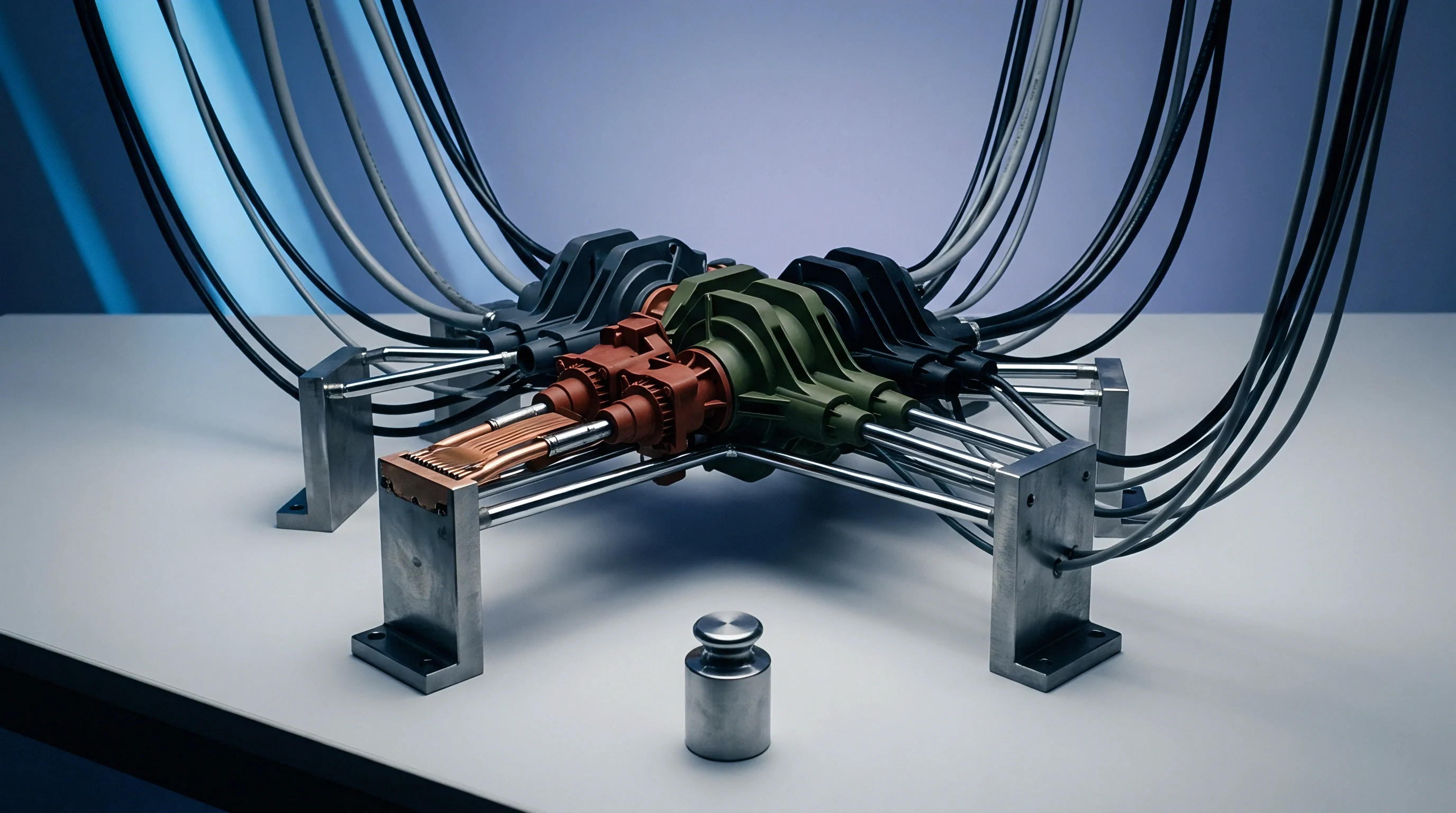
Cable Shielding and Charge Amplifier Impedance
Coaxial conduits linking the tool junction box to the cabinet require insulation resistance exceeding ten terraohms. Cable capacitance degrades weak signals. Standard factory environments expose signal lines to high electromagnetic interference generated by servo-electric drive motors, hydraulic proportional valve solenoids, and magnetic platen clamping systems.
Bending, pinching, or dynamic flexing of high-impedance coaxial cables generates triboelectric noise, where friction between cable insulation and braided shield creates parasitic electrostatic charges. Machine builders route sensor lines through dedicated steel conduit channels isolated from high-voltage heater bands.
The desk cannot fully defend the widely cited rule that cable lengths must never exceed five meters without intermediate line amplifiers. Tool layouts on four-thousand-tonne presses frequently require eight meters of run between moving core faces and external operator panels. Buyers facing this layout specify in-mould digital converters mounted directly to the tool base, transforming sensitive charge signals into noise-immune digital packets prior to crossing moving press hinges.
How far dynamic thermal shock distorts the true pressure integral during the first fifty milliseconds of filling in ultra-thin micro-mouldings remains an open question across the polymer processing industry.
Settlement
Commercial disputes regarding part non-conformance resolve rapidly when calibrated cavity data governs factory sign-off protocols. Tool purchase agreements frequently stipulate process capability indices (Cpk) exceeding 1.33 on critical drawing dimensions. Dimensions governed by thermal shrinkage correlate directly with the integral of cavity pressure over time, known as the pressure integral.
Relying on hydraulic machine parameters leaves buyers exposed to machine-to-machine variability when tooling transfers between supplier facilities. A mould qualified on an all-electric press in Japan behaves differently when mounted on a worn hydraulic press in Eastern Europe unless cavity pressure profiles match across both production floors.
First article inspections link dimensional compliance to cavity pressure envelopes. Frozen layers insulate downstream sensors. By monitoring cavity pressure curves across qualification runs, buyers identify whether dimensional variation originates from machine instability or raw material batch variance.

Acceptance Run Verification Metrics
Procurement teams inspect twenty-four-hour continuous production records, checking integral curves against part weight tolerances. A stable cavity pressure curve guarantees that every shot experienced identical volumetric packing, holding molecular orientation and volumetric shrinkage within tight bands. DIN 16742 tolerance grades for injection moulded plastics define achievable dimensional bounds based on material shrinkage classes.
Achieving tolerance grade TG4 on glass-filled polyamides demands peak cavity pressure repeatability within plus or minus fifteen bar across an entire production shift.
Uncalibrated pins yield erratic records. Hardened tool steels resist brinelling. Tooling contracts that omit cavity sensor specifications force buyers to accept parts evaluated solely on post-mould cooling checks, delaying defect recognition until parts reach assembly plants weeks later.
Automatic part sorting gates controlled by cavity pressure threshold signals divert short-shot parts directly into scrap bins, preventing unpressurized components from entering shipping packaging.
Under DIN 16742 tolerance grade TG4, part dimension compliance requires cavity pressure integral repeatability within three percent shot to shot.

Tooling Ownership and Process Data Transfer
Original equipment manufacturers retaining tool capital assets frequently encounter friction when extracting proprietary sensor profiles from contract moulders. Tooling supply contracts must explicitly stipulate sensor ownership, calibration responsibility, and signal output interfaces. Sensor life expectancies range from two million to ten million cycles under normal production conditions, but processing abrasive glass-filled or flame-retardant polymers erodes sensor faces prematurely.
Clear maintenance clauses allocate replacement costs for worn direct sensor diaphragms and damaged connection cables between the moulder and the asset owner.
Contractual clarity extends to the digital process data generated during production runs. OEM buyers specify full ownership of raw cavity pressure time-series logs, using cloud-linked data acquisition cabinets to audit supplier process stability in real time. Access to raw curve files prevents contract moulders from masking machine downtime, resin degradation, or unauthorized regrind additions by manipulating cycle counts.
Tool supply contract section 8.4 mandates that tool qualification sign-off requires three consecutive four-hour capability runs holding a cavity pressure peak variance under two percent, binding final tool milestone payments directly to sensor verification data.