Predictive Thermal Core Modeling for Conformal Cooling Circuit Optimization in Complex Thermoplastic Tooling
Predictive transient thermal modeling optimizes conformal core channels, balancing heat extraction and structural integrity to minimize cycle time and part warpage.

Flux

Transient Heat Transfer across Mold Steel Boundaries
Thermal core modeling determines cycle limits by calculating the local caloric extraction rate per square millimeter of cavity surface. In semi-crystalline engineering thermoplastics such as 30 percent glass-filled polybutylene terephthalate (PBT-GF30) and polyphenylene sulfide (PPS), heat extraction dictates solid layer growth, crystalline morphology, and residual stress states. A conventional straight-line drilled waterline leaves deep core geometry thermally isolated.
Steel temperatures climb across consecutive cycles, extending the necessary cooling time to reach ejection stiffness. Conformal cooling resolves this thermal bottleneck by matching cooling channel geometry directly to the contour of the plastic part.
Transient conduction governs this process during the solid fraction formation phase. The fundamental governing relationship balances transient heat storage against diffusive conduction and convection into the coolant fluid:
ρ_s · C_p,s · (∂T/∂t) = ∇ · (k_s ∇T)
Here, ρ_s represents steel density, C_p,s represents steel specific heat capacity, and k_s represents steel thermal conductivity. At the tool-polymer boundary, thermal contact resistance introduces a temperature discontinuity. Before polymer solidification, injection pressure drives close contact between the melt and the cavity surface, yielding heat transfer coefficients between 1500 and 2500 W/(m²·K).
As the thermoplastic transitions through its glass transition or crystallization point, volumetric shrinkage pulls the boundary layer away from the tool steel. The resulting microscopic air gap drops the local heat transfer coefficient down to 200 to 450 W/(m²·K). Predictive core models calculate this decay across the holding phase to avoid underestimating cycle duration.
A tool boundary pulling away by fifteen microns drops interfacial conductance to three hundred watts per square meter kelvin.
Ignoring this contact resistance variation skews predicted ejection times by up to 28 percent. Tool builders often compensate by running chillers at lower setpoints, which leads to mold sweating and surface blemishes. Accurate numerical simulation tracks the pressure-dependent heat transfer coefficient dynamically at every nodal step across the holding phase.

Convective Boundaries inside Conformal Passages
Cooling channels transfer thermal energy to the fluid phase through forced convection. The extraction performance depends directly on maintaining turbulent flow regimes across every circuit segment. Laminar conditions create an insulating boundary layer that throttles heat transfer.
Turbulent conditions scour the channel walls, ensuring steady thermal dissipation into the fluid bulk.
Engineers quantify this extraction using the Dittus-Boelter correlation for turbulent flow regimes inside circular and non-circular conformal channels:
Nu = 0.023 · Re^0.8 · Pr^0.4
The Nusselt number Nu determines the convective film coefficient h_c via the hydraulic diameter D_h and coolant thermal conductivity k_w:
h_c = (Nu · k_w) / D_h
A Reynolds number Re above 10,000 ensures stable convective performance across production shifts. Channel cross sections generated by laser powder bed fusion (LPBF) introduce surface roughness between 15 and 35 microns Ra. This roughness trips turbulence at lower Reynolds numbers than polished gun-drilled steel, but it increases Darcy friction factors and pressure loss per linear meter of passage. Designers adjust channel cross-sectional profiles and pump delivery heads to compensate.
Operating a chiller below 4 bar line pressure frequently starves deep core conformal channels when complex branching increases fluid resistance.


Gradient

Asymmetric Core Temperature Profiles and Part Warpage
Unequal cooling rates between opposing nominal walls induce asymmetric residual stress distributions across the molded profile. When core steel runs hotter than cavity steel, the core side remains molten longer. The core skin solidifies last, resulting in higher local shrinkage, thinner frozen boundary crusts, and inward warpage toward the hotter core face.
DIN 16742 sets strict dimensional acceptance bands for injection-molded technical parts, classifying allowable tolerance groups from TG1 down to TG9. Achieving TG3 or TG4 in high-temperature polymers requires core-to-cavity surface temperature variations below 4 degrees Celsius across the entire molding surface.
Deep core pins, shut-offs, and lifters present severe thermal dissipation challenges. Steel volume constraints limit traditional cooling options to slender bubblers or baffles, which produce stagnant fluid zones and thermal accumulation at core crests. Conformal circuits route internal coolant loops beneath parting surfaces, maintaining uniform steel mass coverage.
| Cooling Circuit Architecture | Core Steel Alloy | Peak Core Temp (C) | Bulk Temp Delta (C) | Cycle Seconds to 130C Ejection | DIN 16742 Class |
|---|---|---|---|---|---|
| Conventional Gun-Drilled Baffle | 1.2343 (H11) ESR | 124.6 | 28.4 | 21.8 | TG6 |
| High-Conductivity Copper Insert | CuCr1Zr Beryllium-Free | 108.2 | 14.1 | 16.4 | TG5 |
| Conformal Circular LPBF Channel | 1.2709 Maraging 300 | 96.5 | 3.8 | 12.2 | TG3 |
| Conformal Tear-Drop Dual Loop | 1.2709 Maraging 300 | 93.1 | 2.1 | 11.0 | TG3 |
The data demonstrates the thermal limitations of standard straight-line cooling drills. Baffle cooling circuits leave wide core temperature deltas of 28.4 degrees Celsius, extending cooling cycles to 21.8 seconds. This persistent thermal delta increases warpage vectors, dropping part accuracy to TG6 tolerances.
Beryllium-free copper inserts improve heat conduction, but their thermal mismatch with the surrounding tool steel introduces mechanical stress risks under production clamp tonnages. Conformal passages lower peak core temperatures while cutting cooling duration by nearly half.

Solidification Kinetics in Semi-Crystalline Resins
Cooling rates govern crystalline domain nucleation and growth rates in polyamides and polyesters. Slow core cooling produces large spherulitic structures, while fast quench cooling produces small spherulites and amorphous regions. Large spherulitic morphology increases stiffness and density, but it reduces ultimate impact strength and introduces local stress risers near sharp transition radii.
Uneven crystal growth induces differential shrinkage across the part. While transverse linear shrinkage for unfilled PA66 averages 1.5 percent, high localized crystallinity can drive shrinkage past 2.2 percent. Predictive thermal core modeling balances heat extraction vectors to produce uniform cooling rates through the solidification range.
Conformal paths hold local temperature variations under 3 degrees Celsius, creating homogeneous crystalline microstructures that suppress post-mold warping and dimensional drift across shifts.
Process setters frequently mask unmodeled core hot spots by extending holding pressure times, which packs excessive polymer mass into the sprue and causes part sticking on ejection pins.


Lattice

Additive Channel Geometries and Manufacturing Constraints
Additive manufacturing via LPBF enables cooling circuits that track complex non-planar core surfaces. Designing these passages requires balancing fluid dynamics with additive manufacturing constraints. Unsupported horizontal circular channels exceeding 8 millimeters in diameter sag during powder bed melting, creating internal slag, dross, and cross-sectional distortion.
Tear-drop, elliptical, and self-supporting diamond cross sections eliminate the need for internal support structures while withstanding additive recoater blade forces. A self-supporting tear-drop profile with an apex angle of 45 to 60 degrees prevents internal collapse during powder melting. This geometric control produces clean internal channel walls, mitigating fluid boundary separation and localized pressure drops across complex circuit bends.
- Tear-Drop Cross Sections prevent powder sagging across horizontal spans while preserving optimal hydraulic diameters up to 12 millimeters without internal supports.
- Channel Distance Ratio maintains a center-to-surface spacing between 1.5 and 2.0 times the channel diameter to prevent thermal shadowing and cyclic fatigue failures.
- Filleted Junction Nodes smooth directional transitions using minimum radii of 3.0 millimeters, eliminating stagnant dead zones and fluid recirculations.
- Depowdering Escape Ports permit complete removal of unfused tool steel powder particles before vacuum furnace heat treatment and aging cycles.
Channel clearance under one and a half diameters risks steel cleavage under forty tons of cyclic injection pressure.

Sub-Surface Core Topography and Fluid Boundaries
Maintaining a uniform distance between the cooling channel and the molded part surface ensures consistent heat absorption across contoured tool faces. Deviations in this wall thickness cause localized hot or cold zones in the tool steel. A channel positioned too close to the cavity face generates extreme cyclic thermal gradients, risking thermal fatigue cracking on textured surfaces.
Conversely, a channel positioned too deep loses cooling efficiency, resulting in sluggish heat extraction akin to conventional gun drilling.
Finite element thermal core solvers optimize channel centerlines using transient sensitivity fields. The optimization algorithm analyzes the part geometry, identifying thick ribs, heavy bosses, and core projections where volumetric heat density peaks. The solver adjusts local passage depths and spacing to balance heat extraction against cyclic mechanical stress loads.
The toolmaker inspects internal conformal passages using industrial computed tomography before final machining to verify that channel paths are clear of trapped powder and internal voids.

Fatigue

Mechanical Stress Fields under Cyclic Tonnage
Tooling cores experience intense cyclic stresses during standard injection molding cycles. When the clamp closes, the machine applies clamping forces ranging from 1,000 to over 10,000 kilonewtons across the parting line. Injection pressures subsequently ramp from 800 to 2200 bar, transmitting intense hydrostatic forces into deep core projections.
These mechanical loads superimpose over internal fluid line pressures and thermal expansion stresses generated by the cooling channels.
The total stress state within an additively manufactured core follows the von Mises yield criterion, balancing multi-axial mechanical and thermal stress tensors:
σ_vm = sqrt( 0.5 · )
In high-cavitation production tooling, these stress reversals occur hundreds of thousands of times each month. Additive manufacturing defects, such as internal pores, un-melted powder inclusions, or micro-cracks, act as stress concentrators within the steel core. If local peak stresses exceed the endurance limit of the tool steel, micro-cracks propagate toward the cavity surface.
This leads to coolant leaks, catastrophic core fracture, and severe damage to adjacent tool steel inserts.

Why Do Printed Core Channels Crack under Shift Pressures?
Internal notch sensitivity within unpolished additive cooling channels triggers early core failures. As-printed LPBF internal channels exhibit surface roughness values up to 35 microns Ra. These rough surfaces feature microscopic valleys that concentrate cyclic stresses, accelerating fatigue crack growth under pressure reversals. Thermal core stress models incorporate this surface roughness as an empirical notch factor, calculating modified endurance limits according to the Marin equation:
S_e = k_a · k_b · k_c · k_d · k_e · S_e’
Here, the surface condition modification factor k_a drops from 0.90 for ground tool steel down to 0.45 to 0.60 for as-printed internal surfaces. Chemical polishing, abrasive flow machining (AFM), or chemical etching smooths these internal passages. Polishing lowers internal channel roughness to below 3 microns Ra, which restores the fatigue endurance limit and protects the core from early mechanical failure.
| Material Designation | Processing Condition | Yield Strength (MPa) | Thermal Conductivity (W/m·K) | Endurance Limit S_e (Cycles) | Notch Sensitivity Index (q) |
|---|---|---|---|---|---|
| 1.2709 Maraging 300 | LPBF Hardened 52 HRC | 1950 | 21.0 | 580 MPa (10^7) | 0.68 |
| 1.2709 Maraging 300 | As-Printed Unpolished Channel | 1100 | 15.5 | 260 MPa (10^6) | 0.82 |
| 1.2343 ESR (H11) | Forged Quenched Tempered 50 HRC | 1600 | 29.5 | 720 MPa (10^7) | 0.45 |
| Direct Metal Tooling 420 SS | LPBF Heat Treated 48 HRC | 1450 | 16.0 | 420 MPa (10^7) | 0.74 |
Post-build heat treatment dictates the mechanical reliability of additively manufactured cores. As-printed maraging steel exhibits low yield strength alongside residual tensile stresses from laser melting passes. Subjecting the printed cores to vacuum solution annealing followed by precipitation hardening at 490 degrees Celsius precipitates fine intermetallic nickel-cobalt-molybdenum compounds.
This heat treatment relieves residual printing stresses and raises core hardness to 52 HRC, providing the wear resistance and fatigue strength required for high-volume injection molding.
Omitting post-print vacuum stress relief allows residual thermal stresses to combine with cyclic injection packing pressures, triggering brittle core failures within early production runs.

Balance

Coupled CFD and Transient Conjugate Heat Transfer
Accurate core thermal modeling relies on coupled Conjugate Heat Transfer (CHT) numerical simulations. Simulating mold heat flow with constant boundary coefficients creates discrepancies between virtual cycle predictions and actual shop floor cycle times. CHT simulations solve transient Navier-Stokes fluid flow and solid steel conduction within a single computational model, capturing dynamic boundary interactions as plastic parts solidify.
Coolant circuits absorb heat along their length, warming the fluid as it traverses the core passage. As water absorbs heat, its temperature climbs, which decreases the core-to-coolant thermal gradient toward the end of the circuit. A balanced conformal design accounts for this temperature rise by sizing downstream channel diameters to maintain elevated Reynolds numbers and stable convective heat transfer coefficients.
- Domain Meshing Strategy builds boundary layer prism cells along channel walls using dimensionless wall distance values under 1.0, resolving viscous sublayers for accurate pressure drop calculations.
- Polymer Boundary Mapping applies dynamic cavity pressure and thermal contact resistance curves across the packing and cooling phases.
- Fluid-Solid Interface Coupling transfers local heat fluxes at every computational iteration, recalculating temperature-dependent fluid viscosity and Reynolds numbers throughout the cycle.
- Cooling Channel Convergence runs cyclic iteration passes until core steel temperatures match within 0.2 degrees Celsius between consecutive injection cycles.
A six-bar pressure drop across one internal circuit starves parallel branches of the volume needed to sustain turbulent flow.
CFD modeling identifies internal fluid recirculation zones, flow separation points, and stagnant eddies within complex core channels. Sharp internal elbows disrupt turbulent flow, reducing local Nusselt numbers and causing heat accumulation in nearby steel. Incorporating fluid vanes, smooth transitional fillets, and optimized branching geometries prevents flow stalling, ensuring consistent convective heat extraction throughout the core.

Circuit Routing under Flow Rate Realities
Cooling manifold flow distribution governs thermal uniformity across high-cavitation production molds. Tool designs that direct coolant through multiple complex conformal cavities in series accumulate excessive heat, running downstream cavities significantly hotter than upstream positions. Parallel circuit routing delivers fresh, cold water to each cavity, which maintains identical core thermal profiles across the entire mold plate.
Parallel layouts require careful fluid balancing to prevent uneven distribution. Coolant naturally flows along the path of lowest mechanical resistance. If one conformal channel exhibits higher pressure drops due to tighter radii or longer loops, coolant bypasses that circuit, starving the core and causing unexpected hot spots.
Numerical modeling adjusts local passage diameters across parallel paths, balancing circuit pressure drops to guarantee uniform volumetric flow to every mold cavity.
A production tool running twelve cavities with unbalanced parallel lines produces erratic, cavity-dependent dimensional variations that evade standard statistical process controls.

Yield

The Direct Math of Mold Cycle Optimization
Cycle time dictates the economics of high-volume technical injection molding. Machine amortisation, labor overhead, and chiller energy consumption accrue per cycle second across each mold cavity. Thermal extraction during cooling constitutes 60 to 75 percent of the total injection cycle for engineering polymers.
Optimizing core heat extraction through conformal cooling cuts cycle times, increasing part output without the capital investment of additional molding presses.
Consider an eight-cavity injection mold producing a glass-reinforced polybutylene terephthalate (PBT-GF30) electrical connector housing with a 3.2-millimeter thick central core shut-off. Conventional cooling drills achieve a stable production cycle of 22.0 seconds, yielding an hourly output of 1,309 parts. Integrating predictive thermal modeling to design LPBF conformal maraging steel cores drops the required cooling duration from 14.5 seconds down to 6.5 seconds.
This reduction yields a finished cycle time of 14.0 seconds, raising output to 2,057 parts per hour.
The financial impact of this cycle reduction reflects directly in the part production economics:
- Machine Hour Amortisation charges an engineering rate of 85.00 USD per operating hour on a fully integrated 250-ton electric molding press.
- Standard Processing Baseline requires 764 press hours to produce a volume of 1,000,000 parts at a 22.0-second cycle time, totaling 64,940 USD in machine processing costs.
- Conformal Production Setup requires 486 press hours to produce the same 1,000,000 parts at a 14.0-second cycle time, totaling 41,310 USD in machine processing costs.
- Production Savings Margin yields direct operational savings of 23,630 USD per million units, excluding raw resin material costs.
- Additive Tooling Upcharge adds an initial manufacturing cost of 12,800 USD to build eight finished maraging steel conformal core inserts.
The conformal tooling investment breaks even after 542,000 production cycles. For manufacturing programs running multiple millions of parts over several years, cycle savings reduce production expenses, lower unit prices, and free up press capacity for additional work.

Toolroom Rework and Yield at Tool Sign-Off
Mismatches between virtual thermal models and physical tooling reveal themselves during early mold trials (T1). When unmodeled thermal hot spots cause part warping or sink marks on functional surfaces, the mold builder must modify the hardened steel tool. Adjusting hardened tool steel cores requires wire electrical discharge machining (EDM), welding, or manufacturing replacement core inserts, adding unexpected costs and production delays.
Predictive thermal modeling minimizes these costly design changes before steel is cut. Simulating transient conjugate heat transfer, phase transitions, and residual stress formations allows tooling engineers to optimize cooling channels and parting surfaces early in the design phase. Tool validation proceeds smoothly from T0 samples to final qualification, avoiding the expense of mold re-machining, scrap cycles, and missed project launch deadlines.
Suppliers often defend conventional core cooling by highlighting the lower initial tooling costs of straight-line drilling, leaving the buyer to absorb the long-term expense of extended cycle times and part yield fallout.


Audit
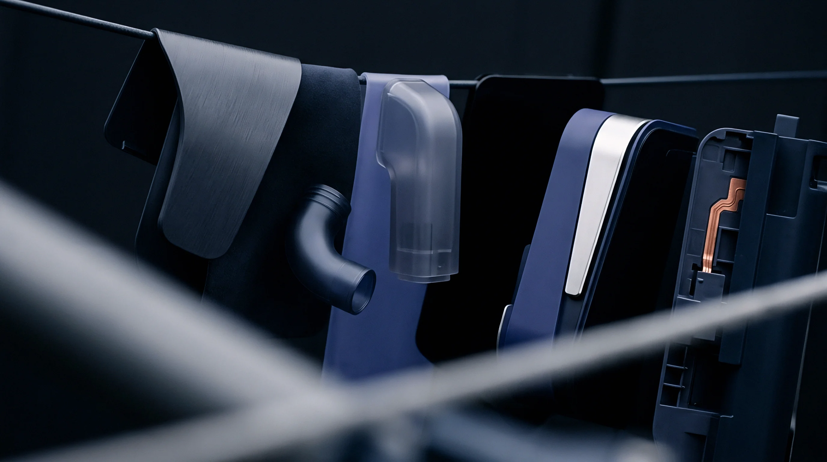
Checking Model Inputs before Steel Is Cut
Procuring conformal tooling inserts requires rigorous verification of engineering assumptions before manufacturing commences. Additive manufacturing with maraging steel or tool steels represents an irreversible capital investment. Once an insert is printed, vacuum heat treated, and wire cut, modifying internal conformal channels is impossible.
Tool buyers review the mold builder’s thermal simulation reports to verify that realistic boundary conditions were applied.
Engineering audits assess specific simulation inputs, rejecting models that rely on generic default parameters:
- Demand proof of dynamic, pressure-dependent heat transfer coefficients (HTCs) rather than static, unvarying boundary values at tool-polymer interfaces.
- Verify that the coolant fluid properties match the actual shop floor water-glycol mixtures and operating temperatures, accounting for glycol-induced drops in Reynolds numbers.
- Confirm that internal channel wall roughness values between 20 and 35 microns Ra are modeled in the flow resistance and pressure drop calculations.
- Inspect the solver convergence plots to ensure that cyclic thermal stability was maintained through at least ten simulated injection cycles.
A simulation showing uniform tool steel temperatures derived from a static, idealized heat transfer coefficient fails to predict real-world tool performance.
Acceptance Testing of Additive Inserts
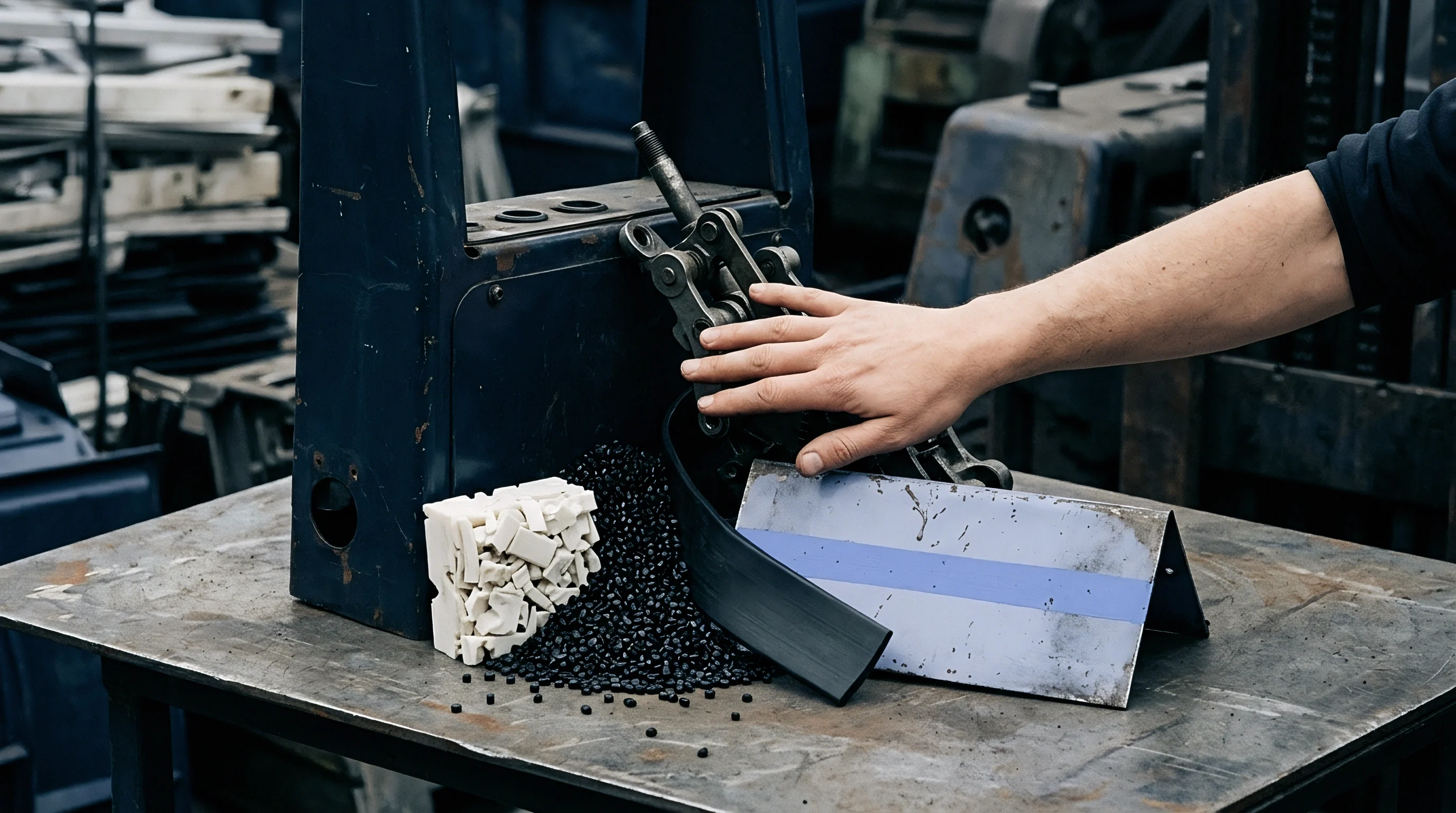
Verifying conformal core inserts requires multi-stage inspection before tool assembly. The toolmaker must confirm internal channel geometry, identify manufacturing defects, and evaluate mechanical integrity through physical testing. Non-destructive evaluation confirms that the internal cooling paths are clear of un-melted powder, porosity, and internal micro-cracks before the mold base is assembled.
The manufacturing inspection process tracks critical quality control milestones:
- Computed Tomography Scanning inspects internal channels to verify that wall thicknesses, diameters, and geometries match engineering CAD models.
- Hydrostatic Pressure Proof Testing pressurizes the isolated cooling passages to 15 bar for thirty minutes to confirm hermetic sealing and structural integrity.
- Flow Rate Benchmark Testing measures volumetric flow and pressure loss across each circuit, comparing results against simulation predictions to identify fluid restrictions.
- Ultrasonic Hardness Testing measures core surface hardness, verifying that vacuum heat treatment achieved 50 to 54 HRC across critical tool wear areas.
Documenting these quality milestones within the mold qualification package prevents early production disputes. When an additively manufactured core performs to specification during tool trials, the molder secures a stable, repeatable process window. The production cell runs continuously across unattended shifts, delivering high-precision technical parts within specification at optimal cycle times.
International tooling contracts typically mandate that tooling inserts failing flow rate verification tests by more than ten percent relative to simulation models undergo mandatory replacement at the toolmaker expense.