Amorphous Thermoplastic Rheology and Extruded Sheet Stretch Dynamics
Amorphous sheet stretch dynamics depend on strain hardening and thermal saturation to prevent localized necking and corner blowout during deep thermoforming.

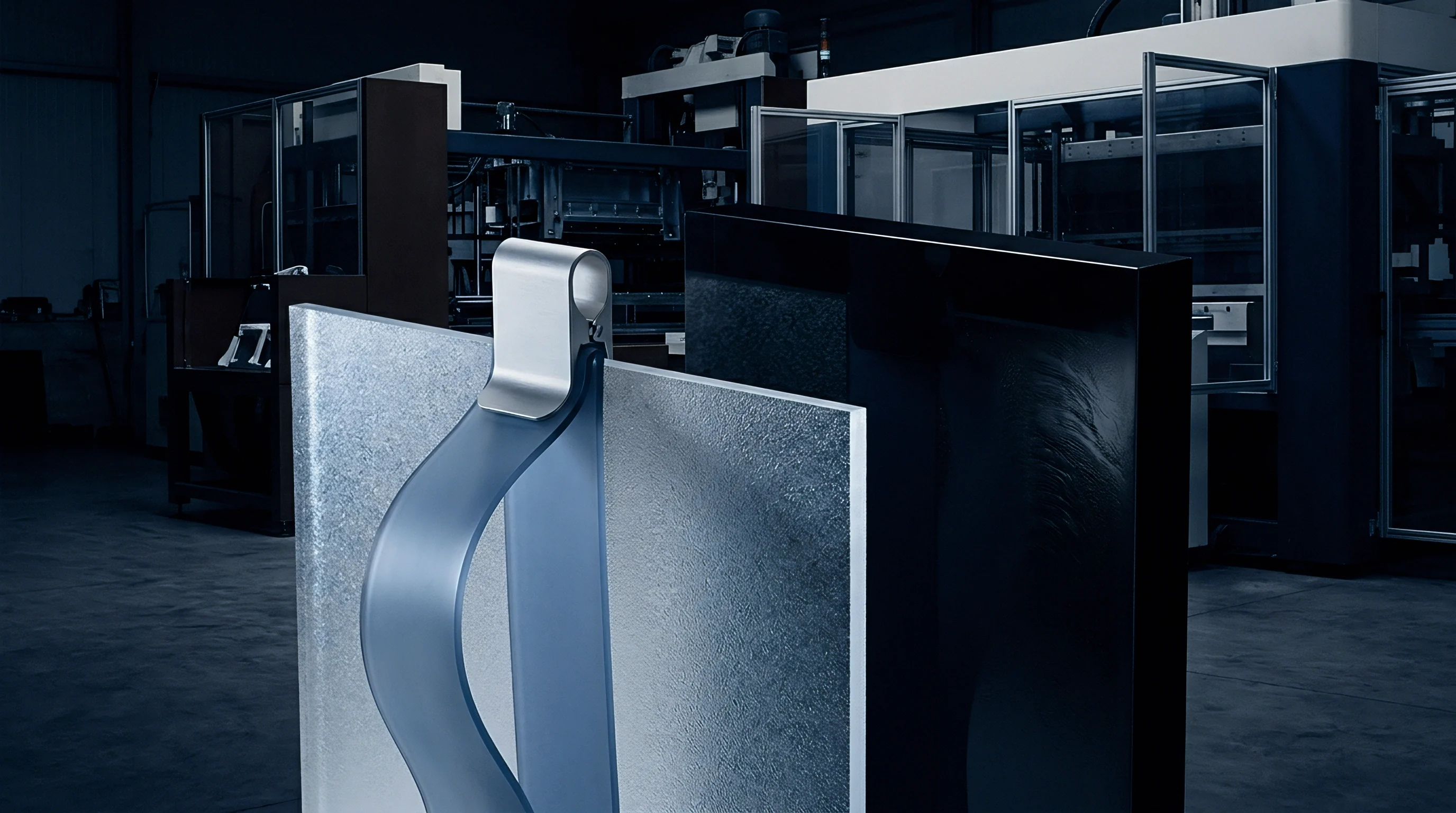
Melt
Exit behavior at the extrusion die sets baseline boundary conditions for downstream sheet deformation. As an amorphous melt clears the lips of a flat sheet die, channel wall shear constraints drop away. Molecular chains relax, driving cross-sectional die swell across the thickness profile while linear speed slows down.
Amorphous resins ~ polycarbonate, polymethyl methacrylate, high-impact polystyrene, and acrylonitrile butadiene styrene ~ retain significant viscoelastic memory through this exit zone. Melt elasticity dictates how well the web handles draw tension. If melt strength falls short, the unsupported sheet thins unevenly or tears between the die lips and the primary chill roll.
If elasticity runs too high, stress relaxation outlasts transit time to the take-off rolls, embedding heavy residual orientation in the sheet before thermoforming begins.
Moving from confined shear inside the die land to unconfined extensional flow across the draw gap reconfigures the stress state of the polymer network. Near the die walls, shear rates routinely hit 200 reciprocal seconds to 1000 reciprocal seconds, orienting chains along the main flow axis. Once the melt leaves the die land, elastic energy stored in the tangled chain network uncoils immediately.
The extrusate swells, increasing in gauge by 15 percent to 40 percent depending on the die land length-to-gap ratio, melt temperature, and resin molecular weight distribution. Controlling this swell comes down to managing zero-shear viscosity alongside the polymer’s relaxation time spectrum.
Viscosity modeling for amorphous sheet extrusion relies on modified Cross or Carreau-Yasuda parameters to capture the drop from the zero-shear plateau into power-law shear thinning. Under the low shear rates of free sheet drawdown, zero-shear viscosity governs resistance to sag and gravity-driven flow. Inside the die, higher shear rates push the melt into non-Newtonian behavior, lowering pumping pressure demands.
The Carreau-Yasuda model fits this response curve using five parameters: zero-shear viscosity, infinite-shear viscosity, relaxation time constant, power-law index, and a transition parameter governing the width of the shear-thinning zone.
| Polymer Chemistry | Zero-Shear Viscosity (Pa·s) | Relaxation Time (s) | Die Swell Ratio | Max Extensional Draw Ratio | Thermal Processing Window (°C) |
|---|---|---|---|---|---|
| Polycarbonate (PC) | 12500 | 0.08 | 1.12 | 2.4 | 275 to 310 |
| Polymethyl Methacrylate (PMMA) | 28000 | 0.45 | 1.28 | 1.8 | 220 to 255 |
| High-Impact Polystyrene (HIPS) | 8400 | 0.32 | 1.35 | 3.1 | 195 to 230 |
| Acrylonitrile Butadiene Styrene (ABS) | 16500 | 0.62 | 1.22 | 2.8 | 210 to 245 |
| Polyethylene Terephthalate Glycol (PETG) | 9800 | 0.14 | 1.18 | 2.6 | 200 to 235 |
The Trouton ratio ~ extensional viscosity divided by shear viscosity ~ serves as a practical benchmark for melt stability during sheet pull-down. While this ratio holds at three for simple Newtonian fluids, long-chain branched or highly entangled amorphous melts show sharp increases in planar and uniaxial extensional viscosities as strain rates climb. This extensional strain hardening counteracts localized necking.
If a thin spot begins to develop in the molten web, the local strain rate spikes, driving up extensional viscosity at that point and forcing adjacent, thicker material to yield instead. This self-healing mechanism preserves uniform gauge across web widths exceeding two meters.
Evaluating melt temperature variations isolates draw resonance phenomena in broad sheet lines. Draw resonance presents as a periodic, self-sustained surge in sheet thickness and web width, occurring when the draw ratio between die lip velocity and primary chill roll velocity exceeds a critical threshold. For linear amorphous polymers lacking significant strain-hardening characteristics, draw resonance begins at draw ratios as low as five to one.
The melt web experiences alternating thin and thick sections along the machine direction, accompanied by lateral edge re-entry. Increasing melt temperature worsens this instability by accelerating molecular relaxation rates, which lowers the transient extensional viscosity necessary to stabilize the free melt curtain.
A high relaxation time constant combined with elevated roll nip pressure locks planar anisotropy into amorphous sheet extrusates before thermal quenching occurs.
Extrusate stability tracks closely with the temperature-dependent relaxation spectrum. The Williams-Landel-Ferry equation models this behavior above the glass transition temperature, illustrating how relaxation windows shrink at higher temperatures. In polymethyl methacrylate processed at 230 degrees Celsius, a relaxation time constant of 0.45 seconds means molecular chains uncoil and align quickly under draw loads.
If the span between the die face and the roll nip yields a residence time under three times this relaxation constant, frozen orientation locks into the solid sheet. That residual stress triggers severe, uneven shrinkage during secondary thermoforming reheat cycles.
Thermal degradation during long residence runs alters melt viscoelasticity directly. If feed moisture exceeds 0.02 percent by weight, polycarbonate degrades predominantly via hydrolytic scission, causing zero-shear viscosity and melt strength to collapse immediately. Polymethyl methacrylate depolymerizes thermally at elevated temperatures, generating volatile monomers that leave micro-voids in the melt stream and cut extensional viscosity.
In acrylonitrile butadiene styrene, excess heat cross-links the polybutadiene rubber phase, driving up low-shear elasticity while compromising high-shear processability. These structural changes shift the melt flow index and degrade the extensional strain hardening exponent needed for uniform vacuum drawing downstream.
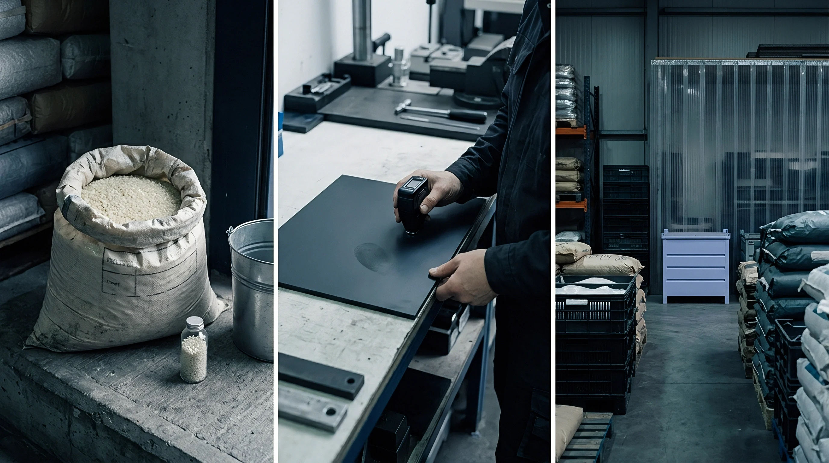
Viscoelastic Relaxation Spectra and Extrusate Swell Control
Quantifying relaxation spectra requires dynamic mechanical shear testing across a broad frequency sweep, since single-frequency tests miss the multi-scale dynamics of broad molecular weight distributions. Long chains dominate the elastic response at low frequencies, dictating extrusate swell at the die lips, whereas short chain segments govern shear thinning within the die land at high frequencies. Tuning die geometry to resin rheology depends on the Deborah number, comparing fluid relaxation time directly against the characteristic process time scale at the die exit.
When the Deborah number climbs above unity, elastic forces outweigh viscous dissipation, amplifying die swell and memory effects. A long die land with a length-to-gap ratio over twenty to one gives deformed entanglements sufficient residence time to reach equilibrium before exit. This relaxation eases stress peaks at the die lips, generating a flatter extrusate profile that tracks predictably through the chill roll nip.
Short die lands discharge high residual stresses abruptly, causing irregular transverse expansion and thick edges that interfere with uniform roll contact.
- Extrusate Swell Distortion manifests when molecular stress relaxation times exceed die exit residence times, causing unpredictable transverse expansion and gauge instability across the primary chill roll.
- Draw Resonance Fluctuation occurs when the take-off speed ratio exceeds the critical extensional stability limit of the melt, creating periodic machine-direction thickness waves.
- Melt Fracture Instability appears at high die wall shear stresses exceeding 0.14 Megapascals, creating surface sharkskin or cyclic stick-slip defects on the sheet exterior.
- Thermal History Degradation shifts the molecular weight distribution down, destroying zero-shear viscosity and causing catastrophic sheet sag during downstream heating cycles.
Die temperature zoning gives operators a direct tool for trimming cross-web swell variations. Raising heat at the die shoulders reduces local melt viscosity and accelerates chain relaxation, offsetting edge cooling caused by ambient heat losses. Flexible die lips adjusted via internal push-pull thermal bolts can alter the physical opening dynamically based on feedback from inline non-contact gamma-ray or beta-ray gauges.
Adjusting the local gap by ten micrometers shifts local shear rates, modifying extrusate swell and drawdown behavior to hold total sheet thickness within plus or minus 1.5 percent.
Melt elasticity governs sheet draw strength. The interaction between die lip land length, melt temperature, and chill roll take-off speed establishes the initial stress state of the solid polymer. If chill roll speeds exceed the natural melt exit velocity by more than 20 percent without sufficient melt strength, the extensional strain rate induces localized necking along the sheet margins.
This necking reduces the usable width of the extrusate, increasing edge trim scrap ratios and distorting the transverse optical properties of transparent amorphous grades.
Land length-to-gap ratios must be sized around the specific relaxation behavior of the resin. On polycarbonate lines, a land length ratio of twenty-five to one provides the thermal and mechanical buffering needed to damp out pressure pulses from upstream melt pumps. Pump output pulsation should stay under 0.5 Megapascal peak-to-peak to prevent visible gauge bands.
If gear pump speeds drift, dynamic pressure swings travel straight through the die channel, disrupting exit velocity across the lip and locking heavy cross-web bands into the finished roll.

Strain Hardening Dynamics in Planar Extensional Flow
Planar extensional flow occurs when a sheet is pulled in the machine direction under fixed width constraints, or when it expands uniformly in two directions during forming. How well a melt resists localized thinning depends on its transient extensional viscosity under steady strain rates. Linear amorphous polymers generally track three times the linear viscoelastic envelope up to large strains.
In contrast, modified grades formulated with high-molecular-weight tails or light branching show a distinct upward turn in transient extensional viscosity once past a critical strain threshold ~ the classic marker of strain hardening.
Strain hardening acts as a self-regulating mechanism during high-speed sheet drawdown and vacuum thermoforming. As a specific segment of the hot sheet thins, local strain increases rapidly. If the material exhibits strain hardening, its resistance to further deformation increases proportionately with the local strain, shifting the deformation zone to adjacent, less-strained material.
Without strain hardening, localized deformation accelerates rapidly into a necking failure mode, causing catastrophic sheet rupture during aggressive plug-assist drawing routines.
Extensional fixture attachments on rotational rheometers map stress-strain behavior across strain rates from 0.1 to 10 reciprocal seconds. For high-impact polystyrene processed at 180 degrees Celsius, an extensional strain rate of 1.0 reciprocal second demands a critical stress threshold to initiate uniform thinning. If processing temperatures rise to 210 degrees Celsius, thermal agitation disengages physical entanglements, suppressing the strain hardening response and lowering the maximum achievable draw ratio before localized rupture occurs.
Planar extensional strain hardening prevents localized necking in thin-gauge amorphous sheet by increasing local flow resistance as deformation accelerates.
Quantifying the strain hardening exponent involves fitting transient extensional viscosity data to exponential growth models. Higher strain hardening exponents correlate directly with deeper achievable draw ratios in secondary processing equipment. Resin suppliers routinely alter the molecular weight distribution breadth to enhance this property without increasing overall zero-shear viscosity, maintaining manageable die pressures while protecting downstream processing latitude.
A broad molecular weight distribution provides long chains that maintain entanglements during extension, while short chains act as internal lubricants to reduce high-shear die pressure.
Die swell dynamics interact directly with the thermal boundary layer established at the primary chill roll surface. The melt curtain exiting the die face experiences rapid surface cooling due to ambient convection before contacting the polished chrome roll face. This thermal gradient creates a skin-core structure in the extrusate.
The rapidly cooled outer skin retains high elastic stresses, while the slower-cooling inner core undergoes complete molecular relaxation. Upon complete solidification, this differential stress state induces latent bow-warp across the sheet width, which manifests when the sheet is resliced into flat panel stock.
Chill roll roll-gap pressure controls the mechanical compression applied to the expanding extrusate swell. Applying excessive nip pressure between the primary and secondary chill rolls flattens the swelling extrusate forcibly, driving high shear rates within the semi-solid surface layer. This mechanical squeezing introduces high birefringence and localized density variations.
Lowering roll nip pressure and extending the die-to-roll gap distance allows natural extrusate swell completion, yielding a low-stress sheet profile that demonstrates isotropic thermal shrinkage during secondary heating processes.
While nominal batch-to-batch variation in melt flow index stays listed under 5 percent, press-side capillary rheometry reveals dynamic viscosity shifts exceeding 22 percent at typical die shear rates.


Furnace
Radiant heating systems in sheet thermoformers deliver energy to the sheet surface primarily via infrared radiation. Absorption profiles for amorphous resins show pronounced peaks in the mid- and far-infrared ranges, matching fundamental molecular vibrational modes. Polycarbonate, for instance, exhibits strong absorption near 3.4 micrometers, 5.8 micrometers, and across the 8.0 to 10.0 micrometers window.
Ceramic and quartz emitters must be tuned to these emission bands to maintain energy transfer efficiency and prevent surface charring.
Once radiant energy strikes the sheet, heat moves into the material purely through solid-state conduction. The Biot number ~ the ratio of internal conductive resistance to external convective and radiative transfer ~ dictates the resulting through-thickness thermal gradient. Below a 1.5 millimeters gauge, the Biot number stays under 0.1, indicating nearly uniform heating throughout the cross-section.
When sheet thickness reaches 6.0 millimeters or more, the Biot number climbs well above unity; rapid surface heating can easily push the exterior past its thermal degradation limit while the core remains below the glass transition temperature.
| Polymer Chemistry | Primary IR Peak (µm) | Thermal Diffusivity (mm²/s) | Critical Heating Window (°C) | Unsupported Sag Rate (mm/s) | Max Gauge Gradient (°C/mm) |
|---|---|---|---|---|---|
| Polycarbonate (PC) | 3.4, 5.8, 8.5 | 0.108 | 185 to 205 | 1.85 | 4.2 |
| Polymethyl Methacrylate (PMMA) | 3.4, 5.8, 9.8 | 0.094 | 160 to 180 | 0.92 | 5.8 |
| High-Impact Polystyrene (HIPS) | 3.4, 6.9, 13.7 | 0.082 | 145 to 165 | 2.40 | 3.1 |
| Acrylonitrile Butadiene Styrene (ABS) | 3.4, 4.4, 6.9 | 0.096 | 155 to 175 | 1.35 | 3.9 |
| Polyethylene Terephthalate Glycol (PETG) | 3.4, 5.8, 7.9 | 0.088 | 140 to 160 | 1.60 | 4.8 |
Radiant energy absorption triggers rapid modulus decay as the sheet core passes through its glass transition temperature. Above this glass transition zone, the polymer enters its rubbery plateau region, where its storage modulus drops by three to four orders of magnitude. Gravity pulls the soft polymer sheet downward, initiating catenary sheet sag.
Sheet sag alters local wall gauge prior to mold contact. As sag progresses, the center of the sheet stretches under its own mass, thinning the central core and drawing additional material from the clamped perimeter edges.
Manual adjustments to furnace power zones compensate when infrared pyrometer readings miscalculate deep-core sheet heat. Infra-red pyrometers measure surface thermal emission rather than core temperature. Relying exclusively on surface temperature feedback leads to premature forming of thick-gauge sheet, where the cold core resists plug penetration, causing severe stress whitening and premature wall tear-out.
Accurate thermal conditioning requires calculated soak times based on Fourier number thermal diffusion kinetics, allowing surface energy to conduct into the core without over-baking the outer skin.
Sheet sag accelerates non-linearly over time as gravitational loads work on an ever-thinning web. The developing catenary curve increases overall surface area, bringing the web closer to lower heater banks while pulling it farther from upper banks. Optical photo-eyes or laser distance sensors detect when the sheet drops past a set threshold, triggering an automated air-puff anti-sag circuit.
Introducing low-pressure air into the lower sealed box forms a temporary support cushion, keeping the sheet level until radiant soak cycles finish.
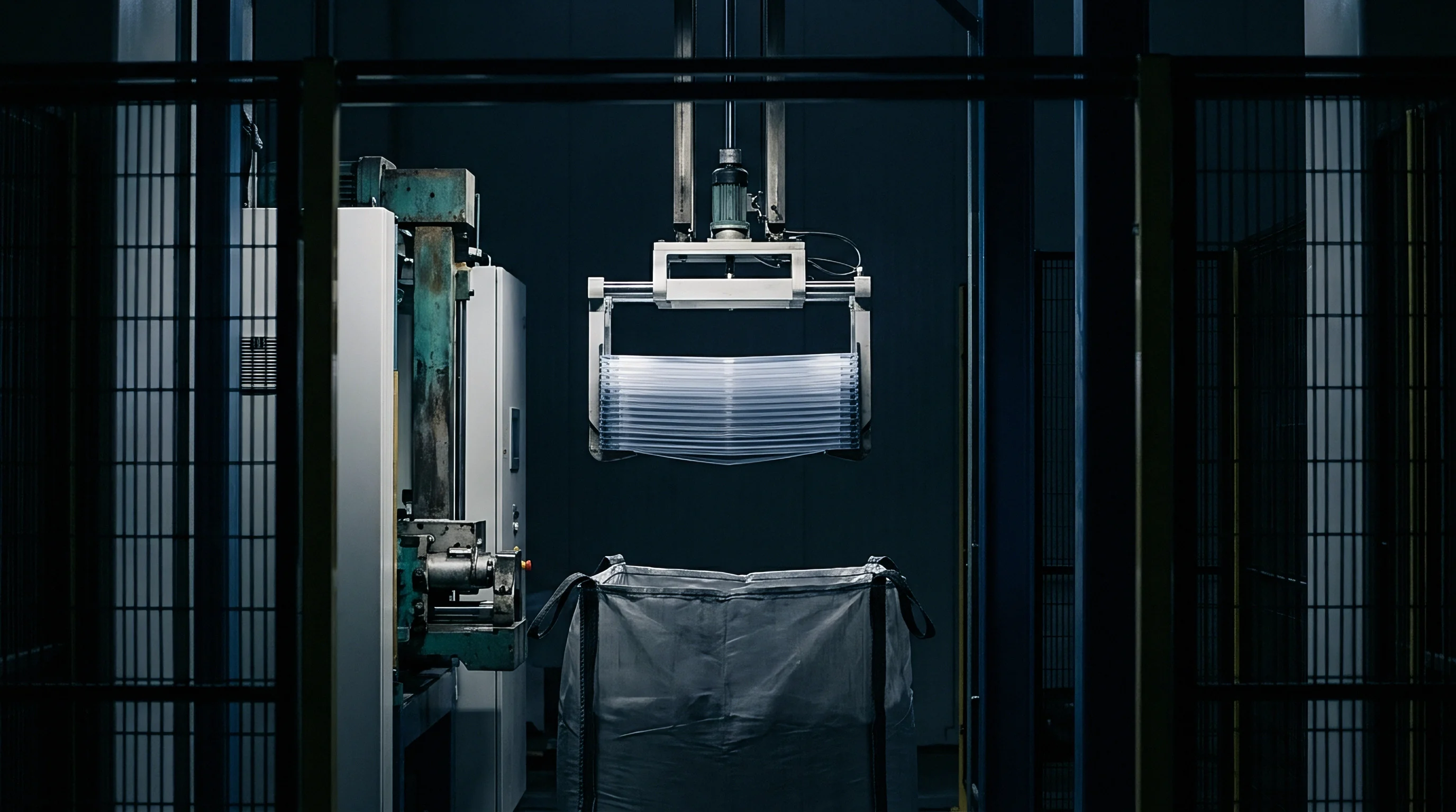
Why Does Deep Sheet Sag Cause Thin Corners?
Deep sag redistributes mass before tooling ever touches the hot polymer. As gravity pulls the middle of the sheet downward into a catenary shape, that central zone undergoes unsupported biaxial stretching. If a male mold ascends or a female tool descends into this sagging web, the central area may have already lost up to 30 percent of its nominal cross-section.
That leaves far less material available to drape across deep cavities and corner radii once plug assist or vacuum forces pull the sheet home.
The pre-stretched central sheet contacts mold features first, chilling upon contact and locking its reduced thickness in place. The remaining unstretched perimeter material must stretch at extreme draw ratios to fill complex corner geometries and deep vertical sidewalls. This unequal mass distribution drives structural failure in high-load areas of thermoformed components.
Correcting this imbalance demands aggressive furnace profiling, where upper and lower heater banks reduce power output in central grid zones while boosting energy delivery along the clamped perimeter frame.
Core temperature equilibrium dictates true biaxial stretch performance more reliably than pyrometer surface readings during high-speed thermoforming cycles.
Webbing defects occur when excess sag creates folds of soft sheet that collapse against each other as the mold closes. When a male tool with multiple adjacent tall projections enters a heavily sagged sheet, the redundant material between projections folds over, forming sealed webs of double-thickness sheet. Preventing web formation requires precise coordination of anti-sag air pressure, mechanical pre-blow inflation, and synchronized mold enclosure speeds.
Pre-blowing the sheet upward into a uniform dome reverses catenary sag, redistributing perimeter material into the central dome structure and providing a uniform wall thickness web for subsequent tool penetration.
Viscoelastic strain recovery complicates sag dynamics during variable cycle interruptions. If a forming station experiences a momentary mechanical delay, extended soak time inside the radiant oven drives sheet temperatures past the rubbery plateau into the viscous flow regime. In this upper processing region, entanglements unbind entirely, transforming elastic strain response into permanent viscous shear flow.
Anti-sag air cushions fail under these conditions, as the melt lacks sufficient extensional yield strength to maintain surface integrity, resulting in sheet tearing and furnace contamination.
Thermal diffusion through heavy amorphous sheet depends on the non-dimensional Fourier number (the product of thermal diffusivity and heating time divided by the square of the sheet half-thickness). Bringing the core within 2 degrees Celsius of the target surface temperature requires a Fourier number of at least 0.45. For an 8-millimeter polycarbonate sheet with a thermal diffusivity of 0.108 square millimeters per second, reaching that equilibrium requires at least 66 seconds of uninterrupted heating under moderate radiant flux.
- Position the optical sag sensor 25 millimeters below the flat sheet line at the geometric center of the clamp frame.
- Profile the radiant oven zones with an inverted parabolic power curve, setting perimeter elements at 85 percent power and central elements at 45 percent power.
- Initiate radiant heating and monitor surface temperature development using dual-wavelength infrared pyrometers set to the 3.4 micrometer polymer absorption band.
- Activate the low-pressure air-puff support system at 0.05 Bar when the sheet breaks the optical sensor beam, maintaining support until the forming cycle triggers.
- Verify thermal core saturation by measuring internal cross-sectional temperatures using destructive thermocouple insertions on test sheet samples.
High radiant power levels yield fast cycle times but widen the temperature delta between sheet surface and sheet core. A multi-stage heating profile mitigates this thermal variance. Initial furnace stages employ high-intensity short-wavelength quartz heaters to drive thermal energy rapidly into the material.
Final soak stages shift to lower-intensity medium-wavelength ceramic elements, allowing conduction to equalize internal thermal gradients without degrading surface aesthetics.
Temperature gradients across the sheet area induce differential stretch resistance during mechanical plug penetration. Sheet regions that are 10 degrees Celsius hotter than adjacent zones exhibit significantly lower yield stresses, absorbing a disproportionate fraction of applied deformation energy. This localized strain concentration creates wall thinning, optical distortion, and reduced impact strength in the finished part.
Thermographic inspection of the heated sheet immediately prior to mold closure identifies these thermal hot spots, enabling process setters to tune individual heating elements to single-percentage power increments.

Biaxial Strain Hardening and Temperature Window Optimization
Biaxial stretching occurs when an amorphous sheet deforms along two orthogonal axes during vacuum, pressure, or plug-assisted thermoforming. The operating window sits within the rubbery plateau between the glass transition and true melt flow. Here, polymer chains deform elastically as backbone segments align between entanglement points.
Total biaxial stress response is a direct function of forming temperature, strain rate, and the applied stretch ratio.
Applying high stretch rates at lower processing temperatures yields elevated orientation stress and strong strain hardening responses. This stress state preserves uniform wall thickness distribution across complex tool geometries. Lowering deformation temperatures brings the sheet closer to its glass transition point, where chain mobility drops significantly.
While this condition yields maximum strain hardening and wall thickness uniformity, it increases the force needed for plug assist drive systems and heightens the risk of internal micro-cracking or stress whitening in rigid amorphous materials like unmodified acrylic or clear polystyrene.
Calculating the strain hardening exponent verifies biaxial stretch performance under rapid vacuum pull-down conditions. Higher stretch temperatures increase chain mobility, allowing entanglements to slip during deformation. This molecular slippage lowers transient extensional viscosity, suppressing the strain hardening exponent.
Under these hot conditions, the polymer behaves more like a viscous fluid than an elastic rubber. The sheet thins rapidly at the point of initial tool contact, resulting in heavy localized wall attenuation and deep corner blowout failures.
Perimeter cooling along clamp frames creates a stiff border that resists deformation during the forming stroke. Clamp frames act as heat sinks, drawing thermal energy away from the sheet perimeter through direct conduction and convection. To compensate for edge losses, process engineers integrate auxiliary thermal zone control along the perimeter of the oven, driving edge heating elements to higher thermal setpoints than the main heating array.
This thermal boosting softens the sheet margin, allowing full draw utilization up to the clamp line.
Uniaxial stretch dynamics differ fundamentally from true biaxial extension. In uniaxial stretching, material contracts freely in transverse dimensions as it elongates along the primary stress vector. In equal-biaxial stretching, surface area expands exponentially while thickness diminishes to conserve overall volume.
Amorphous polymers undergo significant structural strain hardening under biaxial conditions due to planar alignment of chain segments. This planar orientation elevates tensile modulus and impact performance parallel to the sheet plane while reducing shear strength through the thickness direction.
The Deborah number governs viscoelastic response during rapid plug assist strokes, comparing polymer relaxation time to total duration of the mechanical plug stroke. If the plug enters the sheet rapidly, yielding a Deborah number much greater than unity, the polymer responds as an elastic solid, storing mechanical energy and distributing strain broadly across the sheet span. If the plug moves slowly, resulting in a low Deborah number, stress relaxation occurs faster than mechanical displacement, allowing localized viscous thinning directly under the plug tip.
Forming station air management directly impacts stretch dynamics during the final vacuum pull-down phase. Rapid evacuation of the mold cavity creates a sharp pressure differential across the sheet, driving high initial strain rates that can reach 50 reciprocal seconds. If vacuum application occurs prematurely, before mechanical plug assist reaches its final depth, the unsupported sheet drapes uncontrolled against high mold features, creating thick pre-contact zones and starved deep cavities.
Staggering vacuum engagement through proportional valves controls the transient strain rate, matching it to the strain hardening envelope of the specific resin.
Locking vacuum delay timing at 0.4 seconds following plug stroke completion reduces web scrap to under 1.2 percent.
Although sheet thinning in deep drawer features is frequently blamed on radiant furnace calibration, plug material heat transfer and cavity evacuation dynamics exert equal influence.


Yield
Mold geometry dictates local strain distribution, material yield, and final wall thickness variation in thermoformed amorphous components. When a hot polymer sheet drapes over a mold feature, initial contact quenches the sheet surface below its glass transition temperature, freezing its thickness instantly. Subsequent stretching occurs exclusively in the remaining uncontacted regions of the sheet web.
Male mold geometries, where the sheet drapes over protruding tool features, draw material primarily from the apex down toward the base, creating thin top corners and thick base flanges. Female mold geometries pull material from the perimeter down into deep cavity pockets, yielding thick top flanges and extremely thin bottom corners.
Calculating the area draw ratio provides a fundamental baseline for predicting average wall thinning across a given tool design. The area draw ratio compares total internal surface area of the finished mold cavity to the planar footprint area of the open clamp frame span. An area draw ratio of three to one indicates that nominal sheet thickness will diminish to approximately one-third of its original gauge after complete tool engagement.
Local draw ratios in sharp corners, draft angles, and deep ribs deviate dramatically from this average figure, often exceeding five to one in unassisted vacuum drawing operations.
| Mold Cavity Geometry | Area Draw Ratio | Plug Material / Temperature | Nominal Sheet Gauge (mm) | Min Corner Thickness (mm) | Thickness Variance (%) |
|---|---|---|---|---|---|
| Deep Female Box (100mm Depth) | 3.2 to 1 | Syntactic Foam / 120°C | 4.00 | 1.12 | 28.0 |
| Deep Female Box (100mm Depth) | 3.2 to 1 | Aluminum Unheated / 25°C | 4.00 | 0.64 | 16.0 |
| Male Core Tower (150mm Height) | 4.1 to 1 | Syntactic Foam / 135°C | 5.00 | 0.98 | 19.6 |
| Shallow Tray (40mm Depth) | 1.8 to 1 | Delrin Unheated / 25°C | 2.50 | 1.45 | 58.0 |
| Complex Enclosure (Multiple Cavities) | 3.6 to 1 | Syntactic Foam / 130°C | 3.50 | 0.82 | 23.4 |
Plug assist mechanics serve as the primary physical mechanism to redistribute mass before final vacuum clamping occurs. A plug assist tool pushes material mechanically into female cavity spaces, pre-stretching the central sheet span before air pressure or vacuum forces pull the material against cold metal cavity walls. Plug material selection governs thermal boundary conditions at the sheet interface.
Low thermal conductivity materials, such as syntactic foam or engineered thermoplastics, prevent thermal quenching at the plug tip, allowing the sheet beneath the plug to stretch uniformly during penetration.
High thermal conductivity plugs, such as unheated aluminum tools, instantly cool the polymer upon contact. The cold sheet freezes to the plug face, refusing to stretch further. As the plug advances into the cavity, only the uncontacted sheet perimeter between the plug edge and the mold clamp stretches, producing heavy wall thinning along side walls and deep bottom corners.
Using heated syntactic foam plugs maintained within 20 degrees Celsius of the sheet glass transition temperature allows smooth friction slip, permitting sheet material to slide across the plug tip and distribute evenly throughout the deep cavity profile.
Webbing and corner thinning dynamics require precise control over corner radii and draft angles within the mold cavity. Internal and external corner radii must equal at least one to two times initial sheet thickness to avoid extreme localized stress concentrations. Tight corner radii create localized geometric constraints that restrict polymer flow, forcing adjacent unconstrained regions to stretch excessively.
Draft angles of at least 3 degrees for female cavities and 5 degrees for male cores are essential to permit clean part ejection without scraping or introducing residual mechanical stress into rigid amorphous structures.

Corner Radii Stress Concentrations and Structural Yield Limits
Mechanical stress concentration factors increase exponentially as corner radii shrink relative to local wall thickness. When a thermoformed part experiences external impact or structural flexure, stress lines converge around sharp internal radii. For amorphous materials like polycarbonate and polymethyl methacrylate, which exhibit brittle fracture modes under notched impact testing, sharp corner geometries act as structural failure points.
A corner radius under 0.5 millimeters increases local flexural stress by a factor of 2.5 compared to a fully rounded 3.0 millimeter radius under identical load conditions.
Residual thermal stresses frozen into thermoformed sheet stock compound these structural vulnerabilities. Rapid cooling against cold mold surfaces locks oriented polymer chains into non-equilibrium configurations. If mold cooling channel layouts generate thermal gradients across the tool face, differential shrinkage occurs during solidification.
The part exits the mold carrying high internal stress profiles, making it susceptible to delayed warpage, environmental stress cracking, and low-energy brittle failure when exposed to industrial solvents or cleaning agents.
Standard acceptance specs mandate that local wall thinning must not exceed 65 percent of nominal extruded sheet gauge across any functional load-bearing corner radius.
Specifying a tight tolerance band on sheet gauge prevents catastrophic webbing during plug assist penetration. Environmental stress cracking in polycarbonate and acrylonitrile butadiene styrene components occurs when residual tensile stress interacts with aggressive chemical media. Solvents like acetone, toluene, or even localized plasticizer migration from flexible gaskets lower the critical energy threshold needed to initiate crazing.
Crazes develop into micro-cracks under localized tensile loads, propagating rapidly through thin wall sections. Annealing thermoformed parts above their heat deflection temperature releases frozen-in orientation stress, restoring environmental crack resistance at the cost of secondary processing equipment and cycle time.
Vacuum vent hole geometry and distribution dictate local surface quality and evacuation speed. Vacuum vents placed near internal corner radii must feature diameters smaller than 0.8 millimeters for light-gauge sheet, or 1.2 millimeters for heavy-gauge sheet, to prevent hot polymer melt from creeping into vent orifices. Melt entry forms surface pimples or dimples, creating local stress risers that degrade fatigue life.
Slot vents cut along structural mold partings provide superior air evacuation rates without leaving discrete surface marks, accelerating final sheet pull-down and improving surface replication of complex mold textures.
Mold cooling design directly controls processing cycle times and dimensional stability of extruded sheet products. Aluminum tooling, possessing thermal conductivity ratings near 160 Watts per meter-Kelvin, conducts heat away from the soft polymer sheet rapidly compared to composite or epoxy tooling. Coolant channels drilled within 25 millimeters of the mold surface maintain uniform tool face temperatures within plus or minus 2 degrees Celsius across the forming area.
Uneven cooling creates localized variations in post-mold thermal contraction, driving part warpage and dimensional deviations that breach print tolerances.
Part ejection systems must distribute mechanical forces uniformly across the formed profile to avoid distorting thin, warm wall sections. Stripper plates, pneumatic poppet valves, and mechanical ejector pins must engage only after the sheet cools below its heat deflection temperature. Ejection of amorphous parts at elevated temperatures induces localized plastic yield, generating permanent distortion, edge stress lines, and optical haze.
Integrating air-assist ejection circuits introduces a high-pressure air cushion between the tool and the plastic part, breaking vacuum adhesion cleanly without stressing thin corner geometries.
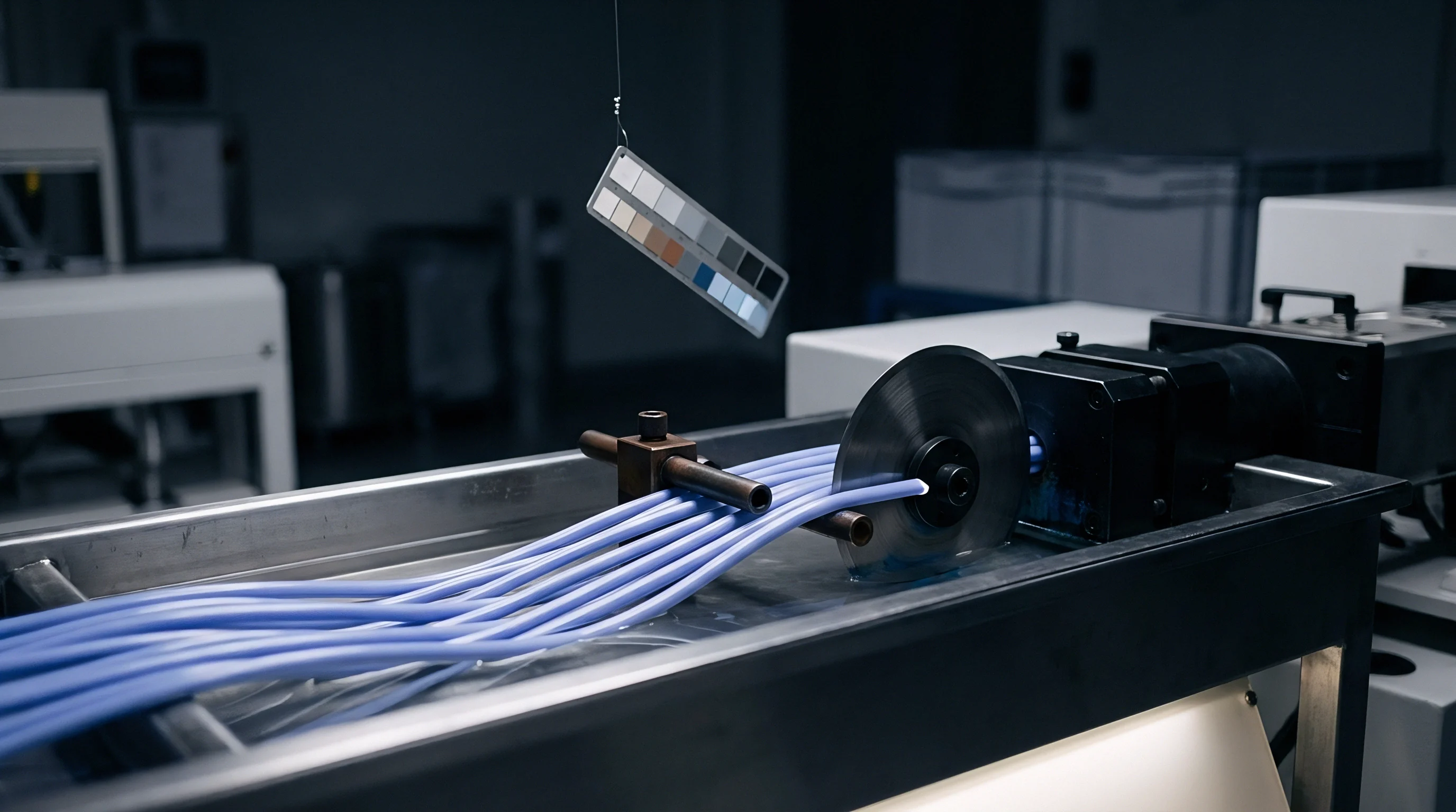
Commercial Tooling Specifications and Scrap Rate Economics
Tooling investment decisions hinge on the relationship between cavitation count, sheet nesting efficiency, and total production volume. Broad sheet extrusion lines feed thermoforming operations through either continuous roll-fed processes or discrete sheet-fed operations. Continuous roll-fed machinery maximizes throughput for sheet gauges under 1.5 millimeters, running at speeds up to 40 cycles per minute.
Heavy-gauge applications exceeding 3.0 millimeters rely on discrete sheet-fed shuttle or rotary machines, where cycle times range from 40 seconds to over two minutes per drop.
Sheet width utilization establishes the core economic floor for high-volume thermoforming operations. Skeleton scrap, the unformed sheet web locked beneath the clamp frame perimeter, represents direct material waste that must be recovered through grinding and re-extrusion. In a multi-cavity tool layout, poor cavity spacing increases skeleton scrap ratios to over 40 percent of total extruded sheet weight.
Optimizing cavity layout and minimizing web gaps down to 15 millimeters reduces edge scrap, lowering landed part costs while maintaining structural frame rigidity during high-pressure plug assist strokes.
Regrind integration into primary extrusion feed streams introduces significant rheological and commercial variability. Reprocessing thermoformed skeleton scrap subjects the polymer to multiple heat histories, driving thermal degradation, chain scission, and yellowing. In high-impact polystyrene and acrylonitrile butadiene styrene, repeated extrusion cycles degrade the elastomeric rubber phase, lowering notched Izod impact strength.
Virgin-to-regrind blending ratios must be tightly controlled through loss-in-weight gravimetric blenders, capping virgin replacement at a maximum of 30 percent by weight to prevent shifts in zero-shear viscosity and sheet sag characteristics.
Amorphous sheet thickness variations propagate directly into final part pricing through raw material consumption and cycle time penalties. If an extrudate exhibits a thickness tolerance band of plus or minus 8 percent, process engineers must set nominal sheet gauge to the upper limit to ensure that the thinnest drawn corners satisfy minimum structural print requirements. Over-specifying sheet thickness to compensate for extrusate gauge variation adds unrecoverable material cost to every production lot, while extending radiant furnace heating cycles and mold cooling times proportionately.
Procuring high-precision optical continuous sheet gauge monitoring systems reduces extrusion thickness variance to within plus or minus 1.5 percent. This precise gauge control allows engineers to trim nominal sheet thickness settings, yielding an immediate raw material savings of 5 percent to 8 percent across high-volume production runs. Capital expenditure for inline beta-gauge or ultrasound profiling hardware recovers its investment within months through reduced resin usage and compressed thermoforming furnace soak cycles.
Tooling construction material decisions directly govern production longevity and piece price economics. Machined aircraft-grade aluminum tooling (such as 6061-T6 or 7075-T6) provides near-infinite tool life for vacuum and pressure forming applications, maintaining precise dimensional tolerances over hundreds of thousands of cycles. Cast aluminum tooling offers a lower initial capital cost for large-scale structural parts, but suffers from internal porosity, lower thermal conductivity, and vulnerable corner radii that degrade under repeated mechanical plug impacts.
For prototype runs under 500 units, high-density polyurethane tooling boards provide low-cost geometry validation, though their low thermal conductivity extends cycle cooling times by over 200 percent.
Part rejection criteria must explicitly define acceptable limits for wall thinning, optical distortion, surface micro-voids, and post-mould warpage. Standard industrial supply agreements enforce a strict quality clause: local wall thinning shall not exceed 60 percent of nominal sheet thickness, and post-mould warpage must remain within 0.5 percent of maximum linear part dimensions when measured after 24 hours of environmental equilibration. Incorporating these precise metrics into the tooling sign-off contract prevents commercial disputes regarding structural yield failures and establishes clear accountability for tool modification expenses.
The supply contract stipulates that any tool failing to hold dimensional tolerances within DIN 16742 TG6 across a continuous 5,000-unit qualification run at agreed cycle speeds shall be re-machined or replaced entirely at the toolmaker’s sole expense.