Decoupled Injection Moulding Process Optimization via Cavity Telemetry
Cavity pressure telemetry decouples polymer melt behavior from machine hydraulics, locking peak pressure to eliminate scrap and stabilize part dimensions.


Gate
A polymer melt behaves quite differently once it enters the thin channels of a hardened tool. Machine-side parameters like hydraulic pressure, screw position, and barrel temperature offer only indirect control over melt front progress. Polymer compressibility inside the barrel, backflow through the non-return valve, and lot-to-lot variations in melt flow rate decouple hydraulic motion from cavity filling.
Setting process switchover strictly by screw displacement leads to dimensional drift, sink marks, or flash whenever resin viscosity shifts. Cavity telemetry isolates the actual pressure and thermal profile inside the mold steel, providing direct visibility into the rheological events that dictate part geometry.
Decoupled molding protocols break the injection cycle into distinct phases defined by specific physical goals. Decoupled I uses high-speed velocity to fill ninety-five percent of the cavity without applying packing pressure, keeping the melt moving fast enough to minimize frozen skin layer growth. Decoupled II adds a pressure transfer point based on screw position, followed by a controlled pack phase to finish filling the part and account for volumetric shrinkage.
Decoupled III drops screw position transfer altogether for direct cavity pressure measurement, switching from fill speed to pack pressure the moment polymer melt arrives at a set sensor location in the cavity.
Hydraulic pressure variations of six percent produce cavity pressure swings exceeding eighteen percent during high-speed injection of unfilled polypropylene.
Because pseudoplastic polymers shear-thin, injection speed directly dictates apparent viscosity. Running the stroke under closed-loop velocity control maintains consistent shear rates shot after shot, while machine hydraulic pressure adjusts on the fly to hold screw speed against flow resistance. Switching to pack pressure by position ignores non-return valve leakage, which routinely varies between two and eight percent of total stroke volume.
These screw cushion fluctuations change the actual volume delivered into the runner, causing peak cavity pressure to drift over a shift.

Separating Machine Hydraulics from Cavity Physics
Press-side readings mask what happens inside tool channels. Hydraulic sensors measure fluid force behind the ram, combining mechanical friction, screw inertia, nozzle resistance, runner pressure drop, and cavity resistance into a single figure. Cavity telemetry cuts through that hydraulic and mechanical noise by measuring force directly inside the part footprint.
The resulting data reflects actual polymer density and thermal relaxation inside the steel.
Changes in regrind percentage, recycled blends, or resin lots alter polymer chain length distribution and shift viscosity without warning. A five-degree drift in melt temperature shifts viscosity enough to change the pressure drop through the gate. When presses switch over on stroke position, thinner melt fills faster and packs tighter under a fixed hydraulic profile, driving up part weight and flashing parting lines.
Thicker melt under that same profile leaves short shots and voids.

The Three Stages of Decoupled Processing
Decoupled injection strategies bring mechanical discipline to press setup by systematically stripping out machine-dependent variables.
- Decoupled I Phase isolates high-speed filling driven strictly by volumetric velocity, leaving five percent open volume to protect parting lines from hydraulic shock.
- Decoupled II Phase adds controlled hydraulic packing to finish filling the cavity and hold pressure until the gate freezes, decoupling fill speed from shrink compensation.
- Decoupled III Phase switches from fill to pack using real-time transducer signals at end of fill, taking cushion variations and viscosity shifts out of part weight equations.
Direct telemetry makes Decoupled III control practical across complex mold shapes. Placing piezoelectric sensors behind ejector pins or flush in the cavity wall near the end of fill gives the controller immediate feedback when melt arrives. Switchover happens within milliseconds of hitting the voltage threshold, holding peak cavity pressure steady shot after shot despite hydraulic variations or resin batch inconsistencies.
Steel cut once stays cut, and cavity pressure dictates final density. Setting injection speed from rheological curves pinpoints the flat region where velocity changes produce minimal viscosity shifts. Operating on this flat plateau stabilizes fill times and lowers internal stress in the molded part.
Decoupled processing locks fill velocity independent of pack force, so process technicians can fine-tune part weight without disturbing melt front kinetics.
Replacing a collapsed core block cost thirty-two thousand dollars after hydraulic over-packing went unnoticed during a forty-eight-hour unattended weekend run.


Sensor
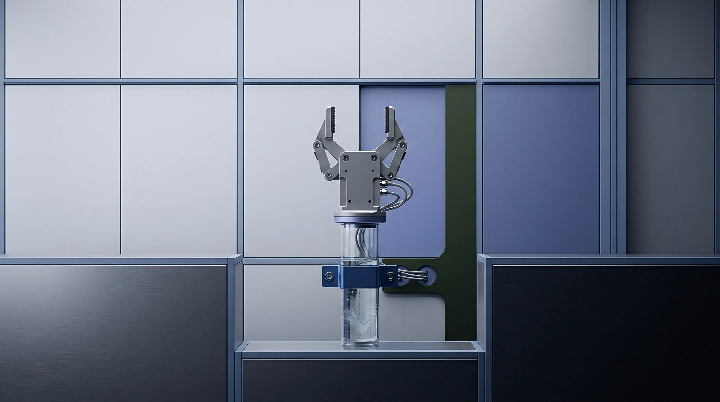
Capturing conditions inside a sealed tool requires sensors that survive two thousand bar of pressure and melt temperatures over three hundred degrees Celsius. Piezoelectric quartz transducers are standard for cavity telemetry thanks to their high stiffness, small size, and microsecond response times. Applying force to synthetic quartz generates an electrical charge strictly proportional to load, which charge amplifiers convert from picoCoulombs into standard industrial voltage signals for the press PLC.
Indirect sensors use standard ejector pins to transmit force to quartz elements mounted in the ejector plate. Direct sensors expose a flush titanium or tool steel diaphragm directly to the melt stream in the cavity wall. Choosing between direct and indirect setups comes down to cosmetic requirements, available tool space, and maintenance access.
Indirect pins leave a slight impression on the part, while direct sensors leave a faint circular witness mark.

Hardware Architectures for In-Mould Measurement
Strain gauge sensors offer an alternative approach, using thin-film resistor bridges bonded to a deflection membrane. They require excitation voltage and output low-millivolt signals that resist cable insulation leakage better than high-impedance piezoelectric lines. However, piezoelectric sensors offer higher mechanical stiffness, minimizing deflection under load and keeping plastic from flashing into clearance gaps around the transducer face.
| Sensor Architecture | Pressure Range (bar) | Max Temp (Celsius) | Response Time | Typical Lifespan (Cycles) |
|---|---|---|---|---|
| Direct Piezoelectric | 0 to 2500 | 350 | < 1 microsecond | 10,000,000 |
| Indirect Piezoelectric Pin | 0 to 2000 | 200 | < 2 microseconds | 5,000,000 |
| Direct Strain Gauge | 0 to 1500 | 200 | < 10 milliseconds | 2,000,000 |
| Infrared Optical Pyrometer | N/A (Temp Only) | 400 | < 5 milliseconds | 3,000,000 |
Optical telemetry uses fiber-optic conduits mounted flush with the cavity wall to measure infrared radiation from the melt. Infra-red pyrometry captures true melt temperature in real time without affecting part finish or mechanical ejection. Combining pressure and thermal data lets monitoring systems calculate real-time cooling rates and melt front velocity during fill.
Installation Mechanics and Pin Placement Protocol
Installing transducers requires precise pocket machining in the tool steel blocks. Ejector pin clearance bores must hold zero point zero zero five millimeter tolerances so plastic cannot leak past the pin and bind the assembly. Backing plates require rigid support to stop sensor deflection under high packing pressures, and wiring through water manifold plates needs armored conduit to shield cables from compression and moisture.
- Bores for ejector pins driving indirect transducers are ground to an H7/g6 sliding fit tolerance along the full length of the cavity plate.
- Sensor pockets behind ejector pins are counter-bored flat within zero point zero zero two millimeters total indicator reading across the bottom surface.
- Pre-load calculations are applied using calibrated shims so initial force sits on the quartz element without binding the pin.
- Armored coaxial cable is routed through milled channels clear of cooling lines and slide retainers, clamped with brass fittings every hundred millimeters.
- Charge amplifiers are calibrated across multiple points on hydraulic test fixtures before connecting to press control boards.
Toolmakers regularly place sensors right next to cooling lines, creating thermal gradients that drift the signal baseline. Backing button alignment determines how efficiently force transfers from the ejector pin face to the quartz crystal. Off-center loads create bending moments across the quartz disks, causing false pressure spikes and early sensor fatigue.
A transducer mounted directly behind a moving ejector pin captures thermal expansion effects alongside melt compression.
Cable insulation integrity determines measurement accuracy in piezoelectric systems. High-impedance cables carrying picoCoulomb charges lose signal fidelity quickly if oil, water, or fingerprint grease hits connector pins. Cables must maintain insulation resistance above ten to the thirteenth power ohms, while low-noise coaxial lines prevent triboelectric noise caused by press vibration during mold opening.
Signal drift occurs when ambient shop floor temperatures fluctuate by five degrees during a shift.


Transience
Dynamic pressure curves recorded in the cavity show exact polymer behavior from the moment melt passes the gate until the part freezes. A standard trace breaks down into three distinct zones: fill ramp, pack plateau, and cooling decay curve. Fill ramp slope reflects injection speed and flow resistance through the gate, while pack plateau height marks the maximum force applied to the solidifying plastic.
Analyzing peak pressure timing uncovers subtle flow imbalances in multi-cavity tools. Comparing arrival times between post-gate and end-of-fill transducers gives local fill velocity. A sharp pressure spike at the end-of-fill sensor signals volumetric saturation; switching to pack pressure just before this spike protects the mold from hydraulic shock, while switching late forces parting lines to absorb steel deflection forces.

Deconstructing the Cavity Pressure Curve
The area under the cavity pressure curve ~ the pressure-time integral ~ is the primary statistical metric for predicting part weight. Changes in this integral correlate directly with part mass, sink marks, and final volumetric shrinkage. Watching the decay slope during cooling reveals gate seal timing.
Once the gate freezes solid, cavity pressure drops purely as a function of thermal contraction inside frozen skins.
| Pressure Curve Metric | Process Phase | Target Control Variance | Associated Part Defect Mode |
|---|---|---|---|
| Fill Pressure Ramp Slope | Filling Phase | +/- 2.5 Percent | Jetting, Melt Hesitation, Weld Line Weakness |
| Peak Cavity Pressure | Switchover Point | +/- 1.5 Percent | Part Flash, Dimensional Over-sizing, Sticking |
| Pack Plateau Integral | Packing / Holding | +/- 1.0 Percent | Sink Marks, Internal Voids, Volumetric Shrinkage |
| Cooling Decay Rate | Cooling Phase | +/- 3.0 Percent | Part Warpage, Ejection Distortion, Post-Mold Creep |
Gate seal testing uses progressive pack-time increments while monitoring cavity pressure decay curves. Plotting pressure retention against pack time identifies the exact second the gate solidifies. Holding hydraulic pressure past gate freeze wastes power, extends cycle time, and adds thermal stress to the runner.
Dropping pack pressure before gate seal allows pressurized melt to backflow into the runner, causing sink marks and lost part mass.

Real-Time Viscosity Monitoring and Batch Drift
Resin viscosity shifts during production runs change the pressure integral even when machine hydraulic settings remain static. Changes in melt flow rate from regrind adjustments alter energy loss through the runner system. Telemetry software calculates effective viscosity for every shot by dividing the hydraulic pressure integral by cavity pressure arrival time, triggering real-time alarms before dimensions drift out of process control limits.
Screw tip non-return valves wear down over time from glass fibers or mineral fillers. As check rings wear, backflow increases during fill, lengthening fill time and dropping peak cavity pressure. Tracking peak pressure trends across shifts separates machine wear from resin batch variations, providing clear maintenance schedules for injection unit overhauls.
Thermal inertia delays cooling, while peak pressure dictates shrinkage. Heat build-up in uncooled core pins slows local skin formation, delaying structural rigidity before ejection. Temperature sensors near critical cores catch thermal saturation, warning operators if cooling water flow drops or scale builds up inside internal channels.
When the cavity pressure peak shifts left while hydraulic peak pressure climbs, the resin batch is growing stiffer and requires higher thermal energy to fill.
Discipline
Closed-loop injection control feeds the cavity pressure signal straight to the press controller to trigger volumetric switchover. Replacing screw position limits with transducer voltage thresholds stabilizes part mass across ambient and raw material shifts. Transducers feed high-speed converters sampling over one kilohertz, letting the PLC initiate valve shifting within two milliseconds of hitting threshold.
Multi-cavity tools require active transducer management to maintain flow balance across all impressions. Putting sensors in every cavity gives a continuous view of runner manifold imbalances. In hot runner tools, cavity pressure signals feed valve gate circuits directly, driving individual needle valves off local pressure build-up rather than master screw position.

Is Real-Time Cavity Switchover Feasible in Multi-Cavity Tooling?
Balancing high-cavitation tooling through cavity pressure means picking an accurate master cavity or processing data across multi-channel signal processors. Using a single transducer for master switchover on a thirty-two cavity tool means runner imbalances cause unmonitored cavities to see different peak pressures. Managing this imbalance requires placing sensors in the first-to-fill and last-to-fill cavities, bounding overall tool balance within a set process envelope.
- Master Cavity Switchover triggers pack transfer from the slowest-filling cavity, preventing short shots in remote mold locations.
- Average Pressure Thresholding sums multi-channel transducer inputs to switch press phases based on total volumetric saturation.
- Sequential Valve Gating fires individual hot runner needle valves as melt hits transducers placed just downstream of each gate.
- Cavity-Specific Pack Decoupling adjusts individual valve gate closing times to equalize peak packing pressure across non-uniform geometries.
Closed-loop systems maintain stable part quality by adjusting pack pressure on shot N plus one based on peak pressure deviations recorded during shot N. If resin viscosity drops and peak cavity pressure rises above target, the control algorithm trims hydraulic pack pressure on the next cycle to hold part density inside tolerance.

Stabilizing Volumetric Shrinkage across Shift Boundaries
Tight dimensions under DIN 16742 require strict control over volumetric shrinkage throughout extended runs. Temperature swings between cold night shifts and hot afternoons alter steel temperature and hydraulic oil viscosity. Cavity telemetry eliminates this ambient drift by holding cavity packing profiles constant regardless of machine heating or press temperature swings.
Process boundaries create automated scrap sorting without manual inspection. Parts with peak pressure or pack integrals outside statistical limits drop directly into a scrap chute via press-mounted robotics, catching defects at the machine before non-conforming parts reach downstream assembly.
Standard purchasing agreements under ISO 16742 Class TG4 append cavity pressure traces to lot acceptance records, making missing telemetry data grounds for immediate batch rejection.

Economics
Adding telemetry hardware to a multi-cavity mold changes upfront tooling capital and long-term unit production costs. Sensor hardware, pocket machining in hardened steel, signal conditioning, and press integration add between eight thousand and thirty-five thousand dollars to initial tooling invoices. Amortizing that cost over high-volume runs shows clear savings from scrap reduction, cycle optimization, and reduced setup waste.
Cost recovery comes down to scrap reduction achieved through closed-loop control. Medical molding lines under strict quality mandates often run three to five percent scrap during startup and resin transitions on standard hydraulic control. Cavity telemetry drops steady-state scrap under zero point two percent, yielding direct material savings on expensive resins like polyetheretherketone or polysulfone.

Capital Expenditure against Scrap Reduction ROI
Quantifying return on sensor retrofits means accounting for faster setups and avoided tool damage along with resin savings. Parting line flash from over-packing crushes land areas, leading to unplanned toolroom maintenance and downtime. Setting peak pressure limits protects mold steel from over-pressurization, extending maintenance intervals from five hundred thousand to over two million cycles.
| Cost Parameter | Conventional Machine Control | Cavity Telemetry Control | Net Financial Variance |
|---|---|---|---|
| Initial Tooling & Equipment Cost | $85,000 | $108,000 | +$23,000 (Upfront Capital) |
| Resin Scrap Rate (PA66 30% GF) | 4.2 Percent ($18,900) | 0.3 Percent ($1,350) | -$17,550 (Material Savings) |
| Cycle Time (Cooling Optimized) | 24.5 Seconds | 21.0 Seconds | -3.5 Seconds (14.2% Faster) |
| Total Press Machine Hour Cost | 680.5 Hours ($61,245) | 583.3 Hours ($52,497) | -$8,748 (Machine Time Savings) |
| Unscheduled Mold Maintenance | $12,000 (3 Interventions) | $2,500 (0 Interventions) | -$9,500 (Maintenance Savings) |
| Net Landed Cost per Good Part | $0.1771 | $0.1643 | -$0.0128 (7.2% Unit Savings) |
Scientific gate seal analysis using pressure decay curves often exposes padded cooling times on legacy process sheets. Safely cutting three seconds off a twenty-four-second cycle increases production capacity by twelve point five percent, deferring capital expenditure on additional presses and tooling.

Cycle Time Compression and Capacity Optimization
Moving to cavity pressure transfer cuts scrap by four percent. Savings accumulate quickly on high-cost engineering polymers where regrind is banned by regulation. Sensor costs drop to fractions of a cent per part within six months of continuous production, turning initial capital expenditure into lasting margin improvement.
Writing cavity telemetry into tooling purchase specs ensures mold builders prepare sensor pockets during initial tool design rather than retrofitting hardened steel plates later. Tooling specs should define clear cabling standards, connector mounting locations, and signal validation procedures before tool sign-off.
Tooling specification dossiers must detail hardware integration rules before steel cutting begins.
- Transducer Pocket Tolerances mandate pocket depth precision within zero point zero zero two millimeters and backing plate surface finish under Ra zero point two micrometers.
- Connector Box Standards require heavy-duty industrial multi-pole housings mounted flush to the outer mold frame away from crane lifting points.
- Signal Wiring Separation specifies isolated conduit paths for sensor signals, routed clear of high-voltage hot runner heater lines.
- Pre-Delivery Signal Check requires toolmakers to submit static hydraulic calibration certificates verifying transducer output across the operating temperature range.
Operators frequently pad cooling times by five to ten seconds to stay safe on difficult parts. Real-time telemetry shows exact gate freeze timing, stripping phantom cooling seconds out of the cycle while keeping full dimensional compliance under DIN 16742.
Whether third-party toolrooms will absorb sensor installation risks without raising initial tooling quotes remains an unsettled commercial friction in regional supply chains.


Qualification
Validating a new injection mold with internal pressure instrumentation replaces visual sampling with hard process boundary data. IQ, OQ, and PQ procedures use cavity telemetry to establish true process windows. Plotting peak cavity pressure against injection speed generates a matrix defining upper and lower specification limits for good parts.

Scientific Moulding Dossier Construction
Building a robust qualification dossier takes controlled Design of Experiments runs while logging cavity pressure metrics. Varying melt temperature, injection speed, pack pressure, and cooling time across high-low bands uncovers process sensitivities. Telemetry captures parameter interactions that standard press monitoring misses, helping establish Cpk capability indexes above one point six six on critical dimensions.
Melt viscosity changes occurring mid-shift render machine stroke position useless as a control variable for part weight.
Operational Qualification protocols require testing process robustness under simulated viscosity shifts. Adding ten percent high-flow regrind or shifting barrel temperatures tests the control algorithm’s ability to hold peak cavity pressure on target. A validated Decoupled III process adjusts machine hydraulics automatically, holding dimensions inside drawing tolerances without technician intervention.

Verifying Dimensional Capability and Long-Term Tool Health
Long-term performance qualification relies on comparing original baseline pressure curves against traces from production runs. Baseline shifts indicate mechanical wear, fouled cooling channels, or sensor drift. Tracking decay rates over time alerts tooling engineers to core pin wear, vent clogging, or parting line collapse long before off-spec parts hit final inspection.
Telemetry records provide indisputable proof of tool maintenance and operating history. When disputes arise between molders and brand owners over tool damage or non-conformance, archived pressure logs prove whether failure came from hydraulic over-packing or bad steel heat treatment.
Production sign-off completes once the master peak pressure envelope is saved to press memory and locked against manual overrides on the floor.