Predictive Thermal Resistance Modeling for Chemical Texture Etching Tolerances in Multi Cavity Injection Molds
Predictive thermal resistance modeling balances multi-cavity heat extraction across textured tool inserts to hold tight DIN 16742 tolerances.


Flux

Transient Heat Flow across Chemical Topography
When molten polymer contacts a steel cavity surface, thermal energy transfers rapidly from the fluid melt into the metal tool wall. In a smooth cavity polished to an SPI-A2 finish, microscopic surface asperities remain under two hundred nanometers, establishing near-perfect mechanical contact once internal pressure rises above twenty megapascal. Chemical textures present a fundamentally different thermal interface.
Etched patterns create peak-to-valley micro-topographies ranging from fifteen micrometers for light satin finishes up to one hundred twenty micrometers for deep leather grains. As the polymer skin freezes against these etched micro-structures, air pockets remain trapped in the microscopic valleys of the texture. Air possesses a thermal conductivity near zero point two four Watts per meter-Kelvin, acting as an insulating barrier compared to tool steels like P20 or H13, which exhibit thermal conductivities between twenty-four and twenty-nine Watts per meter-Kelvin.
The rate of heat transfer through this textured zone dictates initial skin formation and the molding’s subsequent volumetric shrinkage. Solidification dynamics depend directly on the local interfacial heat transfer coefficient. During filling, molten plastic fills the primary cavity quickly, but high melt viscosity prevents full penetration into the fine sub-micron asperities of an acid-etched texture.
This incomplete micro-conformance creates a thermal resistance layer. Effective thermal resistance at the boundary scales directly with average etch depth and inversely with applied packing pressure. At low packing pressures below fifteen megapascal, microscopic contact area drops below forty percent of the nominal geometric surface area.
Thermal energy must conduct through discrete points of polymer-steel contact while bridging trapped gas pockets via radiation and low-efficiency gas conduction. The localized temperature gradient across this region remains steep, retarding the overall cooling rate of the part skin.
Cooling delays alter the semi-crystalline polymer structure near the surface. In materials such as polypropylene or polyamide, slower localized cooling allows higher crystallinity to develop near deep texture valleys. Regions contacting shallow asperities freeze rapidly, producing an amorphous or low-crystallinity skin layer.
These microscopic structural variations induce localized yield strength shifts and post-molding dimensional variation. Heat extraction rates across textured steel govern part geometry long before the clamp opens.
Air pockets trapped within deep chemical etch valleys retard thermal conduction long before polymer skin reaches solidification temperature.

Interfacial Contact Resistance Mechanisms under Cavity Pressure
Pressure within the mold cavity acts as the primary driving force overcoming interfacial thermal resistance. During the packing and holding phases of the injection cycle, hydraulic pressure forces the softening polymer skin into closer contact with the etched steel micro-profile. Higher cavity pressure compresses trapped micro-air pockets and expands real contact area between polymer and steel.
Contact dynamics follow non-linear behavior across three distinct process regimes. In the initial filling phase, contact pressure remains low, below ten megapascal, yielding interfacial thermal conductance values between four hundred and eight hundred Watts per square meter-Kelvin. As packing pressure ramps up to forty megapascal, the polymer deforms viscoelastically into the texture valleys, causing interfacial conductance to jump to two thousand five hundred Watts per square meter-Kelvin.
Beyond fifty megapascal, microscopic contact area saturates as air trapped in texture roots reaches maximum compression, plateauing interfacial conductance around three thousand two hundred Watts per square meter-Kelvin.
Thermal contact conductance depends on the yield stress of the polymer skin at elevated temperatures. As heat transfers into the tool, skin temperature drops rapidly toward the glass transition temperature or crystallization point. This drop increases the mechanical shear modulus of the skin, resisting further micro-deformation into the chemical texture.
The process window to achieve maximum thermal contact closes within milliseconds of cavity fill.
Modeling this interfacial resistance requires decoupling constant tool steel conduction properties from dynamic boundary conditions at the cavity wall. Traditional injection molding simulations apply a uniform, fixed heat transfer coefficient across all mold surfaces, typically set around two thousand Watts per square meter-Kelvin. That simplifying assumption fails when analyzing multi-cavity tooling with complex textured surfaces.
A variance of ten micrometers in etch depth across adjacent cavity inserts alters local thermal conductance by twenty to thirty percent during the critical packing window. Predictive thermal models must calculate thermal resistance directly as a function of local etch depth, instantaneous cavity pressure, and temperature-dependent polymer skin modulus. Chemical etch topography alters thermal boundary conditions predictably across every square millimeter of cavity surface area.

Etch

Acid Attack Dynamics on Tool Steel Alloys
Chemical texturing relies on controlled acid reaction rates to dissolve selected microscopic domains of the mold cavity surface. Toolmakers apply photoresist masks or protective ground coatings before submerging or spraying cavity inserts with acid baths containing ferric chloride, nitric acid, or hydrofluoric acid formulations. The acid preferentially dissolves the steel’s iron matrix, exposing hard carbide phases and creating a randomized micro-topography of plateau peaks, micro-slopes, and valleys.
Different steel alloys react unevenly to identical etching parameters. P20 steel (1.2311 or 1.2738), a pre-hardened chrome-moly alloy widely used in medium-run tooling, contains sulfur additions to enhance machinability. These manganese sulfide inclusions act as high-energy corrosion sites during chemical etching, resulting in micro-pits and localized variations in etch depth.
H13 hot-work tool steel (1.2344), vacuum-degassed and heat-treated to forty-eight Rockwell C, exhibits far higher micro-structural homogeneity. Etch attack rates on H13 proceed evenly across the grain structure, producing repeatable texture depth profiles with lower statistical variance across multiple inserts. NAK80 precipitation-hardened steel yields ultra-fine texture definition thanks to its uniform nickel-aluminum-copper matrix, free from large primary carbide clusters.
Dissolving metal under acid spray systems introduces processing variables that alter texture geometry. Acid temperature, Baumé concentration, spray pressure, and bath flow velocity change the chemical dissolution rate dynamically. A temperature rise of two degrees Celsius in a ferric chloride bath increases metal removal rates by six percent.
In multi-cavity tooling, etching eight or sixteen separate cavity blocks sequentially within the same bath causes depth drift between the first insert etched and the final insert etched unless bath parameters remain strictly controlled.
Variations in micro-roughness alter the physical thermal resistance presented to the polymer melt. Etch depth defines the maximum vertical distance between peak and valley, while peak density measures the spatial frequency of micro-aspirations per unit area. High peak density with shallow depth allows polymer skin to span across peaks, trapping continuous micro-air sheets.
Low peak density with deep valleys permits deeper polymer flow into the texture, increasing total contact surface area but introducing severe mechanical undercuts that resist part ejection. Etch geometry directly establishes the thermal boundary parameters of the cavity wall.

Micro-Depth Variances across Multi Cavity Tool Plates
Toolmakers targeting standardized textures like Mold-Tech MT-11010 aim for a nominal etch depth of twenty-five micrometers. Industrial manufacturing tolerances for chemical texturing routinely accept a variance band of plus or minus five micrometers across a single cavity block. Across an eight-cavity or sixteen-cavity tool plate, cumulative etch depth variations frequently span thirty percent of nominal texture depth due to process drift in acid concentration, manual mask application differences, and flow turbulence inside complex cavity geometry.
Spatial location within a multi-cavity plate compounds etch inconsistency. Cavities located near the center of a large tool plate receive identical acid bath exposure times during submersion etching, but agitation velocities around edge cavities often differ, changing the local boundary layer thickness of the acid solution. Edge cavities end up with a higher removal rate, yielding deeper texture profiles with sharper micro-peak radii.
Center cavities receive lower fluid turnover, producing shallower etch profiles with rounded micro-peaks. The physical consequence surface texture variation extends beyond cosmetic appearance, directly governing thermal contact resistance during mold cooling.
| Tool Steel Substrate | Texture Standard | Nominal Etch Depth (µm) | Peak Density (peaks/mm²) | Thermal Conductance at 15 MPa (W/m²K) | Thermal Conductance at 40 MPa (W/m²K) |
|---|---|---|---|---|---|
| P20 (1.2738) Pre-hardened | MT-11010 | 25.0 ± 4.5 | 140 ± 18 | 650 | 2100 |
| P20 (1.2738) Pre-hardened | MT-11050 | 75.0 ± 8.0 | 65 ± 12 | 420 | 1450 |
| H13 (1.2344) Premium ESR | MT-11010 | 25.0 ± 2.0 | 165 ± 10 | 820 | 2650 |
| H13 (1.2344) Premium ESR | VDI 24 | 18.0 ± 1.5 | 210 ± 14 | 980 | 2950 |
| NAK80 (Precipitation Hard) | MT-11010 | 25.0 ± 1.2 | 180 ± 8 | 890 | 2800 |
| 7075-T6 Aluminium Insert | VDI 30 | 32.0 ± 5.0 | 110 ± 15 | 540 | 1850 |
Depth variance shifts local thermal dissipation performance. A cavity insert with a twenty micrometer etch depth reaches full plastic-to-metal contact early in the packing phase, establishing rapid heat transfer. An adjacent insert with a thirty-five micrometer etch depth retains trapped air layers longer, reducing heat flux out of the melt skin.
As a result, polymer solidification proceeds asymmetrically across the mold plate. Parts in shallow-etched cavities cool faster, shrink earlier, and freeze their gates ahead of parts in deep-etched cavities. The metal finish governs thermal extraction rates across multi-cavity layouts.
Chemical texturing shops typically blame variation on incoming steel batch inconsistencies or manual mask application. Yet toolroom audits show that manual washing and masking protocols account for nearly half of all cavity-to-cavity texture depth discrepancies.


Boundary

Mathematical Formulation of Pressure Dependent Thermal Conductance
Modelling thermal behavior in injection molding requires precise boundary conditions at the contact interface between polymer melt and tool steel cavity wall. Classical thermal models assume an infinite heat transfer coefficient, treating the plastic skin as if it instantaneously matches cavity wall temperature upon contact. This assumption breaks down with chemical textures, where microscopic surface roughness introduces thermal contact resistance.
The interfacial thermal contact conductance, denoted as hc, defines heat flux across the textured boundary according to Fourier heat conduction equations:
q” = hc (Tpolymer surface – Tmold wall)
Thermal conductance varies continuously throughout the injection cycle as cavity pressure builds, plastic solidifies, and shrinkage causes the polymer skin to detach from the tool steel. Interfacial thermal contact conductance is expressed as a non-linear function dependent on instantaneous cavity pressure P(t), polymer surface temperature Ts(t), texture depth Rz, and polymer micro-hardness H(T):
hc(P, T) = h0 + C · left( fracP(t)H(Ts) right)m · left( fracRa,0Rz right)n
In this governing equation, h0 represents baseline thermal conductance through trapped gas prior to packing pressure application, typically between one hundred and three hundred Watts per square meter-Kelvin. The coefficient C represents an empirical material-interface constant calibrated for specific polymer-steel pairings. The exponent m dictates the pressure-sensitivity of viscoelastic deformation into surface asperities, generally ranging between zero point six five and zero point nine zero for semi-crystalline thermoplastics.
The ratio of smooth reference roughness Ra,0 to actual texture depth Rz scales the effective contact area reduction introduced by the chemical etch micro-geometry.
During filling, cavity pressure remains low, keeping thermal contact conductance near h0. Heat extraction proceeds slowly, maintaining high polymer surface mobility. When the melt front fills the cavity and packing pressure transmits from the machine screw through the runner system into the cavity, pressure rises rapidly.
This pressure rise forces the semi-molten skin into micro-asperities, increasing real contact area and raising thermal conductance by an order of magnitude.
As the polymer cools below its heat deflection temperature or crystallization point, volumetric thermal contraction sets in. The solidifying polymer shell shrinks away from the mold surface, reducing contact pressure at the interface. Eventually microscopic separation occurs, dropping thermal contact conductance back toward h0.
Capturing this dynamic curve requires coupling the thermal finite element solver with structural stress and cavity pressure predictions at every time step.

Integration of Etch Profilometry into Finite Element Solvers
Commercially available injection molding simulation software uses simplified surface friction and static thermal boundary options by default. Accurate predictive modeling of chemical texture tolerances requires importing high-resolution three-dimensional profilometry data directly into the simulation pre-processor. Optical white-light interferometry or confocal laser scanning microscopy produces spatial surface maps of etched cavity inserts, quantifying parameters such as root-mean-square roughness (Sq), peak height (Sp), and core void volume (Vv).
These surface parameters map directly onto the finite element surface mesh of the tool cavity. Instead of applying a uniform surface attribute, the simulation engine assigns discrete thermal resistance functions to individual surface elements based on local micro-topography. Elements in deep texture features receive custom boundary conditions modeling delayed skin formation and reduced initial heat flux.
Elements on smooth land surfaces or shallow textures receive standard high-conductance boundary definitions.
Numerical convergence requires fine spatial discretization near the interface. Thermal boundary layer thickness in the solidifying plastic skin measures less than fifty micrometers during the first hundred milliseconds of contact. The finite element mesh through the thickness of the part must contain at least ten to twelve element layers, with extreme mesh refinement adjacent to the textured wall boundary.
Coarse meshes fail to resolve these steep thermal gradients, underestimating total cycle time and overestimating gate freeze times.
Calibrating these custom solver modules involves matching simulated surface temperature decay curves against empirical infrared thermography data captured during tool trials. Fast-response surface thermocouples mounted flush within the textured cavity wall record real-time temperature spikes upon melt arrival and subsequent thermal decay rates during packing. Adjusting the empirical exponent m and conductance coefficient C in the boundary equation until simulated wall temperatures match physical sensor readings within zero point five degrees Celsius establishes a validated predictive model.
DIN 16742 Tolerance Group 4 compliance requires direct measurement of cavity surface temperature profiles rather than coolant line supply temperature.
How Does Micro Texture Depth Alter Local Solidification Rates?
Local solidification rate dictates internal thermal stress accumulation and final part dimensions. Deep chemical textures create localized hot spots in the plastic skin due to reduced initial heat flux through trapped air pockets. Polymer in contact with deeper valleys stays above its solidification temperature longer than polymer touching shallow peaks.
This differential cooling rate across small spatial distances generates micro-warpage and differential shrinkage across the surface. Plastic adjacent to deep micro-grooves continues to flow and yield under internal packing pressure while adjacent skin touching micro-peaks has already frozen solid. The delay in skin solidification allows additional polymer mass to pack into deep texture zones, creating localized density gradients within the outer skin layer.
When the part ejects into ambient air, areas of higher skin density shrink less than adjacent lower-density regions. This local density mismatch leads to surface sink marks, micro-distortions, and optical gloss variations. Gloss levels drop when cooling rates remain slow, since slow cooling promotes micro-roughing of the polymer skin surface upon ejection.
Solidification dynamics within the first half-second of cavity contact dictate part surface quality and geometric fidelity.
Predictive modeling of thermal boundary resistance identifies critical dimensional variations stemming from microscopic etch variances across complex parts.
- Skin Phase Retardation causes delayed crust formation, increasing local core cooling times by up to eighteen percent in regions with deep chemical textures.
- Localized Density Gradients induce differential volumetric shrinkage across adjacent surface zones, distorting fine geometric features and ribbed support networks.
- Premature Gate Freeze Out occurs in cavities with shallow etch depths due to rapid heat extraction, starving the cavity of necessary packing volume while adjacent deep-etched cavities continue packing.
- Ejection Scuffing Damage results when delayed cooling leaves polymer skin soft, allowing micro-undercuts in the etch topography to tear the surface during part demolding.
- Asymmetric Thermal Stresses accumulate across the part thickness when one mold half carries a deep texture and the opposing half is polished, bending parts upon mold opening.
Can thermal modeling fully eliminate multi-cavity dimension scatter without physical tool modification?

Disparity
Thermal Imbalance Cascades in High Cavitation Molds
High-cavitation tooling ~ such as sixteen-cavity, thirty-two-cavity, or sixty-four-cavity molds used in high-volume packaging and automotive connectors ~ operates under tight thermal margins. Achieving uniform part dimensions across all cavities requires absolute symmetry in melt delivery, cooling circuit heat removal, and surface texture boundary conditions. Small variations in chemical etch depth between individual cavity inserts disrupt this equilibrium, triggering a thermal imbalance cascade across the mold plate.
Consider a sixteen-cavity mold producing thin-walled polypropylene housings. If Cavity 3 features an etch depth of thirty-five micrometers while Cavity 12 has an etch depth of twenty-two micrometers due to etching bath variations, heat leaves Cavity 12 faster than Cavity 3. Plastic in Cavity 12 solidifies earlier, freezing its gate after two point one seconds of packing.
Cavity 3 remains thermally open, continuing to receive packing flow from the runner system until two point eight seconds. As a result, Cavity 3 receives excess polymer mass compared to Cavity 12.
The resulting weight disparity between parts directly drives dimensional variance. Parts produced in Cavity 3 exhibit higher mass, higher internal stress, and lower total volumetric shrinkage. Parts produced in Cavity 12 show lower mass, sink marks over thick sections, and higher overall shrinkage.
A machine setter attempting to correct sink marks in Cavity 12 by increasing holding pressure over-packs Cavity 3, causing severe flash at the parting line or ejection binding.
Unequal heat extraction rates also destabilize the mold cooling water network. Cavities extracting less thermal energy due to deeper texture profiles transfer less heat per second into the surrounding steel insert. Local steel insert temperatures rise, further decreasing the temperature delta between plastic melt and cavity metal.
This thermal feedback loop elevates local insert temperatures by three to seven degrees Celsius over several operational hours, exacerbating cycle-to-cycle dimensional drift. Thermal imbalance cascades continuously unless compensated for by predictive boundary modeling and tool steel adjustments.
Volumetric Shrinkage and Distortion Stack-Ups across Cavities
Dimensional tolerance stack-ups across multi-cavity tools represent a primary cause of non-conforming product lots. Standards like DIN 16742 define plastic part tolerance groups (TG1 through TG9) based on achievable precision for specific polymers and processing conditions. Achieving tight Tolerance Group 4 (TG4) tolerances on critical dimensions requires limiting cavity-to-cavity dimensional spread to less than zero point zero five millimeters.
| Cavity Position | Measured Etch Depth (µm) | Interfacial Conductance h_c (W/m²K) | Gate Freeze Time (s) | Volumetric Shrinkage (%) | Critical Dimension (mm) | DIN 16742 TG4 Status |
|---|---|---|---|---|---|---|
| Cavity 1 (Corner) | 28.4 | 2250 | 2.45 | 1.62 | 50.12 ± 0.02 | Pass |
| Cavity 2 (Inner) | 22.1 | 2780 | 2.10 | 1.85 | 49.98 ± 0.02 | Fail (Below Min) |
| Cavity 3 (Inner) | 36.8 | 1720 | 2.85 | 1.38 | 50.28 ± 0.02 | Fail (Above Max) |
| Cavity 4 (Corner) | 27.9 | 2310 | 2.48 | 1.60 | 50.14 ± 0.02 | Pass |
| Cavity 5 (Corner) | 29.1 | 2180 | 2.42 | 1.64 | 50.11 ± 0.02 | Pass |
| Cavity 6 (Inner) | 23.5 | 2650 | 2.18 | 1.79 | 50.02 ± 0.02 | Pass |
| Cavity 7 (Inner) | 34.2 | 1850 | 2.72 | 1.44 | 50.24 ± 0.02 | Fail (Above Max) |
| Cavity 8 (Corner) | 28.0 | 2300 | 2.46 | 1.61 | 50.13 ± 0.02 | Pass |
The empirical data presented in the table demonstrates direct correlation between etch depth, interfacial conductance, and final part dimensions. Cavity 3, with an etch depth of thirty-six point eight micrometers, exhibits a low thermal conductance of seventeen hundred twenty Watts per square meter-Kelvin. Heat leaves slowly.
The extended gate freeze time of two point eight five seconds permits extended mass packing, resulting in a low volumetric shrinkage of one point three eight percent and an oversize part measuring fifty point two eight millimeters, violating the DIN 16742 TG4 upper tolerance limit.
Cavity 2 exhibits the inverse failure mode. Featuring a shallow etch depth of twenty-two point one micrometers, rapid heat extraction freezes the gate early at two point one zero seconds. Reduced packing mass leads to elevated volumetric shrinkage of one point eight five percent, yielding an undersized part measuring forty-nine point ninety-eight millimeters.
A fifteen micrometer variation in chemical etch depth across an eight cavity mold changes local thermal contact resistance by twenty-four percent under a forty megapascal holding pressure.
Multi-cavity thermal disparities corrupt production efficiency through predictable failure modes:
- Gate Freeze Asynchrony disrupts uniform mass distribution, causing individual cavities to seal off at different times during the packing phase.
- Dimensional Bimodality splits part measurements into distinct statistical distributions based on cavity etch depth rather than machine repeatability.
- Gloss Inconsistency produces visual quality rejections when deep-etched cavities produce matte finishes alongside shiny parts from shallow-etched cavities.
- Warpage Amplification bends asymmetric components when non-uniform heat extraction rates induce unbalanced residual stress fields across part surfaces.
An automotive console run lost thirty-two thousand dollars in scrap because cavity-to-cavity texture depth variations caused dimensional drift across shift changes that process adjustments could not resolve.

Tolerance

Metrology Standards for Chemical Etch Cavity Validation
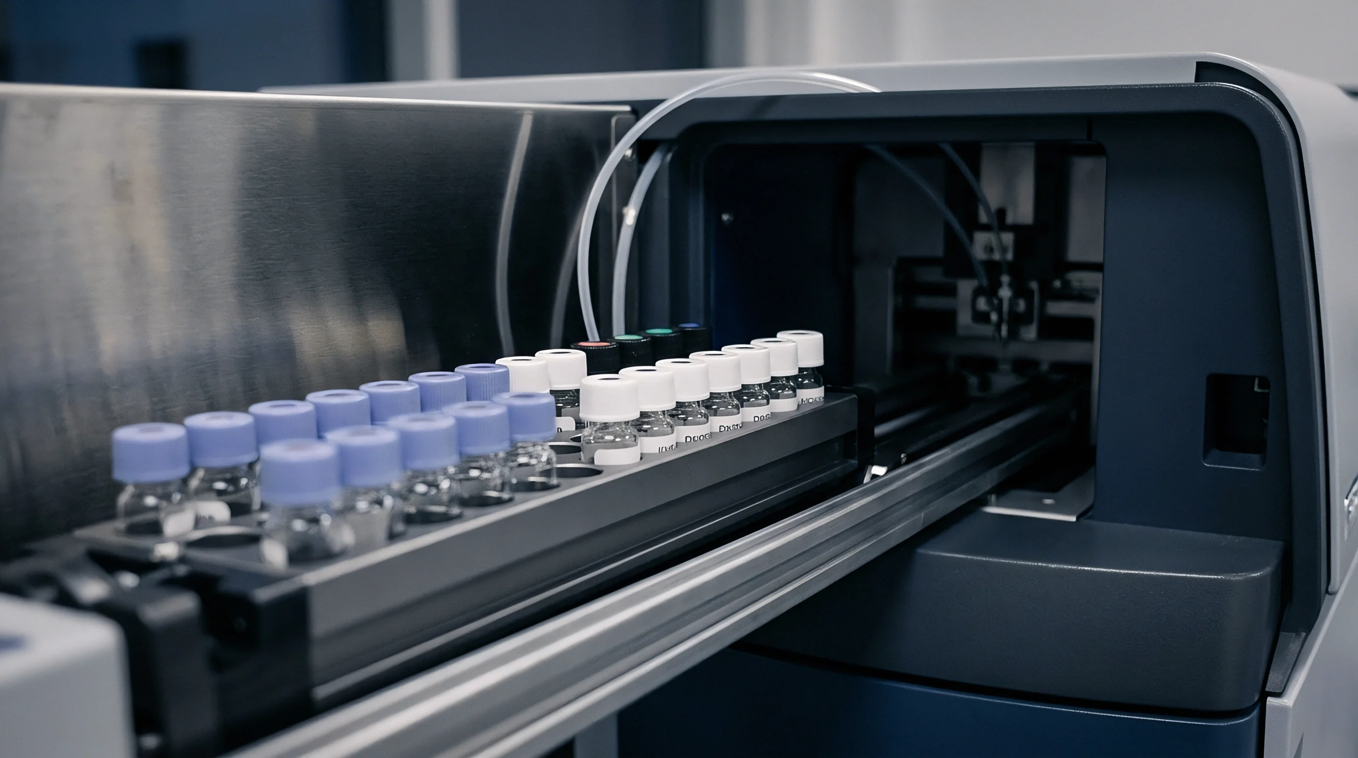
Verifying cavity texturing requires precise metrology protocols performed prior to tool signoff. Traditional stylus profilometry, while effective for flat machined surfaces, struggles inside small cavity radii and deep textures. Micro-stylus tips with radii of two to ten micrometers can scratch delicate chemical textures or fail to reach the bottom of narrow micro-valleys, underestimating total peak-to-valley height (Rz).
Non-contact optical metrology represents the industry standard for texture validation under ISO 21920 and ISO 4287 standards. White-light chromatic confocal sensors and focus variation microscopy capture full three-dimensional surface topographies non-destructively. These systems measure areal surface parameters defined by ISO 25178, providing comprehensive data beyond single-line profile metrics:
Sa = frac1A iintA |z(x,y)| , dx , dy
The areal average height (Sa), core void volume (Vv), and developed interfacial area ratio (Sdr) serve as critical input variables for predictive thermal resistance models. The developed area ratio (Sdr) measures the additional surface area provided by the texture relative to a flat plane. A smooth surface carries an Sdr of zero percent, while a deep chemical texture can exhibit an Sdr between forty and ninety percent.
Higher Sdr values increase ultimate metal contact area once high packing pressure forces polymer into micro-asperities, altering high-pressure thermal conductance.
Quality inspection standards mandate verifying texture metrics across multiple spatial locations per cavity. Standard protocol requires taking five measurement spots per cavity insert: one central measurement and four peripheral measurements near gate locations and fill extremities. In multi-cavity tooling, all cavities must meet specified Sa and Sz tolerances within a tight band of plus or minus seven percent of nominal values before approving the steel for first shots.
Process Window Optimization to Absorbing Etch Variance
When tool steel rework is financially unfeasible or would exceed delivery timelines, injection molding setters adjust processing parameters to mitigate the thermal impact of texture depth variations. Scientific molding methodology relies on decoupled process control to establish a robust process window capable of absorbing thermal contact resistance disparities.
The steps below outline the procedure for recalibrating mold processing windows when multi-cavity texture variations exist:
- Mount high-speed cavity pressure transducers flush behind textured surface zones in both the deepest-etched and shallowest-etched cavities.
- Perform a viscosity curve study to select an injection velocity operating on the flat plateau of the shear viscosity curve, minimizing fill pattern sensitivity to melt temperature variations.
- Conduct a gate seal study specifically tracking part weight separately for deep-etched and shallow-etched cavities across incremental holding time steps.
- Set the master process holding time to match the gate seal time of the deepest-etched cavity, preventing under-packing in high-thermal-resistance cavities.
- Adjust coolant flow rates within individual cooling zones to establish a lower mold temperature behind shallow-etched cavities, balancing localized heat extraction rates.
- Apply incremental holding pressure adjustments to locate the processing window center where all cavities fall within DIN 16742 TG4 tolerance bands simultaneously.
- Record real-time peak cavity pressure readings and thermal decay rates into the press quality control dossier to track shift-to-shift thermal drift.
Process adjustments carry physical limits. Increasing holding pressure forces plastic further into deep textures, reducing thermal contact resistance, but elevates part ejection forces. Higher ejection forces risk pin push-through, stress whitening, or mechanical scoring on textured vertical side walls.
The allowable draft angle must scale with texture depth: a general rule of thumb mandates adding one degree of draft per five micrometers of texture depth exceeding twenty micrometers. When draft angles remain restricted by part design, thermal modeling provides the sole path to balance processing parameters without causing mechanical damage upon ejection.
The procurement contract must specify that multi-cavity steel signoff depends on dimensional conformance across all cavities under a single unified process window, rather than individual cavity optimization.

Appraisal
Commercial Amortization of High Precision Etched Tooling
Precision multi-cavity tooling represents a major capital expenditure. A hardened sixteen-cavity H13 mold for automotive interior components frequently commands tooling investments between one hundred fifty thousand and three hundred thousand dollars. The chemical texturing phase itself accounts for five to ten percent of total tool cost, but improper etching management can ruin the entire cavity block investment, requiring expensive EDM sinking, welding, or insert replacement.
Tooling amortization calculations must account for scrap rates induced by thermal contact resistance variations across high-cavitation production runs. In high-volume manufacturing, piece price rests heavily on cycle time and material usage efficiency. A tool operating with uncorrected cavity-to-cavity thermal imbalance incurs higher scrap rates, extended cycle times to ensure gate freeze across all cavities, and elevated sorting costs during quality assurance checks.
| Commercial Factor | Conventional Etch Sourcing (Unmodeled) | Predictive Thermal Modeling Approach | Variance / Financial Impact |
|---|---|---|---|
| Initial Tooling & Texturing Cost | $185,000 | $202,000 | +$17,000 (Initial Capital) |
| Etch Inspection & Profilometry Audit | $1,500 | $6,500 | +$5,000 (Upfront Verification) |
| Tool Qualification & Trial Cycles | 4 Tool Trials (T1 to T4) | 2 Tool Trials (T1 to T2) | -$12,000 (Trial Savings) |
| Average Production Cycle Time | 26.5 seconds | 23.2 seconds | -3.3 seconds (-12.4%) |
| Scrap Rate (Dimensional / Gloss Rejects) | 4.2 % | 0.6 % | -3.6 % (Scrap Reduction) |
| Annual Operating Cost (500k parts/yr) | $645,000 | $572,000 | -$73,000 (Operational Gain) |
| Net Amortized Cost per Good Part (Yr 1) | $1.66 / unit | $1.55 / unit | -$0.11 / unit Net Savings |
Investing in predictive thermal resistance modeling prior to cutting steel increases initial engineering and inspection costs by seventeen thousand dollars. The commercial ROI materializes rapidly during serial production. By matching cavity heat extraction rates through predictive modeling and controlled etching depth standards, the production cycle time drops by three point three seconds per shot, while part scrap drops from four point two percent to zero point six percent.
Tooling costs rise. Operational gains recover the investment.
Savings accumulate over the operational lifespan of the mold. Across a production run of five hundred thousand units, the predictive thermal modeling approach yields a net savings of eleven cents per part, fully amortizing the initial modeling and metrology expenditure within six months of serial manufacturing.
Contractual Risk Allocation in Multi Cavity Tool Procurement
Procurement agreements for multi-cavity injection molds must assign clear technical and financial responsibilities for texture-induced dimensional failures. Standard supplier contracts often isolate chemical texturing as an aesthetic sub-contracted service, exempting texturing vendors from part dimensional compliance under DIN 16742 standards.
Buyers must protect their capital by incorporating explicit thermal performance clauses into purchase orders. The RFQ documentation must mandate that cavity texturing vendors provide certified non-contact profilometry reports confirming texture depth variance across all cavities remains within plus or minus five percent of nominal target specifications prior to tool assembly.
Tooling signoff requires proof that all cavities meet dimensional tolerances under one static machine setting.
Buyers should establish clear contractual requirements when ordering multi-cavity textured tooling:
- Certified Profilometry Dossier mandating full ISO 25178 optical surface measurements for every cavity insert before texturing signoff.
- Thermal Resistance Boundary Validation requiring the mold maker to demonstrate FEA thermal boundary matching during the tool design phase.
- Single-Process Window Signoff Clause stipulating that T1 sample acceptance depends on achieving specified tolerance grades across all cavities simultaneously under a single processing parameter sheet.
- Etch Depth Variance Remedies establishing that cavity inserts exceeding specified depth tolerance bands must be remanufactured at the supplier’s expense.
- Cavity Interchangeability Mandate requiring spare cavity inserts to match original thermal conductance parameters within three percent to allow direct drop-in replacement without process recalibration.
When a multi-cavity tool produces non-conforming dimensions due to unequal thermal extraction rates, financial liability rests with the toolmaker unless purchase contracts explicitly decouple texturing aesthetics from dimensional geometry. Integrating predictive thermal resistance modeling into the initial tooling design phase bridges the gap between surface finish specifications and physical dimensional tolerances, securing commercial investment across high-volume injection molding programs.
The contract line defining cavity interchangeability forces suppliers to hold surface micro-geometry to physical thermal standards rather than visual sample chips. Toolmakers who master predictive thermal modeling deliver molds that achieve immediate dimensional signoff across all cavities, bypassing weeks of empirical press-side troubleshooting and costly tool re-works.