Micro Injection Molding Tooling Tolerances and Alignment Systems
Sub-micron micro molding tooling requires preloaded rolling alignment, rigid pocket seating, and tight thermal regulation to hold sub-five-micrometer part tolerances.

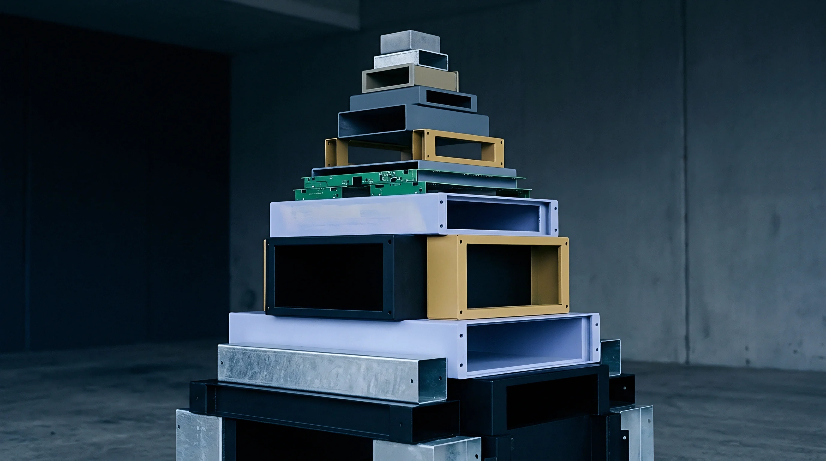
Datum
While machine platens distribute clamping force across large steel surfaces, micro-injection molding requires positional alignment within less than two micrometers. Milligram shot weights and sub-fifty-micrometer features turn standard mechanical clearances into unacceptable alignment errors. When part volumes fall below zero point one cubic centimeters, standard mold base tolerances swallow the part geometry entirely.
Holding predictable cavity registration requires an unbroken chain of reference surfaces running from the machine platens to the individual cavity insert walls.
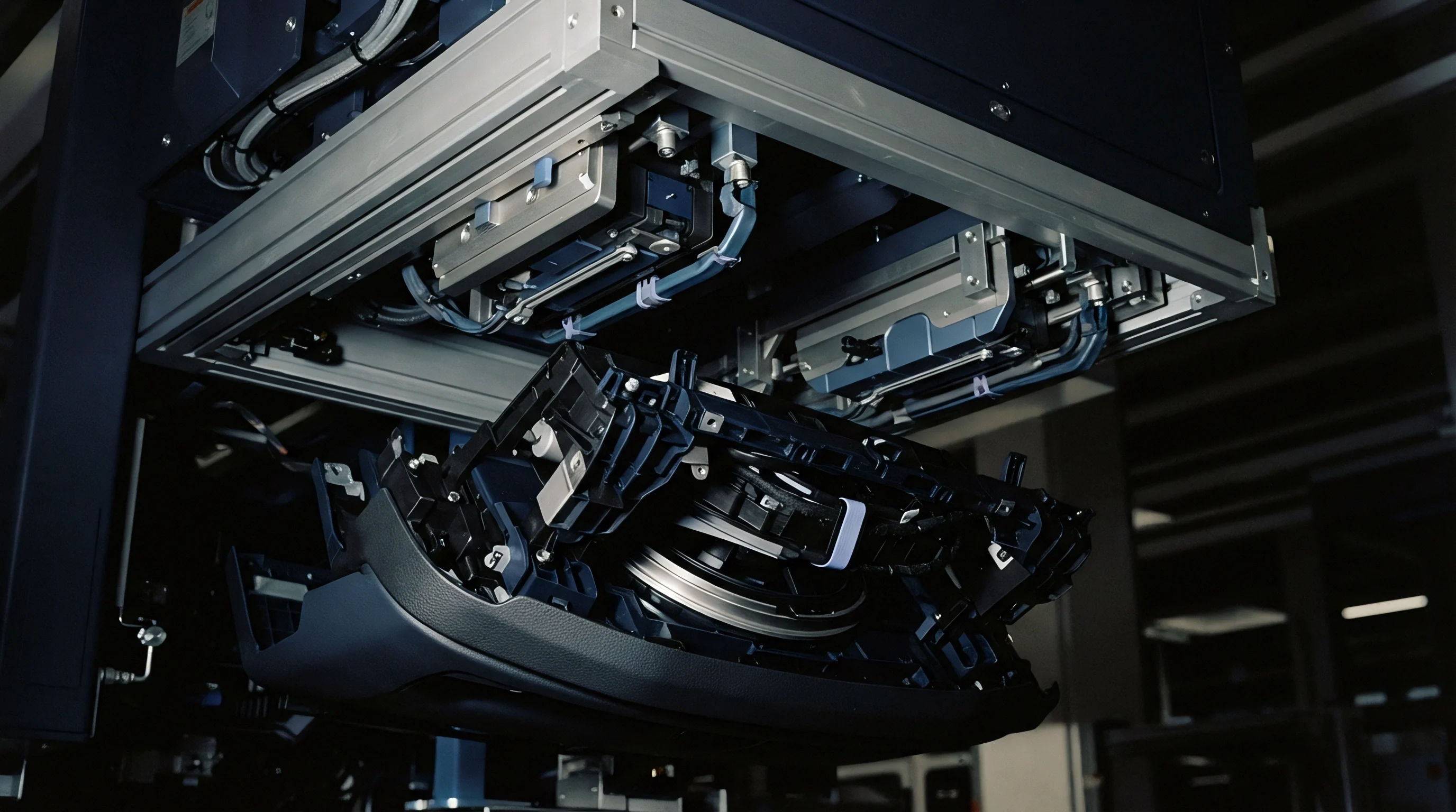
Reference Planes across Mold Plates
Micro-scale cavity positioning relies on a precise geometrical chain from the locating ring through to the pockets. Standard mold bases rely on a single central locating ring matched to the platen bore, but in sub-gram molding that single interface cannot guarantee rotational or planar alignment across the parting line. Precision tool designs instead put hardened, ground reference faces directly on the outer perimeter of the cavity plates.
These external datums establish primary, secondary, and tertiary reference planes, taking up mechanical play between the stationary and moving mold halves.
Flatness and parallelism across these plate datums require surface grinding to within zero point five micrometers per hundred millimeters of plate length, as sub-micron errors accumulate rapidly under thermal expansion. When clamping force compresses the plate stack, surface irregularities transfer directly into cavity distortion. Machining mold plates from stress-relieved steel alloys like AISI 420 or tool steel grade 1.2083 prevents internal stresses from relaxing during thermal cycling and distorting these reference planes.

Pocket Precision and Insert Seating
Electrical discharge machining can cut cavity recess walls to clearance limits under three micrometers. Machining cavities directly into full-size mold plates introduces manufacturing risk and limits thermal management, so high-precision tools use modular cavity inserts fitted into wire-EDM pockets within standard cavity plates. These pocket side walls require draft-free vertical surfaces cut on high-frequency wire EDM machines under temperature-controlled dielectric fluid loops.
Seating micro-inserts into plate pockets requires precise transition or light interference fits. Ground pocket floors must hold perpendicularity to the side walls within one micrometer over fifty millimeters. A dirt particle or resin flake measuring just five micrometers on a pocket floor will tilt an insert enough to misalign micro-core pins and cause wall thickness variations across tiny features.
| Alignment Interface | Standard Mold Base Play (µm) | Micro Tooling Target (µm) | Machining Process |
|---|---|---|---|
| Locating Ring to Platen Bore | 25.0 to 50.0 | 2.0 to 5.0 | Precision Cylindrical Grinding |
| Mold Plate Guide Pin Clearance | 12.0 to 20.0 | 0.5 to 1.5 | Preloaded Ball Bearing Cages |
| Pocket to Cavity Insert Wall Fit | 10.0 to 15.0 | 1.0 to 2.0 | Multi-Pass Wire EDM |
| Insert Seating Floor Perpendicularity | 5.0 to 10.0 | 0.5 to 1.0 | Optical Surface Grinding |
Holding micro-cavity positional variation under two micrometers demands precision grinding of pocket floors and rigid insert positioning.
Modular pocket designs allow worn cavity geometry to be replaced locally without scrapping expensive support plates. The fit between the insert and pocket wall transfers injection clamping loads directly into the main plate structure. Any gap behind the insert allows elastic deflection under high injection pressure, opening parting lines, creating flash, and accelerating wear on delicate core pins.
Referencing primary locating features directly to the cavity pocket edge eliminates cumulative stack-up errors across intermediate mold plates.

Guide
Standard leader pins in conventional mold bases allow ten to twenty-five micrometers of lateral play, which can ruin micro-features before the mold plates even close. Micro-injection tools require secondary and tertiary alignment systems that engage before male core pins enter female cavity pockets. These mechanisms must run cleanly without heavy grease lubrication, which threatens to contaminate micro-cavities and clog micro-vents.
Preloaded Ball Bearing Cages and Bushings
Rolling contact elements eliminate radial play during final closure. Ball bearing guide cages use precision bearing balls held under negative clearance against hardened steel guide pins and ground ceramic or steel bushings. Initial preloads between two and five micrometers eliminate mechanical slop as the guide pins enter mating bushings.
Provided they are kept clean, preloaded ball cages maintain alignment accuracy over millions of high-speed strokes.
Dry lubrication techniques, such as Diamond-Like Carbon or Titanium Nitride coatings, allow grease-free pin operation. Cleanroom molding of medical components like bio-resorbable surgical clips or micro-fluidic diagnostic chips excludes traditional hydrocarbon lubricants. Coated leader pins reduce friction, prevent galling, and preserve smooth motion during micro-ejection sequences.

Parting Line Alignment via Taper Interlocks
Flat and round centering blocks engage before cores enter the cavity block, with tertiary alignment taking place directly at the parting line through precision taper interlocks. These interlocks use ground matching tapers with surface roughness below Ra zero point zero five micrometers. Mounted on the cavity plate perimeter or integrated into individual insert edges, taper interlocks lock the mold halves together over the final half-millimeter of stroke.
Mechanical interlocks absorb lateral thrust generated by asymmetric plastic flow fronts in multi-cavity tools. As melt flows into micro-cavities through sub-fifty-micrometer gates, uneven filling exerts sideways pressure on core pins. Tapered locks convert these lateral forces into compressive loads across hardened steel surfaces, preventing cavity misregistration.
Verification of precision alignment during tool assembly follows a clear, structured shop-floor procedure:
- Clean all mold plates and cavity pocket surfaces using ultrasonic solvent baths to remove residual machining debris and oils.
- Measure plate flatness and parallelism across five reference points using a coordinate measuring machine equipped with an optical touch probe.
- Install preloaded ball bearing guide bushings into the primary support plates, verifying interference fit using dial indicators with zero point one micrometer resolution.
- Mount cavity inserts into wire-EDM pockets, applying torque-controlled tightening sequences to clamp bolts to prevent plate distortion.
- Apply optical bluing compound to taper interlock surfaces and perform slow manual mold closure on a bench press to inspect contact area symmetry.
- Measure final parting line registration across all cavities using an optical measuring microscope before mounting the tool into the press.
Guided ejector plate sets prevent tilt during the ejection stroke. When zero point three millimeter ejector pins drift out of axis by as little as two micrometers, they flex, gall against cavity walls, and snap. Mounting guided ejector plates on linear ball bushings maintains axial stroke integrity.
Uncorrected lateral clearance between mold halves accelerates core pin shearing, causes severe micro-parting line flash, and damages delicate cavity features during high-speed cycling.


Expansion
Steel dimensions shift whenever thermal energy enters the mold block from heating channels, hot runner nozzles, or molten polymer. Thermal expansion is among the largest sources of dimensional instability in micro-tooling. Standard tool steels expand by roughly eleven to twelve micrometers per meter for every degree Celsius temperature rise.
In micro-molding, even a minor temperature differential across the mold face produces dimensional shifts that exceed specified part tolerances.
Thermal Drift Mechanics in Steel Plates
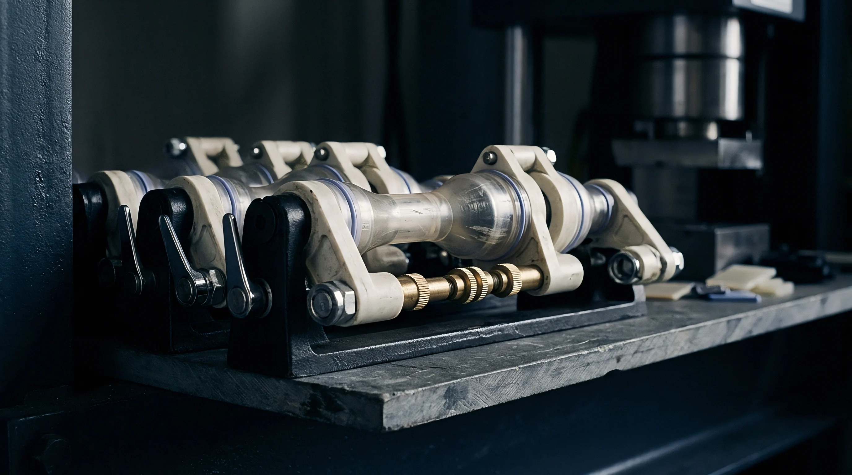
A five-degree Celsius shift across a two-hundred-millimeter block displaces outer features by more than one micrometer. When the stationary mold half runs at eighty degrees Celsius to maintain resin flow while the moving half runs at forty degrees Celsius for rapid cooling, the plates expand unevenly. Pockets on the stationary side expand outward while those on the moving side remain compact, pulling cold-side core pins out of alignment with hot-side cavity pockets.
Thermal expansion requires careful matching of material expansion coefficients across mold components. Pairing stainless cavity plates with tungsten carbide inserts generates internal stress during warmup. Carbide has a thermal expansion coefficient near five point five micrometers per meter per degree ~ about half that of stainless steel.
Without engineered expansion gaps or floating insert mounts, thermal cycling leads to insert binding, pocket cracking, or loss of baseline alignment.
| Material Grade | Expansion Coefficient (10⁻⁶/K) | Thermal Conductivity (W/m·K) | Hardness Range (HRC) |
|---|---|---|---|
| AISI H13 (1.2344) Tool Steel | 11.8 | 24.5 | 48 to 54 |
| AISI 420 (1.2083) Stainless Steel | 10.5 | 19.0 | 50 to 54 |
| Tungsten Carbide (10% Co) | 5.5 | 80.0 | 72 to 78 |
| Copper Beryllium (Ampcoloy 940) | 17.0 | 208.0 | 28 to 30 (HRC equivalent) |

Isothermal Fluid Loops and Temperature Stability
Pressurized fluid circulation units can hold delivery temperatures within one-tenth of a degree Celsius. Micro-injection molds require dedicated, high-flow temperature control units capable of pumping fluid through small conformal channels. Deep micro-drilled passages or laser-sintered conformal cooling networks deliver coolant within millimeters of cavity walls to maintain stable geometry.
Hot runner systems in micro-molding present tough thermal isolation challenges. Direct valve gates and hot tip nozzles operate between two hundred and four hundred degrees Celsius, driving heat from the manifold into the colder cavity plates around them. Ceramic isolation washers, air gaps, and active water-jacket cooling plates surround the hot runner assembly to block heat conduction and keep pocket temperatures uniform across all tool stations.
Maintaining temperature variations under zero point two degrees Celsius across mold plates prevents thermal drift from exceeding sub-micron alignment thresholds.
Processors using uncalibrated heating loops experience changing cavity positions throughout shift warm-up periods. First shots pulled from a cold tool display incorrect wall thicknesses compared to parts molded after four hours of steady-state operation.


Deflection
Injection pressures approaching three thousand bar generate immense internal force against slender core pins and thin cavity walls. High injection velocities ~ up to one thousand millimeters per second ~ force molten polymer into micro-channels within fractions of a second. These hydraulic surges act on micro-tool geometries like mechanical hammers.
Without sufficient structural rigidity, micro-cores bend, plates separate, and cavity dimensions distort under dynamic load.

What Thermal Drift Invalidates Sub-Micron Insert Alignment?
Temperature gradients over two degrees Celsius across the core plate produce asymmetrical growth that exceeds physical guide tolerances. When thermal expansion forces overcome guide pin clearance, leader pins bind in their bushings. This binding causes uneven mold closure, introduces bending moments into core pins, and shifts cavity locations relative to ejector pins during cycling.
Slender core pins are vulnerable to flow-induced bending. For example, a micro-core pin forming a fluid port inside a medical valve housing might measure zero point one five millimeters in diameter and project zero point seven five millimeters into the cavity ~ an aspect ratio of five to one. If gate location or filling symmetry varies slightly during injection, resin fills from one side first, creating a pressure differential across the pin that generates a severe bending moment.
Core pin bending calculations demonstrate this vulnerability clearly. Modeling the core pin as a cantilever beam subjected to a uniform lateral pressure differential yields peak deflection at the free tip:
Deflection = (q L⁴) / (8 E I)
Where q represents the lateral line load, L represents pin length, E represents the steel elastic modulus (210,000 MPa for tool steel), and I represents the area moment of inertia (I = pi d⁴ / 64). For a pin diameter (d) of 0.15 mm and length (L) of 0.75 mm under a lateral pressure differential of 100 bar (10 MPa), the calculation proceeds:
I = (3.14159 0.00000000050625) / 64 = 2.485 10⁻¹ groo. m⁴ (2.485 10⁻¹⁸ m⁴)
Line load q = Delta P d = 10 MPa 0.15 mm = 1.5 N/mm = 1500 N/m
Deflection = (1500 (0.00075)⁴) / (8 210,000,000,000 2.485 10⁻¹⁸) = 0.000000475 / 0.004175 = 0.000113 m = 113.7 µm
A calculated deflection of 113.7 micrometers destroys a component whose total wall thickness is only fifty micrometers. The core pin bends into the opposing cavity wall, shutting off flow, creating micro-flash on one side, and shearing the pin tip after a few cycles. Balanced multi-gating or dual flow channels equalize pressure around slender pins, reducing transverse deflection.
Core deflection under asymmetrical hydraulic flow fronts represents the primary structural cause of wall thickness failure in micro-tubing and micro-housings.

Parting Line Separation and Micro Flash Boundaries
Clamping units must withstand internal cavity pressure to keep plate separation under two micrometers. Micro-molding resins like Liquid Crystal Polymers, Polyoxymethylene, and Polyetheretherketone exhibit extremely low melt viscosity at processing temperatures, allowing them to penetrate parting line gaps as small as two to three micrometers and form razor-thin micro-flash.
Machine platen rigidity governs parting line integrity. Platen flex under full clamping load causes local separation along the center of the cavity plates, while tie-bar elongation, uneven clamping force, and thin support plates aggravate cavity breathing. Rigid tool design requires thick backing plates, hardened support pillars directly behind cavity pockets, and high-tonnage electric press clamping frames.
Hydraulic pressure spikes during injection must be cushioned by stable machine hydraulic loops or fast-acting servo-electric drives. Rapid pressure spikes trigger dynamic elastic deflection of mold plates before the machine clamp can react. The exact point where core pin vibration under high-velocity melt flow triggers fatigue failure remains difficult to model without real-time pressure transducers inside the micro-cavity.

Tolerance
Defining acceptable dimensional variations for components weighing under zero point one gram requires specialized international standards. Standard tolerancing frameworks like ISO 2768 fail on micro-molded geometries because their coarsest bands are larger than the parts themselves. Instead, plastic parts rely on dedicated standards like DIN 16742 or ISO 20457 to set realistic production expectations.

International Standards and Mold Capability Limits
DIN 16742 establishes dimensional groupings for precision plastic moldings, ranging from TG1 for extreme precision down to TG8 for general industrial parts. Micro-injection moldings almost exclusively require TG1 or TG2 performance.
| Nominal Dimension Range (mm) | TG1 Precision Tolerance (µm) | TG2 High Tolerance (µm) | TG3 Standard Tolerance (µm) |
|---|---|---|---|
| Up to 1.00 mm | ± 9.0 | ± 14.0 | ± 22.0 |
| 1.00 to 3.00 mm | ± 11.0 | ± 17.0 | ± 26.0 |
| 3.00 to 6.00 mm | ± 13.0 | ± 20.0 | ± 31.0 |
| 6.00 to 10.00 mm | ± 15.0 | ± 23.0 | ± 36.0 |
Achieving TG1 limits on features under three millimeters requires mold tool tolerances below three micrometers, alongside raw material shrinkage variation held strictly under zero point one percent. Fluctuations in resin viscosity, regrind content, barrel residence time, and shop humidity alter volumetric shrinkage across shifts, making shrinkage variability a primary obstacle to maintaining TG1.

Process Capability Indices for Micro Moldings
Calculating statistical capability indices for micrometer-scale features requires optical measurement devices with sub-micron repeatability. Conventional touch-probe coordinate measuring machines exert enough force to flex delicate plastic micro-features during contact. Non-contact optical metrology ~ such as white light interferometry, laser confocal microscopy, and micro-focus X-ray computed tomography ~ replaces physical contact.
A process capability index (Cpk) target of one point three three requires that the total process spread (six sigma) consumes no more than seventy-five percent of the engineering tolerance band. For a micro-gear tooth thickness specified at zero point two zero zero millimeters with a tolerance of plus or minus five micrometers, the total allowable zone is ten micrometers, meaning the six-sigma distribution must fall within seven point five micrometers across the entire lot.
Quality verification for micro-tooling sign-off requires evaluating several core capability criteria before approving volume production:
- Tooling dimension verification requires non-contact optical inspection reporting sub-micron cavity feature conformity across all cavitation streams.
- Shot weight stability demands a coefficient of variation below zero point five percent calculated across fifty consecutive shots per cavity.
- Parting line flash assessment obligates high-magnification optical inspection confirming zero flash exceeding three micrometers in length.
- Thermal recovery testing requires demonstrating steady-state dimensional control within twenty minutes of press startup following interruptions.
- Ejection force monitoring mandates recording steady ejector pin force profiles to confirm zero binding or galling across automated cycles.
Quality documentation for medical micro-parts demands full traceability between raw material melt flow index and final part dimension reports. Incorporating DIN 16742 Table 2 TG1 specifications into supply agreements places responsibility on the molder to maintain tight oil temperature and cushion control during long production runs.

Replacement
High shot counts erode tiny cavity details through polymer abrasion and corrosive off-gassing. Glass-filled polymers, highly filled liquid crystal polymers, and ceramic-filled resins act like liquid sandpaper against sharp steel edges. A gate corner radius ground to five micrometers can round off to twenty micrometers after fifty thousand cycles, altering filling patterns and creating micro-burrs.
Modular Insert Strategies and Wear Dynamics
Designing split cavity blocks allows damaged micro-features to be replaced without scrapping the main mold plate. Sub-micron tool longevity depends heavily on substrate selection: while standard tool steels like H13 offer toughness, they lack wear resistance against abrasive resins. Premium powder-metallurgy stainless steels like CPM S90V, Elmax, or solid tungsten carbide extend cavity life by five to ten times compared to conventional steels.
Tungsten carbide micro-inserts resist abrasive wear and maintain crisp sub-micron edges past one million shots. Processing carbide requires specialized methods, including micro-wire EDM in ultra-fine oil dielectric fluid and diamond grinding. Because carbide is brittle, inserts require solid backing steel inside pockets to prevent fracture under dynamic hydraulic pressure spikes.

Tooling Amortization and Unit Cost Sensitivity
Initial capital expenditure for sub-micron tooling is amortized across production volumes to determine unit economics. Precision micro-molds carry high up-front costs due to extensive machining hours, optical-grade polishing, and micro-metrology verification. Evaluating an eighty thousand dollar tool that yields two million parts against a forty thousand dollar tool that fails after two hundred thousand parts illustrates the commercial trade-off.
Amortization calculations for a two-cavity medical micro-housing tool demonstrate these unit cost dynamics:
Assume Option A utilizes standard hardened stainless steel cavity inserts costing $45,000 with a expected wear lifespan of 250,000 shots. Total yield equals 500,000 parts. Amortized tool cost per part equals $45,000 / 500,000 = $0.090 per unit.
Option B utilizes powder-metallurgy CPM S90V inserts with preloaded ball alignment cages costing $75,000, delivering a wear lifespan of 1,250,000 shots. Total yield equals 2,500,000 parts. Amortized tool cost per part equals $75,000 / 2,500,000 = $0.030 per unit.
Option C utilizes solid tungsten carbide inserts with sub-micron taper locks costing $110,000, delivering a wear lifespan of 3,000,000 shots. Total yield equals 6,000,000 parts. Amortized tool cost per part equals $110,000 / 6,000,000 = $0.018 per unit.
Investing in powder-metallurgy steel or carbide inserts lowers unit tooling amortization by up to eighty percent over multi-million part production runs.
Provisioning spare inserts during the initial build protects against unscheduled downtime. Ordering two spare sets of critical cavity inserts during the original wire-EDM setup adds roughly fifteen to twenty percent to initial tooling costs while cutting future downtime costs in half. Swapping a worn insert set takes hours, whereas remachining micro-inserts from scratch during a production crisis causes weeks of delay.
Tool ownership contracts should specify wear limits and replacement responsibilities. Setting clear thresholds ~ such as a maximum allowable gate erosion of ten micrometers or maximum flash length of five micrometers ~ establishes unambiguous criteria for refurbishing inserts. Rigorous maintenance tracking paired with rapid modular insert swaps keeps micro-injection lines running within sub-micron tolerances over long production lifetimes.