Fundamental Principles of Micro Injection Mould Tooling Setup
Micro injection mould tooling setup requires sub-micron bolster alignment, vacuum venting, balanced thermal profiles, and strict clamp tonnage limits.


Platen
Micro injection mould tooling operates in a physical domain where machine kinematics, thermal expansion, and mechanical compliance directly conflict with micro-scale feature definitions. The primary mechanical interface begins at the press platens. In conventional moulding, platen deflection within 0.05 mm across the tie-bar span produces negligible part variation.
In micro-moulding, where part masses drop below 10 milligrams and wall sections reach 50 micrometers, a 0.02 mm platen deflection vents cavity air paths unevenly, inducing localized flash or non-fill.
Tool setup requires measuring the static parallelism of the stationary and moving platens using dial test indicators mounted to a rigid bridge fixture. Parallelism across the clamped area must register below 0.005 mm per 100 mm of span. Dynamic alignment under full clamp load presents a separate verification challenge.
When the clamping unit toggles lock or hydraulic cylinders pressurize, platens bow slightly convex, concentrating contact stresses at the tool center while relaxing clamp force at the periphery.
Platen deflection above 0.008 mm across the bolster face vents parting line gas unevenly, triggering asymmetrical flash in thin-wall micro cavities.
Centering rings on micro-tool bolsters require precision ground diameters toleranced to ISO 286-2 grade h6, mating with platen register bores finished to H7. A standard commercial clearance of 0.03 mm allows the tool assembly to settle eccentrically under its own weight before clamp force locks the bolsters. This mechanical shift shears delicate shut-offs and misaligns sub-millimeter sprue bush orifices with machine injection nozzles.
Tool setup protocols demand coaxial dial indicator sweeps around the sprue bush internal diameter relative to the machine barrel axis, holding concentricity within 0.003 mm total indicated runout.
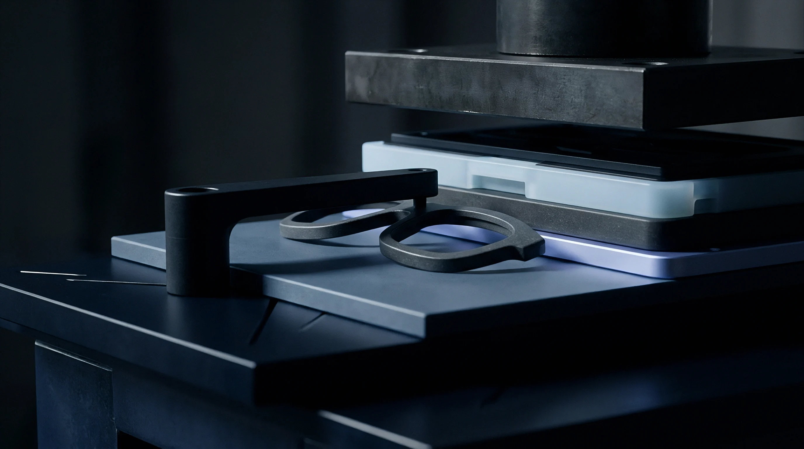
Mechanical Clamping Force Distribution
Excessive clamp force crushes microscopic venting structures and accelerates parting line fatigue. Micro moulds rely on parting line vents measuring between 0.001 mm and 0.004 mm deep, depending on polymer melt viscosity. Excessive clamping tonnage collapses these microscopic channels, sealing air inside cavities and generating severe diesel burns.
Setting clamp tonnage follows projected area calculations, applying an operational ceiling of 1.15 times the calculated force rather than maximizing press capacity.
| Alignment Parameter | Target Specification | Verification Method | Tolerance Grade |
|---|---|---|---|
| Platen Parallelism | < 0.005 mm / 100 mm | Bridge-Mounted Dial Indicator Sweep | ISO 1101 Narrow |
| Locating Ring Register | +0.000 / -0.008 mm | Internal Micrometer / Bore Gauge | ISO 286-2 H6/h6 |
| Sprue Concentricity | < 0.003 mm TIR | Axial Dial Indicator Runout Test | DIN 16742 Group 1 |
| Dynamic Bolster Tilt | < 0.004 mm Under Load | Four-Point Inductive Probe Array | ISO 10791-1 |
Bolster bolting torques directly alter internal insert alignment. Uneven tightening sequences across clamping flange bolts distort sub-plate stacks, shifting micro cavities out of square. Technicians employ cross-pattern torque wrench sequences in three escalating increments, checking bolster face planarity between steps with a granite-referenced electronic level.
Precision ground spacers and hardened support pillars beneath cavity inserts eliminate unsupported spans, preventing plate bending moments when the injection piston strikes peak pressure.
Toolmakers often state that any modern all-electric press holds alignment without dial testing.


Register
Inter-plate registration dictates whether split cavity geometries match across parting planes. Standard guide pins and bushings allow radial play between 0.010 mm and 0.025 mm, which exceeds permissible part tolerances on micro components. Precision micro mould tooling segregates the rough guidance of outer plates from the fine alignment of core and cavity inserts.
Outer bolster sets use standard components solely to protect projecting ejector pins during tool assembly.
Fine registration relies on precision interlock systems fitted directly to internal insert pockets. Tapered interlocks provide high centering stiffness under clean conditions. Thermal gradients between moving and stationary halves induce differential expansion across taper faces, causing galling or asymmetrical clearances.
Flat taper locks installed on all four insert quadrants permit thermal growth away from the geometric tool center while locking planar position along orthogonal axes within 0.001 mm.

Guiding Element Clearances
Sub-micron guidance assemblies incorporate preloaded ball bearing cages or precision ground prism blocks coated with diamond-like carbon. Operating clearances in these sub-assemblies drop to zero, maintained under deliberate light interference. Insert mounting pockets in backer plates require CNC jig grinding after heat treatment, holding position tolerances below 0.002 mm relative to reference datums.
If pocket sidewalls taper or deviate from 90 degrees, torquing insert retention screws twists core faces, throwing side-action shut-offs out of alignment.
- Interlock Prism Blocks ground to matched sets within 0.001 mm establish absolute transverse alignment before core faces touch shut-off planes.
- Preloaded Ball Bushings eliminate radial clearance in internal plate stacks while maintaining low sliding friction during mould open and close sequences.
- Direct Insert Locators pressed into jig-ground pockets bypass stack-up errors accumulating across multi-plate bolster sets.
- Side-Action Gib Guides fitted with hardened beryllium copper wear plates maintain sub-micron alignment across high-speed slide travels.
Parting line shut-off angles on micro cores rarely exceed seven degrees due to component footprint limits. A steep shut-off angle paired with loose guide pins causes contact scuffing, rounding sharp edges that define flash-free perimeters. Optical inspection of parting land perimeters using high-magnification white light interferometry verifies edge radii remain below 0.005 mm prior to production release.
A supplier often claims that mechanical play vanishes once clamp pressure compresses the taper locks.


Manifold
Thermal management within micro-moulding melt delivery systems presents severe rheological contradictions. Melt volumes within runners frequently exceed actual cavity shot volumes by an order of magnitude. If a runner system contains 500 cubic millimeters of material while an eight-cavity cluster consumes 12 cubic millimeters, resin experiences prolonged thermal residence times, triggering molecular weight loss through chain scission.
Micro tool setup prioritizes hot runner tip profiles, sub-millimeter nozzle geometries, and precise temperature boundary control.
Direct hot runner gating into micro cavities requires externally heated nozzle tips with tight thermal profiles. Heat sink effects from adjacent chilled cavity plates induce rapid nozzle freeze-off if thermal separation falls short. Ceramic isolation rings and titanium insulating barriers isolate heated runner blocks from cold tool steel, limiting heat loss to under 50 Watts per gate position.
Tip temperature profiles require calibration using calibrated micro-thermocouples embedded within 0.5 mm of the gate land, checking that steady-state temperatures vary by less than 1.5 degrees Celsius across all drops.

Flow Path Dimensions and Volume Ratios
Cold runner designs demand sub-runner branches proportioned down to hair-like dimensions. Secondary cold runners often feature trapezoidal or circular profiles under 0.8 mm in diameter, terminating in sub-gates measuring 0.15 mm to 0.30 mm. Setting up these tools requires balancing fill pressure demands against shear rates.
High injection velocities force polymers through tiny gate orifices at shear rates surpassing 100,000 reciprocal seconds, causing viscous dissipation and local melt degradation.
| Delivery System Type | Runner-to-Part Ratio | Permissible Temp Drift | Max Shear Rate |
|---|---|---|---|
| Micro Hot Runner Tip | 1.5:1 to 3:1 | +/- 1.0 °C | 75,000 s⁻¹ |
| Valve-Gated Manifold | 2:1 to 5:1 | +/- 1.5 °C | 50,000 s⁻¹ |
| Balanced Cold Sub-Runner | 8:1 to 20:1 | +/- 0.5 °C (Plate) | 120,000 s⁻¹ |
| Direct Sprue Micro Gate | 0.8:1 to 1.5:1 | +/- 2.0 °C (Nozzle) | 90,000 s⁻¹ |
Valve gate actuation in micro tools requires pneumatic or servo-electric drive units that seat gate pins without impacting cavity steel. A pin advancing with standard hydraulic force easily deforms a 0.20 mm gate orifice, mushrooming the steel and generating perpetual flash. Setter protocols mandate setting pin shut-off travel via micrometer stroke adjusters, establishing zero-clearance land engagement without metal-to-metal seating impact.
Under DIN 16742 Group 1 criteria, thermal variations exceeding two degrees across drops generate volumetric cavity imbalances that breach tolerance boundaries.
Melt residence time calculations determine production viability. Consider a medical micro component moulded in polyetheretherketone with a shot volume of 0.008 cubic centimeters running on a standard 14 mm screw and barrel setup. The barrel inventory holds 6.5 cubic centimeters of melt.
Resin remains at 380 degrees Celsius across more than 800 cycles, causing material degradation before reaching the gate. Stable setup mandates specialized micro injection units utilizing 5 mm or 8 mm plunging pistons fed by separate plasticizing screws, reducing melt inventory to under 0.3 cubic centimeters.
Residual stress patterns from uneven manifold temperatures manifest as dimensional warpage post-demoulding, rendering micro gears and optical lenses non-functional.

Temper
Variations in cavity steel temperature alter micro feature replication efficiency and cycle stability. Because micro parts have tiny thermal masses, polymer melt crystallizes or vitrifies within milliseconds of contacting cavity walls. Standard water cooling channels spaced 15 mm away from cavity surfaces fail to provide dynamic thermal response.
Setup procedures incorporate high-frequency thermal monitoring and dynamic variothermal heating cycles to balance filling speed against part ejection stiffness.
Variothermal tooling utilizes rapid heating via induction coils, ceramic resistance cartridges, or alternating pressurized steam circuits to elevate cavity surfaces above polymer glass transition or melting temperatures prior to injection. The melt fills intricate sub-micron surface topographies without forming a frozen skin layer. Once the cavity fills and packs, chilled water circuits drop tool temperatures below part ejection thresholds.
Setting up these cycles requires fine-tuning heating and cooling phase switches within millisecond intervals.
Cooling Channel Distribution
Cavity inserts built via selective laser melting integrate conformal cooling passages running within 0.8 mm of feature surfaces. These internal cooling channels feature complex internal geometries that maximize turbulent flow at modest fluid delivery rates. Coolant flow setup demands verifying Reynolds numbers above 4,000 across every circuit using calibrated digital flow meters.
If scale deposits or particulate matter choke a micro conformal line, local steel temperatures surge, introducing cycle-to-cycle shrink variations exceeding the total part tolerance band.
A three-degree coolant shift alters polyoxymethylene micro-gear tooth profiles beyond acceptable limits.
Thermal expansion calculations verify that cavity inserts remain stress-free inside retaining pockets across operating temperature sweeps. An insert heated to 160 degrees Celsius expands against a bolster held at 40 degrees Celsius. Without calculated expansion gaps, compressive stresses buckle insert faces or freeze moving ejector guide pins.
Assume an insert footprint measuring 50 mm by 50 mm made from DIN 1.2343 tool steel with a coefficient of thermal expansion equal to 11.5 multiplied by ten to the negative sixth power per Kelvin. A temperature delta of 80 Kelvin expands each insert axis by 0.046 mm. Machinists grind pocket expansion clearances to 0.050 mm, relying on center-anchoring keys to locate the insert datum while steel expands freely into designated clearances.
Thermocouple placement governs closed-loop feedback stability during automated production runs. Placing sensing probes too deep into base plates buffers the registered signal, hiding rapid temperature spikes. Technicians install spring-loaded mineral-insulated thermocouples within 1.0 mm of cavity shut-off lands, directly coupling thermal data to press process controllers.
The moulder assumes continuous variothermal cycling functions indefinitely without checking for internal micro-cracking across diffusion-bonded cooling layers.


Eject
Demoulding micro injection moulded components introduces severe structural risks. Because part walls are thin, ejection forces applied over small contact areas generate massive compressive and shear stresses. An ejector pin measuring 0.3 mm in diameter applying a force of merely 15 Newtons exerts a compressive stress of over 210 megapascals on the moulding, exceeding the yield strength of engineering polymers at ejection temperatures.
Tool setup requires careful balancing of mechanical stripper mechanisms, micro pin arrays, and pneumatic assistance.
Stripper plate mechanisms provide continuous peripheral contact, distributing demoulding forces evenly across outside edges. Stripper plate setup requires checking clearance fits around stationary cores. Radial clearances between stripper bores and core pins must stay below 0.002 mm.
A clearance of 0.006 mm allows low-viscosity polymers to pack into the annular gap under high pressure, forming an annular ring flash that binds the mechanism and rips the part upon plate actuation.

Micro Ejection Kinematics
Individual micro ejector pins require precise guide lengths within hardened plates to prevent buckling under load. Pins below 0.5 mm diameter utilize stepped construction: a rigid 2.0 mm shank steps down to the working micro-diameter over the final 3.0 mm of working travel. Setting ejector forward stroke lengths demands sub-micron digital micrometer adjustments.
Over-stroking drives pin faces past cavity surfaces, creating witness steps on parts or colliding with automated end-of-arm handling tooling.
- Ejector Pin Protrusion aligned within +0.000 / -0.002 mm relative to cavity floors prevents mechanical interlocking during lateral shrinkage.
- Stripper Guide Bushings ground with zero-clearance ball cages maintain planar parallelism, preventing core cocking during ejection strokes.
- Pneumatic Poppet Valves introducing micro-filtered air bursts break surface vacuum before mechanical pins advance against part walls.
- Differential Return Systems equipped with early return mechanisms shield fragile pins from advancing slide units during mould reset cycles.
Adhesion forces between polished steel surfaces and moulding resins often dominate the initial demoulding phase. Vacuum forces generate resisting loads that buckle delicate micro-ribs. Technicians inspect cavity discharge ports to confirm that air assistance lines provide dry, oil-free air at 6 bar pressure before pins initiate motion.
The air burst separates part surfaces from cavity walls, cutting mechanical pin stress by half.
Part handling mechanisms interface directly with ejector plate motion. Micro parts lack sufficient mass to drop reliably via gravity, often clinging to mould steel through electrostatic attraction or grease film adhesion. Automated vacuum pick-and-place end effectors require positional synchronisation with ejector pins, holding parts during the demoulding stroke and confirming component release via optical transmission sensors before closing the press.
Uneven mechanical pin drag across multi-cavity layouts tilts micro frames, cracking microscopic gear shafts during ejection.
Balance
Achieving simultaneous, identical cavity filling across multi-cavity micro moulds represents a challenging fluid dynamics problem. In standard tooling, runner volume variations average out under sustained packing pressures. In micro-moulding, where cavity fill times drop below 0.1 seconds, subtle variations in runner wall surface roughness, corner radii, or gate lands unbalance the fill pattern, causing some cavities to flash while adjacent cavities show short shots.
Artificially balanced runner layouts, where varying runner lengths rely on differing cross sections to balance flow resistance, fail when processing polymers with shear-rate-dependent viscosity profiles. True physical symmetry remains mandatory. Every flow branch must present identical lengths, channel cross sections, directional turns, and surface polish grades from the sprue axis to individual gate entries.
Setup verification demands short-shot progression studies, cutting shot sizes to 20, 40, 60, and 80 percent of total volume to evaluate fill balance across all positions.

Can Cavity Pressure Sensors Correct Unbalanced Micro Tool Geometries?
Direct cavity instrumentation provides real-time verification of cavity filling dynamics. Piezoelectric pressure sensors with pin diameters down to 0.5 mm install directly beneath micro ejector pins or behind cavity walls, measuring in-cavity pressures throughout the fill-pack-hold cycle. While sensor feedback lets setters tune machine transfer positions accurately, process parameter shifts cannot physically compensate for geometric tooling imbalances or asymmetrical thermal distributions across runner plates.
| Cavity Position | Peak Pressure (bar) | Fill Time (ms) | Part Weight (mg) |
|---|---|---|---|
| Cavity 1 | 642 | 42 | 8.42 |
| Cavity 2 | 638 | 43 | 8.40 |
| Cavity 3 | 645 | 41 | 8.43 |
| Cavity 4 | 612 | 49 | 8.21 |
| Cavity 5 | 640 | 42 | 8.41 |
| Cavity 6 | 644 | 42 | 8.42 |
| Cavity 7 | 639 | 43 | 8.40 |
| Cavity 8 | 641 | 42 | 8.41 |
Analysis of data in the table identifies Cavity 4 as an outlier, exhibiting a pressure drop of 30 bar, longer fill durations, and reduced component mass. In micro tooling setups, this defect indicates gate land dimensional error, sub-runner debris, or localized cooling circuit obstruction. A 0.005 mm variation in gate width alters filling resistance significantly, shifting part dimensions beyond narrow drawing limits.
Gate freeze studies verify that the packing phase seals every cavity gate simultaneously. If one gate freezes 0.2 seconds earlier than its neighbors, that cavity loses packing pressure early, producing sink marks, voids, and uncontrolled volumetric shrinkage. Technicians run parts across escalating hold-time increments, weighing cavities on ultra-precision micro-balances sensitive to 0.001 milligrams until part mass plateaus.
The tooling vendor attributes filling variances to polymer lot inconsistencies rather than runner machining errors.

Vent
Venting micro moulds demands exact micro-machining control. When polymer melt fills cavity volumes within tens of milliseconds, trapped air cannot escape through conventional clearance spaces. The compression of trapped air raises local temperatures past the thermal degradation limits of polymers, scorching parts via the diesel effect and oxidizing tool steel faces.
Micro mould venting requires evacuation channels that vent air freely without permitting melt ingress.
Vent land depths depend on polymer surface tension and viscosity under high shear rates. Low-viscosity polyamides require vent channels ground to depths between 0.0010 mm and 0.0015 mm. High-viscosity polymers like polycarbonate or polysulfone tolerate vents up to 0.0035 mm deep without flashing.
These vent depths extend across a primary land of 0.50 mm before expanding into atmospheric relief channels measuring 0.05 mm deep. Setup checks use surface profilometry to confirm vent geometry, verifying that grinding passes left flat land floors free from burrs.
- Profilometer Measurement logs primary vent land depths at eight parting line locations to confirm conformity to polymer flash limits.
- Solvent Ultrasonic Cleaning removes residual anti-corrosion oils and EDM carbon films that obstruct sub-micron air paths.
- Vacuum Seal Verification tests the integrity of periphery O-rings using an automated helium decay leak detector.
- Pressure Decay Testing confirms that cavity evacuation draws down to 50 millibar within 150 milliseconds of vacuum valve actuation.
Active vacuum evacuation systems replace passive parting line vents in challenging micro-moulding applications. The tool perimeter incorporates an elastomer vacuum gasket that seals before the primary tool faces engage. A vacuum pump evacuates cavity air down to 20 millibar prior to melt injection.
Vacuum evacuation widens the usable process window, cuts required injection pressures, and prevents knit-line weakness across sub-millimeter pins.
Sintered porous metal inserts provide alternative venting solutions for blind micro-cavity pockets. Steel inserts featuring pore distributions between 0.002 mm and 0.005 mm vent air through core pins where parting line relief cannot reach. Ultrasonic cleaning protocols remain essential for porous inserts, as condensed polymer volatiles and waxes rapidly clog fine pores during sustained operations.
Parting line venting configurations in micro tooling leave the mold engineer pondering how nano-scale surface coatings influence air molecule slip during microsecond evacuation cycles.

Wear
Abrasive wear and surface fatigue rapidly degrade micro tool geometries. Reinforced engineering polymers containing short glass fibers, carbon nanotubes, or ceramic fillers accelerate gate and shut-off erosion. A glass fiber measuring 0.010 mm in diameter behaves like an abrasive chisel within a gate orifice measuring 0.15 mm across.
Once erosion rounds gate edges or widens shut-off lands by 0.002 mm, parts develop unacceptable flash, driving scrap rates up.
Base tool steel selection sets baseline wear resistance. Micro cavity inserts utilize through-hardened powder metallurgical steels such as DIN 1.3344 or DIN 1.2379, heat-treated to hardness levels between 60 and 64 Rockwell C. These steels provide uniform carbide distribution, preventing carbide grain pull-out during micro-EDM or diamond fly-cutting processes. Standard pre-hardened steels lack the yield strength needed to resist microscopic peening across cyclic shut-off impacts.

Physical Vapor Deposition Coatings
Thin-film coatings enhance wear resistance and reduce demoulding friction coefficients. Physical vapor deposition processes apply titanium aluminum nitride, chromium nitride, or tetrahedral amorphous carbon coatings at thicknesses between 0.0008 mm and 0.0020 mm. Coating deposition temperatures must remain below tool steel tempering points to avoid softening inserts.
Uniform coating adhesion requires substrate surface finishes polished to an arithmetic roughness average below 0.02 micrometers prior to chamber loading.
Cavity degradation tracking requires high-resolution optical metrology at specified cycle intervals. White light interferometers scan shut-off edges every 25,000 cycles, tracking edge radius decay against baseline measurements. If edge rounding exceeds 0.006 mm, the tool returns to the toolroom for insert re-grinding and re-coating.
The contract manufacturer routinely accounts for tool steel wear by raising machine clamp tonnage, damaging internal shut-off lands permanently.