Anisotropic Fiber Alignment Variance in Multi-Axis Machining Nests for Glass Reinforced Polyamide Assemblies
Anisotropic fiber alignment dictates local part compliance, requiring cavity-matched machining nests with controlled clamp forces to prevent post-release distortion.


Gate
Injection moulded glass reinforced polyamide carries a structured arrangement of short glass fibers frozen into place during cavity filling. Across a nominal 3.0 mm wall section of PA66-GF30, the shear flow against the chilled tool steel aligns fibers parallel to the injection vector within the outer 0.4 mm skin shells. The central core cools under extensional flow, allowing fibers to settle perpendicular to the melt stream or disperse in a semi-random planar spread.
This physical gradient creates a modulus mismatch across the section thickness. Longitudinal tensile modulus parallel to flow reaches 8,800 to 11,000 MPa, while transverse modulus across flow drops to 4,800 to 6,200 MPa. When multi-axis machining nests register on these surfaces to cut seal lands or bore bearing journals, this directional stiffness variation translates into uncompensated elastic compliance under cutting loads.
Standard CNC nests locate parts against datum faces under the assumption of uniform bulk elasticity. Toolroom fixtures built with rigid mechanical toggles or fixed-pressure hydraulic clamps impose point forces that distort anisotropic plastic housings before the spindle touches the stock. A locating button pressing against a skin-dominated flow zone deflects by 0.012 mm under 250 N of normal force, whereas that same clamp force applied across a transverse weld line induces 0.038 mm of localized compliance.
Unclamping after the machining cycle releases these stored elastic strains, warping machined faces out of true position.
A locating nest designed for unreinforced resin distorts glass filled parts before the spindle engages the stock.
Multi-cavity tooling compounds the problem across the machining pallet. Tool designers balance runner lengths to fill cavities at equal rates, yet flow vectors inside four or eight distinct cavities rotate relative to global machine axes. Cavity 1 presents a longitudinal fiber skin to the primary locating nest pad, while Cavity 4 presents a transverse core zone to the identical pad location.
Machining nests that lack per-cavity datum compensation record significant tool deflection and feature-to-datum true position failure. The toolmaker manages this dispersion by tying machining datums to stable melt flow paths rather than aesthetic part perimeters.
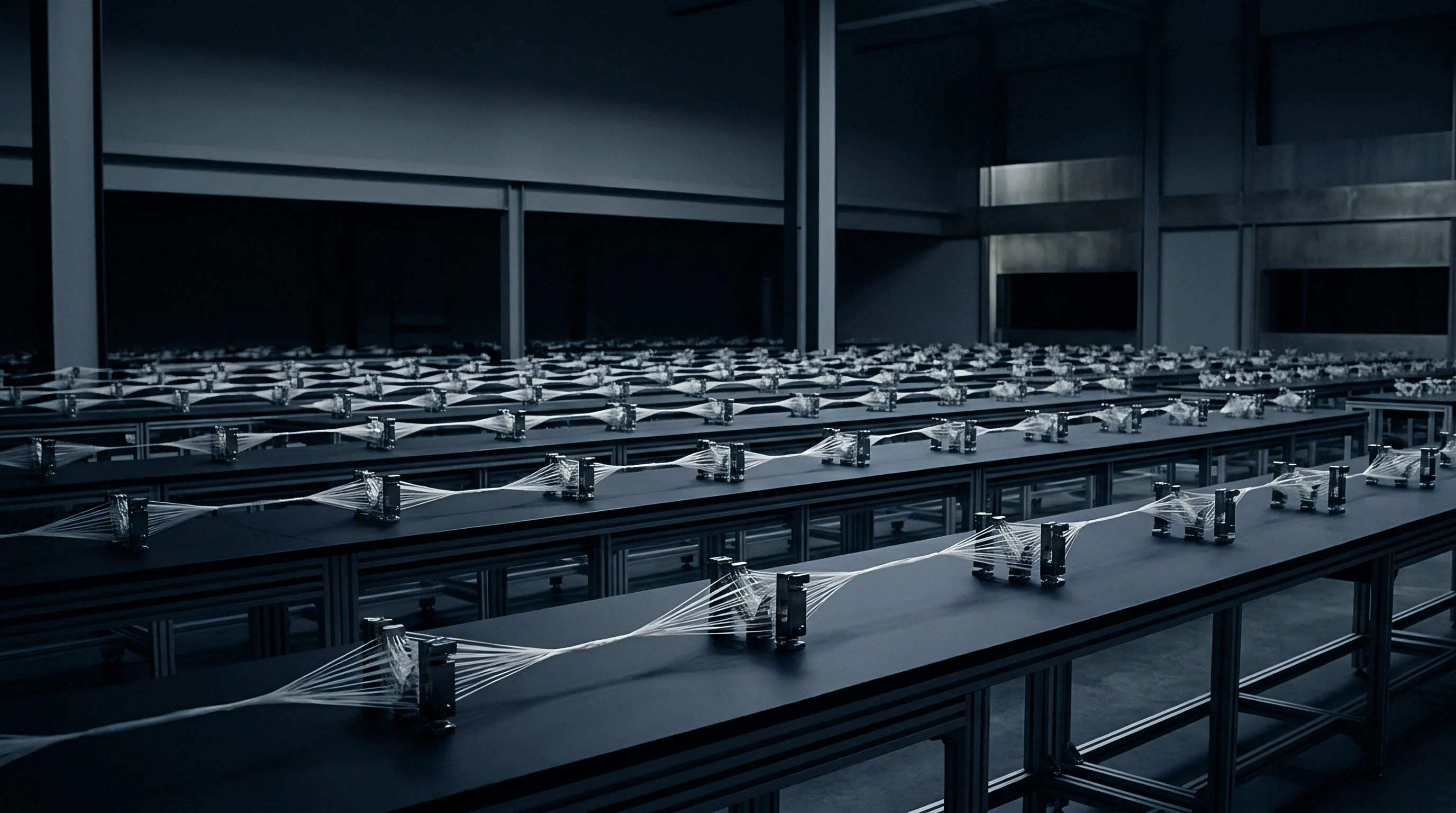
Melt Flow Mechanics across Cavity Layouts
Runner systems govern the spatial orientation of reinforcement fibers as the polymer enters each impression. Edge gates produce diverging radial flow that sweeps fibers into concentric shells around the gate entry point. Fan gates establish broad, parallel streamlines across flat webs, reducing transverse angular dispersion.
Submarine and cashew gates create intense shear fields that shear fiber bundles, lowering average fiber length from 250 micrometers in the virgin granule to 120 micrometers directly adjacent to the gate entry. A shorter fiber length degrades local composite modulus, altering compliance at adjacent machining locators.
Symmetrical cold runner layouts yield varying fiber orientations when parting lines force asymmetrical gate locations across mirrored components. In an eight-cavity tool producing four left-hand and four right-hand electrical connector housings, gate placement often flips 180 degrees between paired impressions to preserve runner balance. A single multi-axis machining nest holding eight parts simultaneously subjects Cavities 1 through 4 to down-milling against longitudinal fibers, while Cavities 5 through 8 experience down-milling against transverse fibers.
The resulting differential cutting forces deflect parts unevenly inside their individual nest pockets.
Fiber orientation tensors capture this internal distribution across three spatial coordinates. At the outer skin, the diagonal tensor component along the flow path reaches values between 0.75 and 0.85, indicating near-total parallel alignment. In the central third of the wall section, this component drops to 0.35, while the transverse component climbs to 0.55.
Machining operations that remove this stiff outer skin expose the low-modulus core, causing the component to curl toward the unmachined face as residual moulding stresses equilibrate across the remaining cross-section.
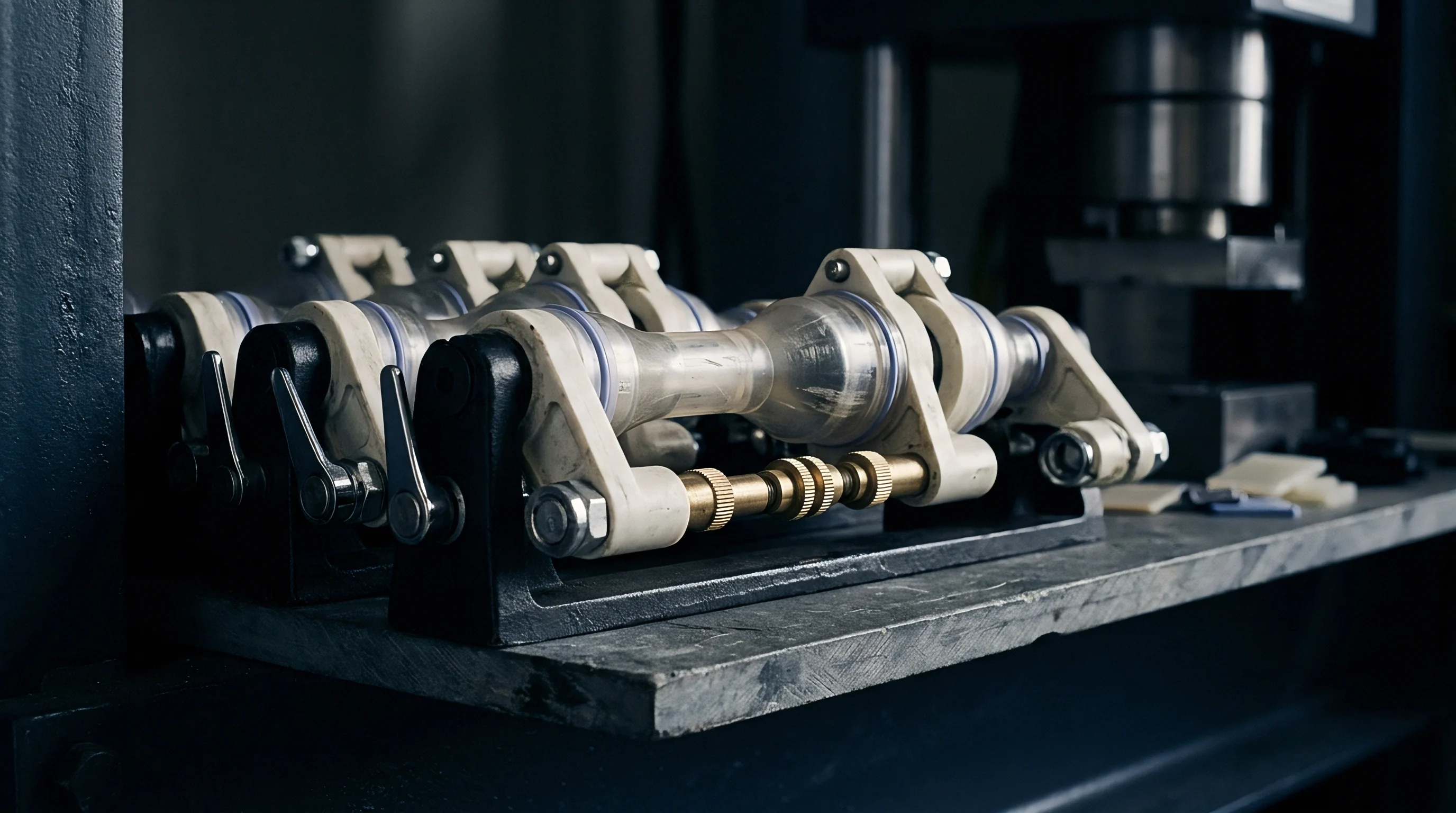
Can Toolmakers Neutralize Fiber Orientation Drift?
Toolrooms attempt to eliminate fiber variance by running mold filling simulations during runner sizing. Filling simulation predictions match injection pressure drops within five percent, yet predicted fiber orientation tensors diverge from measured micro-computed tomography data near internal ribs and core pins. Diverging melt fronts recombine behind coring pins to create passive weld lines where fibers align purely parallel to the seam rather than traversing it.
Clamping a machining nest pad onto an unseen weld line introduces a local stiffness trough that simulation routines regularly overestimate by 30 to 45 percent.
Mold cooling design directly alters skin thickness and local anisotropic ratios. Rapid cooling freezes a thicker shear skin, expanding the high-modulus shell at the expense of core relaxation. Running cavity temperatures at 80 degrees Celsius yields a 0.3 mm skin, whereas running oil-heated tools at 130 degrees Celsius permits polymer relaxation, thinning the skin to 0.15 mm and increasing overall crystallinity.
Tool setters manipulate mold surface temperatures to stabilize dimensions, unwittingly altering the mechanical rigidity of the datum pads gripped by downstream CNC fixtures.
Varying holding pressure profiles shifts the volumetric packing gradient from gate to flow end. High holding pressures compress additional material into the gate region, intensifying fiber packing densities to 33 percent by weight locally, while dead-end features retain only 28 percent reinforcement. This mechanical density difference alters the local indentation hardness of locating surfaces.
Machining nests relying on edge contact experience variable brinelling under clamp load across production shifts.
| Layer Depth From Surface (mm) | Flow Direction Tensor A11 | Transverse Tensor A22 | Tensile Modulus Parallel (MPa) | Tensile Modulus Normal (MPa) | Linear Shrinkage Rate Parallel (Percent) |
|---|---|---|---|---|---|
| 0.00 to 0.35 (Skin) | 0.82 | 0.14 | 10,400 | 5,100 | 0.25 |
| 0.35 to 0.80 (Shear) | 0.68 | 0.26 | 8,900 | 5,800 | 0.35 |
| 0.80 to 1.50 (Core) | 0.38 | 0.54 | 5,600 | 8,200 | 0.75 |
| 1.50 to 2.20 (Shear) | 0.66 | 0.27 | 8,700 | 5,900 | 0.38 |
| 2.20 to 3.00 (Skin) | 0.80 | 0.15 | 10,100 | 5,200 | 0.28 |
Downstream machining programs that assume a uniform elasticity across the workpiece scrap high-value parts when milling cuts push components off their datums. Process engineers counter this risk by mapping cavity-specific fiber layouts directly to clamping sequences on the mill. The question remains whether mold designers can deliberately position gates to place predictable, isotropic fiber zones beneath critical machining datums without compromising structural flow lengths across thin external walls.


Vise
Mechanical workholding fixtures transfer spindle loads into machine tables through static datums and dynamic clamps. When clamping glass filled polyamide, nests interact with a material that possesses anisotropic compliance, non-linear creep, and low surface hardness compared to light metals. Applying standard steel vise jaws to an unreinforced area generates an elastic deflection calculation based on isotropic Young’s modulus.
In PA66-GF30, clamping across the transverse fiber direction yields double the displacement observed along the longitudinal flow axis under identical screw torque.
Multi-axis nesting blocks rely on 3-2-1 locating schemes utilizing spherical locating buttons, diamond pins, and resting pads. Spherical buttons concentrate clamping forces onto microscopic contact areas. A 6 mm diameter spherical locating pin bearing a 400 N seating load generates localized contact stresses exceeding 85 MPa.
This stress level breaches the compressive yield limit of dry-as-moulded PA66 at 23 degrees Celsius, initiating permanent indentation into the moulded datum pad. The workpiece settles lower into the nest, introducing vertical datum shift into multi-axis rotary toolpaths.
Surface compliance variations degrade part stability during rapid 5-axis indexing. When an auxiliary rotary axis accelerates at 1.5 g, inertial forces from an overhung assembly transfer through the nest clamps. If the nest secures a low-stiffness transverse fiber zone, the part shifts elastically inside the nest during positional moves.
Tool cutting edges engage material out of projected space, introducing scalloping and surface steps across continuous O-ring grooves.

Clamping Topologies under Directional Stiffness
Distributing clamping force over conforming nest pads prevents surface indentation while arresting multi-axis machining movement. Elastomeric nest interfaces fabricated from 90 Shore A polyurethane distribute holding forces across complex outer contours, damping spindle vibrations. Elastomers exhibit hysteresis that complicates absolute datum positioning.
Toolrooms replace compliant elastomeric pads with vacuum chuck nests contoured via high-speed milling to match the shrinkage profile of the specific moulding cavity.
Vacuum fixtures eliminate concentrated mechanical point loads by drawing workpieces against form-fit cavities under negative atmospheric pressure. A vacuum seal drawn across a 150 square centimeter surface generates approximately 1,200 N of uniform holding force at 80 kPa vacuum level. This uniform pressure prevents localized shell buckling in thin-walled housings.
Vacuum nests cannot counter axial lifting forces produced by aggressive positive-rake spiral end mills, requiring auxiliary top clamps placed directly opposite structural support bosses.
Pneumatic toggle clamps maintain set cylinder pressures yet permit dynamic variations when shop air line pressures fluctuate across working shifts. Hydraulic workholding units coupled with proportional pressure reducing valves provide repeatable holding forces within two percent across all pallet positions. Placing load cells beneath nest datum pins verifies that clamping force levels remain beneath the critical shear threshold of glass filled skin layers.
- Primary Datum Seating applies low-pressure pneumatic engagement between 30 and 50 kPa, registering the component against three primary nest locators without introducing elastic bending across thin-walled sections.
- Cavity Identification Interlock reads the molded data matrix code on the assembly, verifying that the part matches the designated nest pocket and calling cavity-specific tool offset tables inside the CNC control.
- Secondary Edge Alignment actuates opposed non-influencing slide clamps to locate the secondary datum rail, maintaining contact force below 150 N to prevent buckling across transverse fiber fields.
- Final Hydraulic Clamping applies proportional downward pressure onto reinforced structural ribs, bringing vertical holding force to 800 N directly over solid nest support columns.
- Vacuum Seal Verification samples differential pressure across the nest base to confirm complete perimeter contact, aborting the spindle cycle if vacuum draw drops below 75 kPa.
Machinists who omit continuous force monitoring risk crushing the softer polymer matrix, creating microcracks around glass fibers that degrade fatigue life under field loads.

Shear
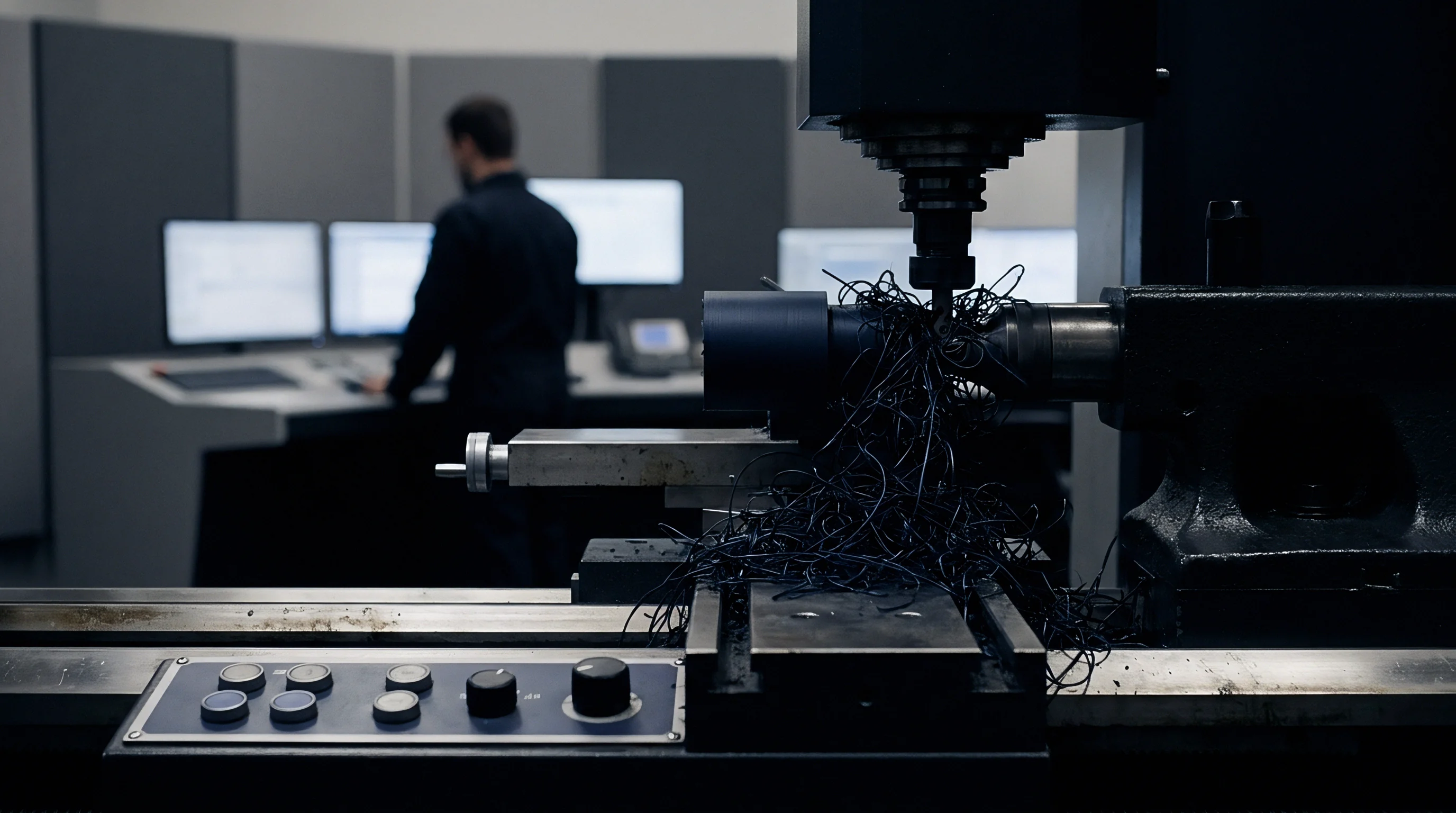
Machining operations on glass reinforced polyamide involve chip formation mechanics distinct from metal cutting. The tool edge does not continuously shear a homogeneous lattice. Instead, the cutting edge encounters high-hardness abrasive glass filaments embedded in a ductile, viscoelastic nylon matrix.
When cutting parallel to fiber alignment, the wedge of the tool lifts fibers out of the matrix through mode I peeling before buckling them in flexure. This peeling mechanism creates smooth sub-surface cavities and yields minimal tool wear. Cutting transverse to fiber alignment forces the cutting edge to fracture glass filaments via pure transverse shear, generating extreme abrasive wear and high cutting force spikes.
A diamond-coated solid carbide end mill rotating at 12,000 RPM experiences cutting force fluctuations of up to 240 percent within a single rotation as the tool tooth transitions from a longitudinal skin layer to a transverse core layer. This fluctuating load excites machine spindle harmonics and deflects slender tooling. Machining nests that hold the component along its perimeter must absorb these cyclic cutting forces without resonant vibration.
If the nest’s natural frequency aligns with the tooth pass frequency, the workpiece vibrates, degrading finished bore circularity beyond standard automotive limits.
Abrasive glass fibers oriented perpendicular to the cut induce three times the cutter edge wear of aligned fibers.
Chip formation mechanics alter finished surface roughness. When cutting transverse to fibers, fractured glass ends protrude from the machined surface, producing Ra values exceeding 3.2 micrometers regardless of feed per tooth. Cutting along the fiber direction allows the matrix to wipe across buried glass ends, yielding surface finishes below 0.8 micrometers Ra. Post-machining inspections often flag this variation as tool wear or spindle bearing runout when it represents a shift in raw fiber orientation across the toolpath.
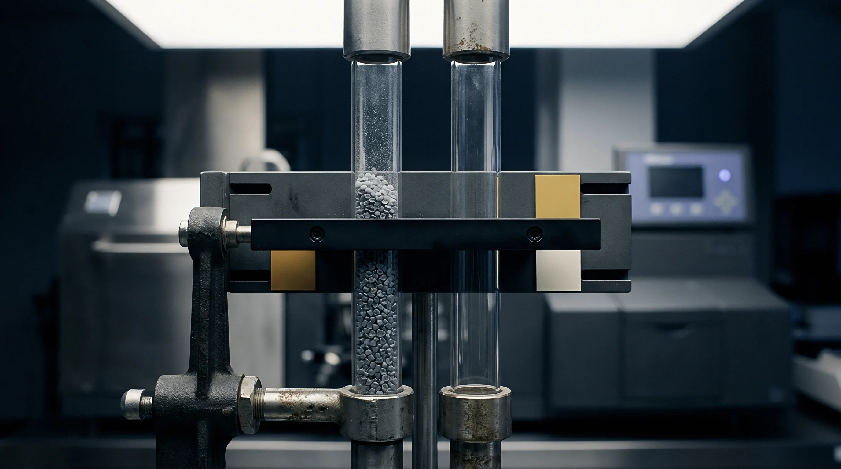
Tool Geometry and Micro-Fracture Mechanics
Tool wedge angles dictate the mode of fiber fracture during high-speed milling passes. Highly positive rake angles between 12 and 18 degrees slice cleanly through glass bundles, lowering normal cutting forces that push against the nest datums. Extremely sharp cutting edges wear rapidly due to the abrasive impact of E-glass fibers possessing a hardness of 6.5 on the Mohs scale.
Micro-chipping on razor-sharp carbide edges rounds the cutting radius from 5 micrometers to 25 micrometers within 200 parts, increasing passive thrust force by 180 percent.
Polycrystalline diamond (PCD) tools maintain an edge radius below 8 micrometers across extended machining runs. The diamond table resists glass abrasion, maintaining consistent cutting forces across 50,000 parts. Toolmakers specify single-crystal or ultra-fine grade PCD for finishing passes where bore tolerances must remain within ISO 286 grade IT7.
Coated carbide tooling with titanium silicon nitride (TiSiN) or physical vapor deposition diamond films provides an economical alternative for roughing operations where higher passive forces can be tolerated by stiff machining nests.
Helix angles alter the direction of cutting force vectors applied to the nesting fixture. High helix end mills (45 to 55 degrees) convert radial cutting resistance into axial drawing forces that pull the workpiece up out of the nest pocket. Machining thin-walled PA66-GF30 housings with high helix cutters lifts the part off its bottom datums, introducing depth errors on blind milling pockets.
Low helix tools (15 to 30 degrees) direct cutting forces down into the nest support pads, utilizing the structural rigidity of the machine table to arrest vibration.
| Cutter Material And Coating | Fiber Angle To Cutting Vector (Degrees) | Cutting Speed Vc (m/min) | Feed Per Tooth fz (mm) | Resultant Force Fxy (N) | Edge Flank Wear VB After 500m (mm) |
|---|---|---|---|---|---|
| Uncoated Carbide (K10/K20) | 0 (Parallel) | 250 | 0.08 | 45 | 0.065 |
| Uncoated Carbide (K10/K20) | 90 (Transverse) | 250 | 0.08 | 135 | 0.185 |
| TiSiN PVD Coated Carbide | 0 (Parallel) | 350 | 0.10 | 42 | 0.035 |
| TiSiN PVD Coated Carbide | 90 (Transverse) | 350 | 0.10 | 122 | 0.095 |
| Polycrystalline Diamond (PCD) | 0 (Parallel) | 600 | 0.12 | 28 | 0.008 |
| Polycrystalline Diamond (PCD) | 90 (Transverse) | 600 | 0.12 | 78 | 0.015 |
| Data gathered using a 10 mm diameter 2-flute end mill at 2.0 mm axial depth of cut and 3.0 mm radial width of cut under dry machining conditions. | |||||
Spindle speed choices must avoid resin softening temperatures. Glass reinforced polyamides maintain structural modulus up to the glass transition temperature of the matrix, which sits at 50 to 65 degrees Celsius for dry PA66. Exceeding this boundary through excessive cutting friction smears the nylon matrix over the fibers, forming tough burrs along part edges that defy automated deburring operations.

Coolant Delivery and Hygroscopic Expansion
Flooding the cutting zone with water-soluble coolant lowers tool temperatures and flushes abrasive glass sludge out of the machining nest pockets. Polyamide 66 absorbs atmospheric and liquid moisture through hydrogen bonding within its amorphous regions. Immersing bare, machined surfaces in water-miscible emulsions initiates dimensional swelling before quality engineers measure parts on a coordinate measuring machine (CMM).
A standard 30 percent glass filled polyamide component absorbs approximately 0.15 percent water by weight per day of immersion, swelling by 0.05 percent linearly. For a 120 mm wide bearing housing, this absorption alters bored centerlines by 0.06 mm within a forty-eight-hour quality hold. Flood coolant also enters micro-voids opened by fiber pulling, triggering sub-surface plasticization that softens the resin matrix and reduces localized thread-stripping strength on tapped fastener holes.
Dry machining utilizing vortex-tube cold air guns prevents moisture pickup while suppressing thermal degradation at the cutter edge. Chilled air delivered at minus 10 degrees Celsius cools the cutting interface, freezes the nylon chips into brittle fragments, and evacuates abrasive debris from nest datum surfaces. Machine builders configure enclosures with high-capacity dust extractors to capture hazardous airborne respirable glass fibers dislodged during dry milling.
Failure to evacuate glass particles from locating nests introduces random positioning errors across production runs. Loose glass fibers settle between part datums and nest resting pads, introducing variable datum elevation steps of 0.015 mm to 0.040 mm that destroy multi-axis profile tolerances.


Drift
Dimensional stability in glass filled polyamide parts changes over time through mold shrinkage, moisture equilibration, and thermal expansion. When parts transition from injection molding to multi-axis machining nests, these mechanisms alter workpiece geometry. Moulded PA66-GF30 parts shrink anisotropically during crystallization: shrinkage parallel to fiber alignment averages 0.2 to 0.4 percent, while shrinkage transverse to alignment ranges from 0.7 to 1.1 percent.
Nests built to nominal CAD models fail to support warped parts uniformly, causing locators to bridge across hollows or rock on high crowns.
The time interval between injection molding and secondary machining introduces dimensional variance across factory shifts. A component machined four hours post-molding retains residual thermal energy and remains at near-zero moisture content. That same batch machined seventy-two hours later has cooled to ambient room temperature and begun absorbing moisture from factory air, expanding its physical envelope.
In climates with uncontrolled ambient humidity, seasonal shifts from winter heating to summer humidity swing base part dimensions across a 0.20 mm band.
Post-molding shrinkage curves demand a mandatory dwell period before parts touch a multi-axis CNC nest.
Thermal expansion during the machining cycle compounds these base dimension shifts. Glass reinforced polyamide possesses a coefficient of thermal expansion (CTE) of approximately 25 to 35 ppm/K parallel to fiber alignment, escalating to 65 to 85 ppm/K in the transverse direction. Aluminum machining nests expand at 23 ppm/K, while steel nests expand at 12 ppm/K. A temperature swing of 10 degrees Celsius inside an unconditioned machine shop induces differential expansion between nest locators and plastic components, introducing binding or datum clearance play.

Accounting for Hygroscopic Expansion across Machining Cycles
Polyamides equilibrate with environmental humidity until reaching saturation. PA66-GF30 absorbs up to 2.5 percent moisture by weight at standard conditions of 23 degrees Celsius and 50 percent relative humidity, expanding linearly by 0.25 percent across its bulk geometry. If manufacturing lines machine parts in the dry-as-moulded condition, components swell past drawing tolerance limits once packaged and shipped into humid field environments.
Critical dimensions must be cut offset from nominal drawing targets to compensate for expected downstream hygroscopic growth.
Accelerated conditioning regimes stabilize parts prior to the nesting operation. Conditioning batches in climate chambers at 70 degrees Celsius and 62 percent relative humidity accelerates moisture uptake, achieving equilibrium in hours rather than months. Conditioned parts become softer and more ductile; the tensile modulus drops from 9,500 MPa down to 6,000 MPa, altering workholding compliance inside the machining nest.
Clamping pressures calibrated for dry parts crush conditioned components, requiring separate clamp recipes based on pre-machining conditioning status.
In-process coordinate measuring machine inspections must capture the hygroscopic history of the production lot. Measuring a freshly machined part at the machine bench yields a different numerical result than measuring that same part twenty-four hours later inside a temperature-controlled metrology lab. Quality plans must document specific dwell times and environmental parameters for inspection acceptance, standardizing the thermal and moisture state of the polymer lattice.

Does Cavity Ageing Compromise Fixture Repeatability?
Tool steel wear alters cavity dimensions over production life cycles. Abrasive glass fibers sliding under high injection pressures erode gates, runner transitions, and cavity walls. After 500,000 injection cycles, gate cross-sections enlarge, altering cavity filling velocity and shifting internal fiber orientation tensors.
Parts molded late in a tool’s lifespan exhibit lower shear orientation and higher transverse core thickness than initial T1 off-tool samples. Machining nests designed around first-article parts experience fit problems as the mold steel wears.
Tooling wear also degrades parting line seal integrity, generating flash along primary datum edges. Flash thicknesses of 0.05 mm lift parts off nest resting blocks, skewing 5-axis alignment planes. Automated edge-deburring operations or dedicated flash-clearing clearances built into the nest nesting pockets are essential to maintain stable datum seating throughout the lifecycle of the injection mold.
Process setters frequently compensate for tool wear by hiking injection packing pressures to suppress sink marks. This press-side adjustment packs more polymer into the core, shifting internal stress states and inducing unpredictable out-of-plane warp upon part ejection. An assembly that once rested flat in its CNC nest begins to rock across its diagonal datums, introducing angular misalignment that ruins precision machining features.
- Uncontrolled Part Resting creates variable datum positioning when parts rest on variable molding flash along parting lines.
- Premature Clamping Cycles introduce permanent creep deformation when components enter machining nests before complete crystallization.
- Inadequate Thermal Isolation transfers spindle motor heat into aluminum nest bodies, expanding locators past part drawing limits.
- Uncompensated Moisture Uptake causes precision bore diameters to shrink below nominal limits as the surrounding plastic wall swells inward over time.
- Unbalanced Tool Clamping bends thin structural webs against empty nest pockets lacking supporting hydraulic backup jacks.
Plant quality teams eliminate these baseline shifts by establishing strict staging protocols between the press and the mill. Skipping this dwell protocol guarantees high scrap rates at the final assembly line.

Gauge
Verifying dimensional compliance in multi-axis machined polyamide parts requires measurement systems that isolate part deformation from genuine machining error. Traditional tactile coordinate measuring machines (CMM) deploy touch-trigger probes that apply mechanical contact forces between 0.05 N and 0.15 N. On soft, anisotropic plastics, this contact force indents the surface by several micrometers, recording an incorrect coordinate point. Optical scanning systems and structured light metrology capture full-field surface profiles without mechanical contact, revealing complex free-state warpage patterns.
Geometric dimensioning and tolerancing (GD&T) schemes for glass reinforced plastics demand custom datum reference frames that reflect functional assembly constraints. Specifying free-state tolerances allows suppliers to report gross part warp without penalty, whereas restrained tolerances require inspection fixtures that simulate mating sub-assemblies. When drawing callouts mandate restrained inspection, metrology nests must replicate the clamping forces and datum contacts utilized during the CNC machining operation to ensure measurement repeatability.
Micro-computed tomography (micro-CT) provides non-destructive scanning of internal fiber orientation distributions and sub-surface void structures. Micro-CT scans resolve individual glass filaments, allowing engineers to calculate orientation tensors across sliced cross-sections. Comparing micro-CT data against CMM dimensional maps links specific machining path failures to localized fiber anomalies, proving whether bore out-of-roundness stems from cutter wear or local core compliance variations.

Restrained Fixturing versus Free-State Metrology
Drawing callouts governed by ISO 1660 or ASME Y14.5 define whether a component is inspected in its free state or under external restraint. Thin-walled glass filled polyamide housings flex upon ejection from the mold, settling into a warped free state that violates general profile tolerances. When mated to an aluminum chassis with eight structural bolts, this warp pulls out, leaving critical machined seal faces in planarity.
Metrology protocols must specify the exact sequence and torque limits for restraining clamps during CMM validation.
Restrained metrology fixtures must avoid over-constraining the component. Clamping a warped housing flat against an unyielding steel CMM fixture masks machining errors by elastically bending the part back into drawing limits. If the CNC machining nest gripped the part under different support points than the CMM nest, the measured data will not reflect the actual cut geometry.
Coordinate systems must synchronize between CAM programmer nest definitions and quality inspection datum alignments.
Free-state scanning using blue light structured projection generates high-density point clouds containing millions of nodes. Software algorithms align this point cloud to CAD models using best-fit routines or primary datum targets. Color-coded deviation maps reveal global twisting modes induced by differential longitudinal and transverse shrinkage, allowing toolmakers to apply targeted steel-safe modifications to the injection mold cavity walls.
| Measurement Technology | Contact Force Applied | Data Density Per Component | Cycle Time Per Part | Sensitivity To Fiber Anisotropy | Primary Failure Mode |
|---|---|---|---|---|---|
| Tactile CMM (Touch Trigger) | 0.075 N to 0.150 N | 50 to 200 Discrete Points | 8 to 15 Minutes | Low (Measures outer surface only) | Surface indentation of soft matrix |
| Tactile CMM (Continuous Scanning) | 0.030 N to 0.080 N | 2,000 to 10,000 Points | 5 to 10 Minutes | Low (Measures outer surface only) | Probe friction dragging plastic |
| Structured Blue Light Optical | Zero (Non-contact) | 1,000,000 to 5,000,000 Nodes | 2 to 4 Minutes | Medium (Identifies surface warp modes) | Optical glare on black nylon |
| Micro-Computed Tomography | Zero (X-Ray transmission) | Voxel Grid (Voxel size 5 to 15 µm) | 45 to 90 Minutes | High (Maps individual fiber tensors) | High equipment and scan costs |
Coordinate inspection of threaded features cut into glass filled materials poses unique challenges. Thread gages screwed into tapped nylon holes gall the resin, generating false pitch diameter rejects. Optical thread inspection or specialized thread-form scanning probes eliminate mechanical wedging, providing true pitch diameter data independent of operator feel.
Developing Statistical Process Control in Anisotropic Environments
Process capability indices (Cp and Cpk) calculated from steel machining operations assume normal, Gaussian distributions driven by tool wear and thermal machine drift. In glass filled polyamide machining, multi-cavity tooling introduces multimodal distributions into the inspection data stream. Parts cut in the same CNC nest exhibit distinct dimensional means depending on which molding cavity produced the raw blank.
Combining parts from an eight-cavity mold into a single Cpk calculation produces wide, bimodal distributions that yield falsely catastrophic capability scores below 0.80.
Statistical process control software must track dimensions partitioned by mold cavity number. Tracking Cavity 1 through Cavity 8 as independent data streams isolates true machine spindle drift from off-tool raw blank variation. If Cavity 3 produces a consistent 0.04 mm offset on a bore position while Cavity 7 holds nominal, the root cause sits inside the injection mold cooling or gating geometry, not in the CNC machine table or spindle bearings.
Sampling frequencies must account for injection molding process interruptions. When an injection press restarts after a maintenance pause, the first twenty shots exhibit unstable skin thicknesses and irregular fiber orientation profiles as barrel temperatures and mold cycles stabilize. Machining these transition shots introduces dimensional spikes into the quality record.
Automated part rejection gates on the press conveyor prevent unstable start-up parts from entering the machining nest feed queue.
Establishing process capability requires balancing tooling steel modifications against press-side parameter locks. Tooling engineers adjust the mold steel to center raw blank dimensions within the machining tolerance band, then freeze injection parameters under strict change-control procedures. A supplier’s quality engineer who modifies mold temperatures without notifying the machining department invalidates the entire qualification dossier.

Balance
Financial viability in multi-axis machining of glass reinforced assemblies hinges on balancing capital tooling charges against unit machining cycle times. Direct injection molding eliminates secondary operations but struggles to hold tight radial runouts below 0.025 mm or perpendicularities below 0.030 mm across deep functional bosses. Adding a 5-axis secondary machining cell secures precision geometries yet introduces substantial cycle time, fixture capital, and consumable tooling expenses.
Production engineering teams must model break-even volumes where secondary multi-axis machining nests deliver lower total manufacturing cost than complex, high-cavitation injection molds featuring multiple internal slides and sub-gated hot runner systems.
Machining nests represent dedicated tooling capital that amortizes over component production contracts. A fully automated, eight-position multi-axis machining pallet equipped with hydraulic clamping, vacuum confirmation, and air-blast chip clearance costs between 45,000 and 85,000 USD to design and build. If production volumes drop beneath 20,000 assemblies annually, the capital cost of the nest fixture adds over 3.00 USD per part to landed production costs.
For lower-volume programs, modular nests utilizing reconfigurable soft jaws and manual toggle clamps offer lower initial capital exposure despite higher part loading labor costs.
Consumable tooling costs escalate rapidly when machining glass filled polymers. Cutting tool life models must reflect abrasive wear from fiberglass reinforcement. While a carbide end mill cutting unreinforced polypropylene survives 2,500 parts, that same cutter running PA66-GF30 dulls within 250 parts.
Transitioning to polycrystalline diamond (PCD) tooling demands a 400 percent price premium per tool yet extends tool life to 15,000 parts, cutting tooling cost per component by 65 percent across extended production volumes.

Worked Cost Model for Secondary Machining Cells
Evaluate a heavy-duty automotive electrical actuator housing specified in PA66-GF30 with an annual volume of 100,000 units across a three-year contract life (300,000 total parts). The component requires three precision bearing bores held to ISO H7 tolerance (+0.015 mm / -0.000 mm) and a continuous perimeter O-ring groove with planarity within 0.030 mm. Two distinct production routes compete for program sign-off:
Assume Option A utilizes an ultra-precision 4-cavity injection mold with specialized conformal cooling inserts, extensive mold sensor cavity pressure arrays, and tight dynamic shrinkage control, aiming to mold all features directly to finished print without secondary cutting operations. Total injection tooling investment reaches 280,000 USD. Scrap rates run at 6.5 percent due to bore ovality caused by anisotropic fiber shrinkage across flow vectors.
Unit part production price from the press sits at 2.45 USD. Quality inspection costs run 0.35 USD per part due to 100 percent optical CMM bore verification.
Assume Option B molds standard near-net blanks using a standard 4-cavity mold costing 160,000 USD, leaving 0.5 mm stock on the three bearing bores and planar face. Blanks pass to a dedicated twin-pallet 5-axis machining center equipped with a dual-station hydraulic clamping nest. The nesting fixture costs 65,000 USD.
CNC machining cycle time runs 22 seconds per part at an hourly machine-and-operator rate of 85.00 USD, generating a machining cost of 0.52 USD per part. PCD cutting tools add 0.08 USD per part in wear consumption. Scrap rate at machining drops to 0.8 percent because the 5-axis mill cuts bores true to qualified datums regardless of raw blank warpage.
Unit molding price sits at 2.15 USD.
Under Option A, the total three-year production cost sums to 280,000 USD tooling plus 300,000 parts multiplied by 2.80 USD (piece price plus inspection), yielding 1,120,000 USD, alongside scrap losses of 19,500 parts costing 47,775 USD, generating a final program landed cost of 1,167,775 USD. Under Option B, total tooling investment equals 225,000 USD (mold plus machining nest). Total piece cost equals 300,000 parts multiplied by 2.75 USD (raw part, machining cycle, and PCD tooling), yielding 825,000 USD, alongside scrap losses of 2,400 parts costing 6,600 USD, generating a final program landed cost of 1,056,600 USD.
Implementing the secondary multi-axis machining nest saves 111,175 USD across the contract while eliminating assembly line dimensional disputes.
Allocation of Tool Ownership and Scrap Liability
Contract agreements must cleanly delineate financial liability for parts scrapped inside the machining cell. When an anisotropic blank warps past the envelope that the machining nest can locate, the mill destroys the part. The machining department blames the molding vendor for delivering out-of-spec warped blanks, while the molding vendor blames the machining department for improper nest clamping force or incorrect toolpaths.
Sourcing teams avoid this conflict by placing molding and secondary machining under a single turnkey manufacturing agreement.
Tool transfer clauses must encompass machining fixtures alongside primary injection molds. Standard tooling contracts regularly secure client ownership of injection molds while neglecting secondary CNC nests, custom collets, and coordinate inspection fixtures. If a supplier relationship terminates, the client discovers that the injection tool cannot run at a new vendor because the proprietary machining nests remain the intellectual and physical property of the original manufacturing plant.
Comprehensive contracts specify that all nesting blocks, inspection programs, and CAM fixturing designs transfer with the injection tool steel.
Maintenance allocations for workholding nests must appear as defined line items in annual operating budgets. Clamping surfaces, locating buttons, and pneumatic seals degrade under continuous exposure to abrasive glass particles and cutting fluids. Allocating 5,000 to 8,000 USD annually per nest for precision refurbishment, resting pad re-grinding, and locator pin replacement preserves process capability across multi-year automotive and industrial programs.
Under standard commercial conditions, international suppliers accept liability only for raw molding defects that exceed agreed AQL thresholds under ISO 2859-1, leaving the buyer to absorb the cost of parts ruined during secondary machining operations.