Managing Tool Steel Modification Procedures during Injection Moulding Tooling Qualification
Managing tool steel modifications during qualification requires steel-safe initial tolerances, controlled additive or subtractive machining, and CAD-matched logging.


Origin
Tooling qualification starts on the toolroom floor long before resin reaches heat in the injection barrel. Steel specified on the master drawing sets firm limits for every design revision, thermal cycle, and trial adjustment. AISI P20 pre-hardened steel at 28 to 32 HRC simplifies machining complex core geometry upfront, but offers little margin for laser welding recovery if T1 samples shrink beyond expected tolerances.
Selecting ESR-grade AISI H13 hardened to 48 to 52 HRC or a martensitic stainless like Uddeholm Stavax ESR provides high strength and superior polishability, though it increases machining hours whenever steel-safe relief cuts require deepening. That initial metallurgical choice sets the mechanical budget for the life of the tool.
Every tool drawing incorporates assumptions about polymer shrinkage during the transition from a high-pressure melt to a solid part. Designers scale steel dimensions from linear shrink rates supplied by resin vendors, yet those figures derive from simple test bars moulded under ISO 294 conditions rather than complex production parts. When moulding a 30 percent glass-fiber reinforced polyamide 66, isotropic shrinkage models fail; fiber orientation causes anisotropic shrinkage varying from 0.3 percent along the flow direction up to 1.1 percent transverse to it.
Initial machining must preserve steel-safe allowances, withholding material on internal diameters and leaving extra stock on outer walls so final passes rely on physical T1 samples.
The published shrink rate of a semi-crystalline polymer measured on a flat ISO test bar diverges from real-world part shrinkage inside a restricted cavity by up to forty percent.
Establishing a reliable baseline for a new tool requires reviewing material certifications, hardness reports, and stress-relieving logs. Skipping stress relief after rough machining locks internal stresses inside core and cavity inserts. When those inserts undergo wire EDM or heavy sinker burning, residual stress releases, distorting parting-surface geometry by 0.02 mm to 0.15 mm.
Accepting tooling without verified mill test certificates and heat-treat charts introduces untracked dimensional drift that manifests as soon as modifications begin.

Establishing Steel Safe Baselines before First Cut
Steel-safe geometry provides the most reliable safeguard against scrapped tooling during qualification. Core features are machined slightly oversized on external faces and undersized on internal pin diameters. Removing metal with a CNC mill or sinker EDM during T1 or T2 trials costs far less than depositing material via micro-TIG or laser wire.
Standard steel-safe allocations for critical features during initial fabrication are outlined below.
| Feature Type | Target Part Dimension | Initial Steel Target | Safe Margin (mm) | Primary Correction Method |
|---|---|---|---|---|
| Internal Hole / Boss ID | 12.00 (+0.05 / -0.00) | Core Pin OD: 12.08 | +0.08 | Precision Cylindrical Grinding |
| External Wall / Part OD | 50.00 (+0.00 / -0.10) | Cavity Block ID: 49.88 | -0.12 | High-Speed CNC Milling / EDM |
| Rib Thickness | 1.50 (+0.03 / -0.03) | Cavity Slot: 1.42 | -0.08 | Sinker EDM / Blade Insert Pass |
| Snap Latch Height | 8.50 (+0.05 / -0.05) | Lifter Steel Face: 8.40 | -0.10 | Surface Grinding / Wire EDM |
Machining steel directly to nominal CAD geometry leaves no safety margin. If thermal contraction across a thick boss distorts an internal bore, nominal steel forces a choice between welding or scrapping the insert. Building in steel-safe margins allows dimensions to be dialed in through controlled subtractive passes.
These allowances must be balanced against thermal dissipation to prevent heavy steel stock from extending cycle times during initial press runs.
Tracking an insert’s metallurgical history requires logging every machining pass. Electrical discharge machining leaves a brittle, micro-cracked recast layer on the steel surface. Sinker EDM using worn graphite or improper spark gaps can yield recast layers up to 0.03 mm deep with surface hardness exceeding 60 HRC.
Unless removed by stone polishing, diamond lapping, or tempering prior to sampling, this layer will initiate surface cracks under cyclic injection pressures above 1500 bar.
Toolmakers verify core and cavity dimensions on a coordinate measuring machine using absolute steel datums rather than arbitrary parting lines. Defining primary, secondary, and tertiary datums directly on the tool housing eliminates alignment errors when pulling and reinstalling inserts. Drawings lacking explicit machining datums force references off ground alignment blocks, introducing cumulative errors that disrupt dimensional adjustments between T0 and T2 trials.
When a first trial produces undersized internal features across all four cavities, resin lot variation is frequently identified as the primary cause.

Mill
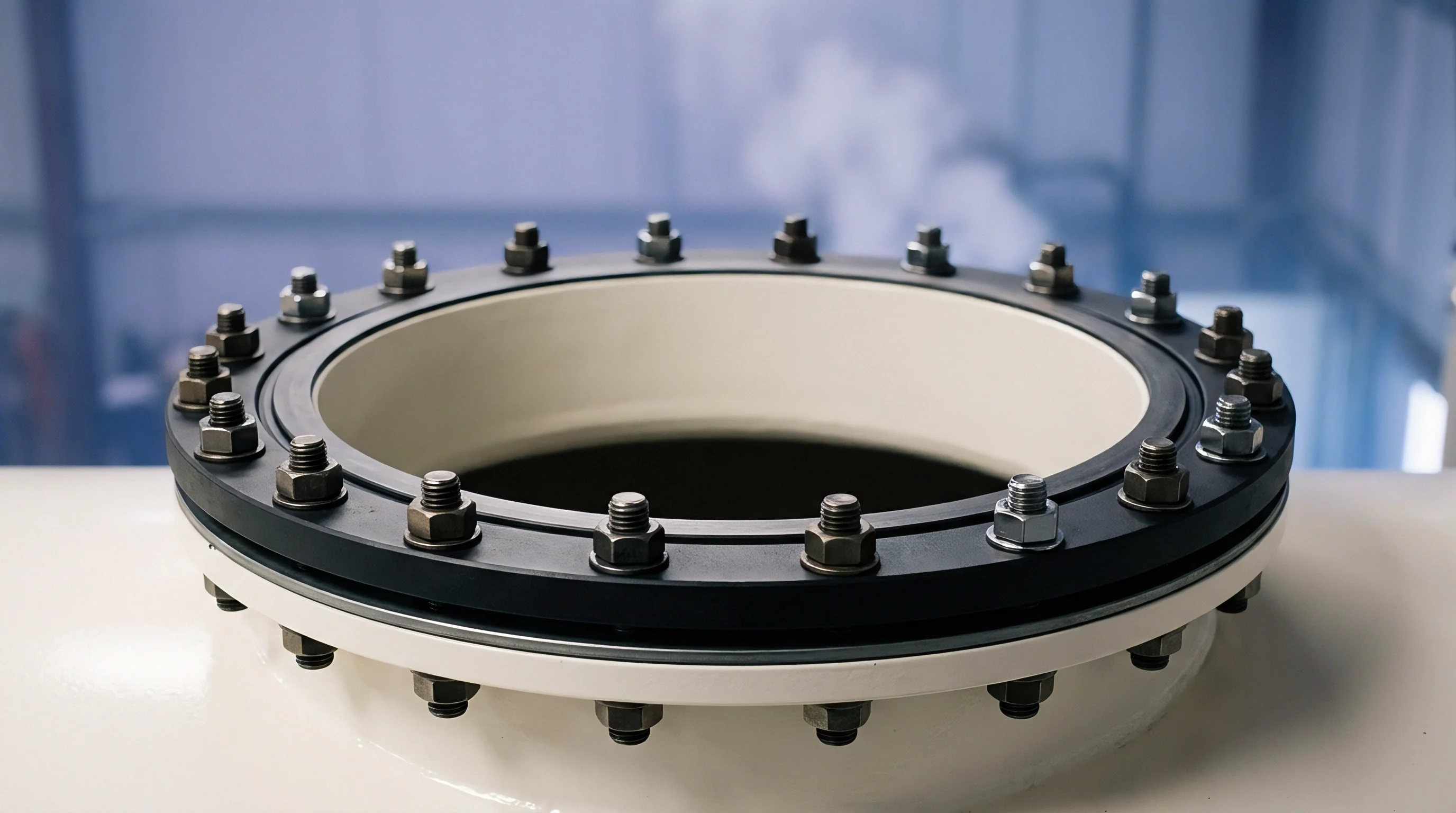
Subtractive modifications during qualification rely on high-speed CNC milling, surface grinding, wire EDM, and sinker EDM. Work typically begins after T1 trials show part dimensions exceeding CAD models because polymer shrinkage was lower than anticipated. Prior to metal removal, the insert’s heat treatment, tempering history, and structural support must be evaluated.
Removing steel from an unsupported core leg risks flexure under peak injection pressure, generating sporadic flash along the shut-off land.
Hard milling steels such as 1.2344 or 1.2383 at 50 HRC requires carbide end mills with titanium aluminum silicon nitride coatings. Tool paths should maintain light radial engagement and high axial depth to minimize heat transfer into the insert body. Excessive cutting heat induces localized tempering that softens steel along the cut path, creating premature wear points under abrasive glass-filled resins.
Executed correctly, high-speed hard milling achieves surface finishes down to Ra 0.2 microns, eliminating hand benching on non-textured cosmetic surfaces.
ISO 2768 fine tolerance classes apply to steel tooling geometries, but achieving part compliance under DIN 16742 Tg4 demands that metal removal accounts for localized mold deflection under full clamp tonnage.
Wire EDM remains the preferred method for modifying closed profiles, core pin locations, and rib geometries. Running an electrical potential between a moving brass wire and the steel workpiece erodes metal through controlled sparks inside a dielectric bath. Submerged wire EDM cuts hardened steel without creating significant thermal zones that alter core hardness, producing a uniform matte finish.
Skim passes at low peak currents limit the recast layer to under 0.002 mm, requiring only light diamond polishing.

Subtractive Engineering and EDM Relief Protocols
Sinker EDM remains essential for modifying deep internal cavities, thin ribs, and textured features beyond the reach of end mills. Electrode material determines accuracy: copper-tungsten resists spark erosion during deep burns, preserving corner radii down to 0.05 mm. Isotropic graphite achieves higher metal removal rates, but edge wear necessitates dedicated CNC-machined electrodes for roughing and finishing to prevent oversized radii in the cavity.
- Electrode CAD Modeling ~ Extract the negative volume from the revised part CAD model, applying spark gap offsets from 0.02 mm for finishing to 0.10 mm for roughing.
- CNC Electrode Machining ~ Mill high-density graphite electrodes on 5-axis centers with diamond-coated tooling to hold profile accuracy within 0.005 mm.
- CMM Inspection of Electrodes ~ Scan electrode surfaces on a coordinate measuring machine to verify that wear margins and spark gaps match the mod plan.
- Dielectric Flush Calibration ~ Set up multi-channel flush nozzles around the insert to clear eroded metal particles, avoiding secondary arcing and pitting.
- Sinker EDM Execution ~ Burn the cavity feature using adaptive orbit paths to distribute spark energy evenly across the steel surface.
- Recast Layer De-burring ~ Polish the burned area with ultrasonic stones, stepping from 320 up to 1200 grit to remove damaged thermal layers.
Subtractive operations must not compromise internal cooling channels. Deepening steel-safe relief in a cavity block thins the wall section separating the moulding surface from water lines. Maintaining at least 6.0 mm of steel between cooling channels and the cavity wall prevents thermal fatigue cracking and leakage under 6 bar operating pressure.
Precision ultrasonic thickness gauges should confirm remaining wall stock before commencing heavy milling on modified cavity floors.
Deepening ribs to improve resin flow alters local cooling and structural stiffness. When rib thickness exceeds 60 percent of the adjacent nominal wall, sink marks appear on opposing class-A surfaces. Flow relief cuts must be balanced against shrinkage behavior.
If engineering changes require deeper ribs, machining should proceed in 0.05 mm increments followed by press-side trials to verify that flow improvements do not compromise cosmetic surfaces.
Subtractive metal removal on hardened steel achieves highest accuracy when initial cuts are taken at half the measured part error.


Weld
Additive modifications become necessary when T1 dimensions show undersized wall sections, over-cut core details, or when engineering revisions introduce new features to existing inserts. Micro-TIG welding and laser wire deposition represent the primary methods for restoring metal to core and cavity blocks. Both processes induce thermal stresses: melting filler wire onto hardened tool steel creates a fusion zone, a heat-affected zone, and residual tensile stresses that reduce tool life if left unmanaged.
Laser welding provides controlled heat input, focusing energy into spot diameters between 0.2 mm and 1.5 mm. Proper calibration of pulse duration, frequency, and peak power melts filler wire without excessive thermal transfer into surrounding tool steel. This localized thermal profile prevents core annealing and distortion.
It is effective for restoring delicate shut-off faces, rebuilding worn core pins, and depositing stock on isolated ribs without disturbing adjacent polished surfaces.
Laser welding P20 or H13 steel without localized preheating generates martensitic shear stresses that cause micro-cracking along the heat-affected zone boundary during full-scale injection cycling.
Matching filler metal composition to the base steel preserves uniform mechanical properties and polishing response across the insert. Depositing generic stainless wire on an AISI H13 cavity block creates a localized hardness boundary with a mismatched thermal expansion coefficient, producing visible witness lines on moulded parts following diamond polishing or texturing. Selecting matching filler stock maintains grain structure, wear resistance under glass-filled resins, and chemical etching performance across the weld boundary.
Why Do Laser Welds Sink after Polishing?
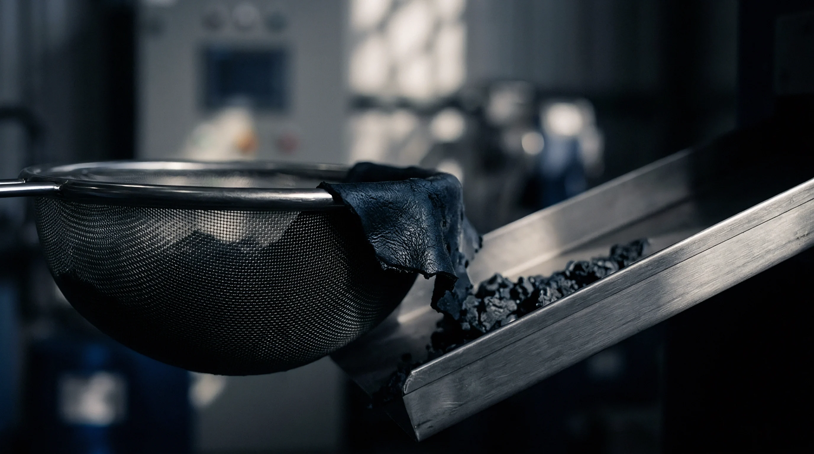
Polishing over laser repairs frequently reveals shallow depressions or halo rings around the weld boundary. This condition stems from hardness gradients between parent steel, heat-affected zones, and the deposited weld bead. A polishing stone or diamond compound abrades softer microstructures faster than adjacent hard zones.
Hardness variations across typical weld zones and corresponding tempering requirements are detailed below.
| Base Steel Grade | Filler Wire Material | As-Welded Bead Hardness | Heat Affected Zone Hardness | Post-Weld Tempering Temperature |
|---|---|---|---|---|
| AISI P20 (1.2311) | P20 Laser Wire | 34 – 38 HRC | 42 – 46 HRC | 480 – 520 deg C |
| AISI H13 (1.2344) | H13 High-Toughness Wire | 52 – 56 HRC | 58 – 62 HRC | 540 – 560 deg C |
| Stavax ESR (1.2083) | Stavax Laser Wire | 48 – 52 HRC | 54 – 58 HRC | 300 – 350 deg C |
| NAK80 (Age-Hardened) | NAK Specific Wire | 38 – 42 HRC | 32 – 36 HRC | 480 – 500 deg C |
Addressing these hardness differentials requires post-weld heat treatment. Subjecting the insert to stress relief or furnace tempering transforms untempered martensite at the fusion boundary, uniforming hardness across the repair. Preheating the insert to 250 ~ 300°C before extensive laser or TIG welding slows the cooling rate and prevents micro-cracking during martensite formation.
Omitting preheat and post-weld tempering invites micro-spalling and premature fatigue failure under cyclic injection pressures.
Micro-TIG welding remains practical for substantial buildup work where larger deposit volumes are required. Delivering low-amperage pulses between 2 and 50 amperes under an argon shield, it transfers higher heat into the insert than laser welding, requiring preheating up to 350°C and strict inter-pass thermal management. Micro-TIG deposits must be ground or sinker-EDMed back to target dimensions before stone polishing integrates the repair with the cavity surface.
Un-tempered laser welds across core shut-off faces in multi-cavity tooling risk micro-spalling after forty thousand cycles, causing press downtime and requiring complete replacement of core inserts.


Trace
Dimensional verification bridges trial moulding and steel modifications. Once a tool undergoes T1 or T2 adjustments, confirming steel geometry requires structured part scanning and statistical evaluation. Standard procedure involves running parts under stable press parameters, collecting representative samples across all cavities, and measuring critical callouts using CMMs, 3D optical scanners, or CT tomography.
Differentiating moulding process variation from tool steel errors is critical during trace analysis. Melt temperature, hold pressure, injection velocity, and cooling circuit design directly influence part dimensions. Conducting gate seal studies, viscosity curves, and cooling optimization establishes a stable scientific moulding window prior to CMM inspection.
Measuring parts from an unstable process run prompts unnecessary steel cuts, altering sound metal to correct transient thermal or pressure fluctuations.
DIN 16742 Tg3 tolerance standards require part thermal equilibrium at 23 deg C and fifty percent relative humidity for twenty-four hours before dimensional inspection.
Overlaying 3D optical scan point clouds onto master CAD models produces color-coded deviation heat maps. These maps reveal global distortion, volumetric shrink imbalances, and wall planarity. Red zones indicate material excess where steel removal is needed, whereas blue zones highlight starved areas where shrinkage pulled inward or additive welding is required.
Heat maps allow engineers and toolmakers to identify dimensional drift without sifting through extensive CMM data sheets.

Verification Matrices and Process Stability Gates
Translating CMM inspection data into steel modification instructions requires a disciplined verification matrix. Every critical drawing dimension must correlate directly to specific tool features across all cavities. If one cavity produces compliant parts while adjacent cavities fail, the cause points to flow imbalance, non-uniform cooling, or insert machining variation.
Pre-requisite documentation for authorizing steel modifications includes the following items.
- Scientific Moulding Process Sheet ~ Documented barrel profiles, injection speeds, peak cavity pressures, and hold pressure curves verified during sampling.
- Gate Seal Study Data ~ Graphic proof that gate freeze occurred before hold pressure released, ensuring consistent shot weight in each cavity.
- Cavity Balance Analysis ~ Full-shot weight comparison showing fill variation below 2.5 percent across all cavities.
- CMM Measurement Report ~ Complete inspection covering 100 percent of drawing dimensions for five consecutive parts per cavity.
- Environmental Conditioning Log ~ Temperature and humidity records confirming parts were conditioned for twenty-four hours before scanning.
- Tool Steel Modification Request Form ~ Formal engineering change document mapping specific steel cuts or welds, signed by process and tooling leads.
Process capability metrics determine whether steel modifications are necessary. Calculating Cp and Cpk separates random process variation from true tooling errors. A Cpk below 1.33 with a shifted mean indicates a geometric defect requiring steel adjustment.
Conversely, a low Cpk with broad scatter around nominal signals process instability, indicating press pressures, temperatures, or clamp parameters should be adjusted before altering steel.
Re-verification following modifications requires inspecting parts produced under the identical press parameters, resin lot, and ambient conditions used during initial trials. Altering barrel temperatures or changing resin lots between T1 and T2 invalidates comparative data. Maintaining fixed baseline conditions isolates tool modification as the sole variable, confirming whether milling or welding brought dimensions within specification.
Determining acceptable cavity-to-cavity variance as natural thermal variation vs. requiring individual insert re-machining remains a critical threshold in tool qualification.


Log
Managing tool modifications during qualification requires disciplined documentation. Every alteration to cores, cavities, lifters, or slides must be recorded in a central Tool Engineering Change Order log. Undocumented press-side adjustments during trials generate phantom geometries that render master CAD files obsolete, causing delays and expense when ordering replacement inserts.
A centralized modification log serves as the primary authority for the project team, contract moulder, and toolroom. Each entry should record the change rationale, drawing revision numbers, measured deviations, approved machining steps, and technician signoffs. Strict version control across part drawings, mold assembly CAD models, and physical tool steel prevents machining against outdated engineering revisions.
Undocumented press-side stoning of core pin shut-offs creates geometry shifts that bypass revision control and corrupt asset management databases.
Procurement contracts must clearly delineate commercial responsibility for modifications during qualification. Revisions driven by buyer design changes warrant paid engineering change orders. Conversely, modifications required to correct machining errors, missed steel-safe margins, or cavity imbalance remain the toolmaker’s responsibility.
Establishing these terms upfront prevents financial disputes and project delays.

Commercial Governance and Asset Signoff Protocols
Cross-border tooling management introduces regulatory and logistical considerations during modification cycles. Transporting inserts from a moulding facility to an external toolroom requires clear documentation regarding customs classification, ownership identification, and transit liability. Proper documentation prevents unexpected import tariffs on declared asset values.
Managing tool modifications under international contracts follows a structured operational sequence.
- Issue Dimensional Non-Conformance Report ~ Quality engineering issues an official report flagging out-of-spec dimensions tied to specific tool features.
- Root Cause Analysis and Responsibility Allocation ~ Engineering determines whether the discrepancy stems from drawing updates, process variation, or toolmaker error.
- Draft Tool Engineering Change Order ~ Engineering details the exact subtractive or additive work required, attaching updated 3D CAD files.
- Commercial Approval Gate ~ Sourcing leads approve budget and timing based on agreed responsibility.
- Steel Modification Execution ~ Toolmakers carry out approved milling, EDM, grinding, or welding under controlled shop conditions.
- Insert Re-qualification and Scan Log ~ Toolmakers scan modified inserts and update master assembly CAD before putting inserts back into the mold base.
Effective asset management relies on physical identification on modified inserts to maintain lifecycle traceability. Laser-etching revision codes, execution dates, and cavity identifiers onto non-functional insert surfaces ensures replacement spares match active tool configurations. Omitting physical tags creates ambiguity when pulling spare components from inventory for maintenance rebuilds.
Qualification concludes with formal asset signoff, transferring physical custody and commercial release from toolmaker to production moulder. Final release requires a complete qualification dossier containing material certificates, stress-relieving records, CMM inspection reports, approved process sheets, and the change history log. This documentation confirms that physical tool steel matches master CAD files and that all modifications have been validated.
Final signoff on tool modifications requires written authorization from technical sourcing management within two business days of trial report delivery before metal removal or deposition proceeds.

Title
The final qualification phase establishes legal ownership, production approval, and transfer of the validated mold. Transitioning into series production shifts commercial tooling risk from toolmaker to buyer. A clean transfer requires verifying that all modifications executed across T0, T1, and T2 trials are reflected in as-built CAD files archived by the buyer.
Supply contracts establish performance thresholds required before final payment and ownership transfer. A tool producing compliant parts during a short T1 sample run may drift out of tolerance during continuous multi-shift production. Acceptance criteria typically require process capability to exceed Cpk 1.67 across extended runs, verifying that thermal management, venting, and steel dimensions remain stable under full operating loads.
Establishing physical ownership requires clear marking on the mold base and internal inserts. Tooling agreements specify mounting anodized aluminum or stainless steel asset plates to the mold frame detailing owner identification, asset numbers, mold weight, dry cycle time, maximum injection pressure, and electrical specifications. Physical plates safeguard customer assets against unauthorized production or inclusion in commercial collateral.
Spare insert management forms an essential component of production readiness. High-wear features ~ such as thin shut-off edges, core pins under 1.0 mm, or heavily welded zones ~ warrant duplicate inserts manufactured during initial tool fabrication. Procuring spares concurrently reduces unit cost and ensures replacement components undergo identical heat treatment and EDM processing, eliminating variability during high-volume maintenance.
Core documentation deliverables required for complete tooling asset transfer and commercial signoff are summarized below.
| Deliverable Name | Document Type | Primary Content / Coverage | Signoff Authority |
|---|---|---|---|
| As-Built 3D Tool Assembly CAD | 3D CAD File (STEP / IGES) | Fully updated tool assembly matching physical modified steel inserts | Lead Tooling Engineer |
| Tooling Modification History Log | Signed Engineering Dossier | Complete history of all additive/subtractive cuts, TECOs, and welder logs | Sourcing Quality Manager |
| Final CMM Capability Report | Statistical Analysis Data | Cpk calculations proving dimensional compliance across all cavities | Plant Metrology Lead |
| Preventative Maintenance Schedule | Technical Maintenance Manual | Greasing intervals, seal replacement schedules, and wear face limits | Production Moulding Lead |
| Asset Physical Marking Verification | Photographic Inspection Record | Clear photos of installed asset plates and etched insert revision codes | Commercial Asset Auditor |
Relocating an injection tool to an alternate manufacturing plant exposes omissions in modification documentation. Unrecorded press-side stoning, manual gate adjustments, or undocumented relief grinding prevent subsequent moulders from reproducing part quality using baseline CAD files. Seamless relocation depends on complete alignment between physical tool steel and digital engineering models, enabling qualified toolrooms to produce drop-in replacement inserts without manual fitting.
Approval of the final tooling milestone releases escrow funds and authorizes commercial production. Sourcing teams enforce structured approval gates requiring physical tool inspection, dimensional verification, and CAD synchronization prior to signoff. Methodical validation transforms tool qualification into a controlled engineering process that protects capital investment and ensures consistent production quality.
Asset transfer concludes when physical possession of the fully documented mold base is transferred alongside as-built CAD models, stress-relieving certificates, and verified spare inserts ready for immediate press deployment.