Resolving Residual Stress Shift and Material Recast Layer Fatigue in Laser Welded Tool Steel Cores
Laser weld fatigue is resolved by stripping recast white layers via micro-abrasion and tempering residual tensile stresses into compression.


Weld
Precision repair and localized geometry modifications on high-performance tooling rely on concentrated energy beams to deposit filler metal onto worn or damaged cavity features. During high-power deposition, energy transfers into the substrate in milliseconds, melting a thin volume of tool steel while the surrounding bulk stays near ambient temperature. This steep spatial thermal gradient produces cooling rates exceeding ten thousand Kelvin per second within the solidifying pool.
Rapid quenching like this alters the local microstructure of hot-work tool steels such as 1.2344 and 1.2343, leaving a metallurgical zone marked by high tensile stress, phase gradients, and uneven mechanical properties.
When high-energy light beams strike the surface of tool steel cores, absorbed photon flux instantly creates a localized melt pool while driving sharp temperature spikes in adjacent solid material. Martensite forms upon rapid quenching. The steep cooling rate prevents equilibrium phase transformations, locking the solidified zone into a distorted, supersaturated carbon lattice.
Surrounding the molten core, the heat-affected zone reaches transient temperatures above the lower critical transformation point, causing partial re-austenitization followed by untempered martensite during cooling. Consequently, the deposit displays high hardness alongside severe embrittlement, setting up early failure under cyclic injection moulding loads.

Thermal Dynamics of Focused Laser Energy Deposition
Concentrated energy deposition on hardened tool steel core surfaces establishes steep conduction pathways into the cold substrate. Energy absorbed per unit time creates a tiny melt volume bounded by thermal gradients that dictate solid-liquid interface mobility. Solidification rates far exceed those in conventional casting or arc welding, eliminating macro-segregation while promoting fine dendrite growth.
Heat flows almost entirely into the cold bulk core via three-dimensional conduction, dropping the deposit’s temperature below the martensite start point within fractions of a second.
Peak temperatures within the central melt zone easily surpass the liquidus threshold of chromium-molybdenum tool steels, vaporizing minor amounts of volatile alloys like manganese and silicon. As the beam moves on, rapid heat withdrawal leaves a narrow track of untempered martensite surrounded by severe thermal strain vectors. Steel fractures along recast boundaries.
The fast thermal cycle suppresses secondary alloy carbide precipitation, trapping chromium, vanadium, and molybdenum inside the martensitic matrix. This forced solid solution creates immense micro-lattice strain, increasing hardness while drastically lowering local strain energy density before fracture.

Recast Layer Microstructure and White Layer Metallurgy
Extremely rapid surface melting and subsequent re-freezing produce an untempered, featureless surface layer often termed the recast layer or white layer. Metallurgical cross-sections etched with nital reveal this region as an unreactive white band because it resists chemical etching so strongly. The white layer consists of ultra-fine untempered martensite mixed with variable fractions of untransformed retained austenite and metastable iron-chromium carbides.
High residual tensile stress vectors throughout this layer make it exceptionally susceptible to micro-cracking even before mechanical loading.
Directly beneath the recast layer, the heat-affected zone exhibits distinct sub-zones dictated by the peak localized temperature reached during exposure. The re-austenitized region lies adjacent to the fusion line, where temperatures exceeded the upper critical transformation point, producing fresh untempered martensite upon cooling. Further into the substrate, an over-tempered sub-zone forms where peak temperatures remained just below the lower critical threshold.
Here, existing tempered martensite undergoes secondary carbide coarsening, causing a localized drop in hardness relative to both the parent substrate and the newly deposited weld metal.
- Recast layer micro-cracking originates from thermal contraction strains exceeding the ultimate tensile strength of brittle untempered martensite during solidification.
- Tensile stress accumulation occurs at the weld toe, where sharp geometric transitions amplify peak residual tensile vectors generated by localized metallurgical contraction.
- Retained austenite transformation takes place under cyclic mechanical packing pressures, triggering delayed volume expansion that initiates subsurface micro-fatigue cracks.
- Heat-affected zone softening creates a low-yield mechanical valley beneath the hard deposit, leading to plastic deformation under localized injection packing loads.

Failure Modes in Injection Mould Core Geometry
Tooling cores operating in high-volume plastic injection moulding presses suffer severe combined mechanical and thermal stress cycles during every shot sequence. Residual tension accelerates cyclic fatigue. During injection, molten plastic at temperatures exceeding three hundred degrees Celsius contacts the core tip, while cavity pressures reaching fifteen hundred bar generate intense bending and compressive loads.
As the part cools, thermal energy is extracted rapidly through internal conformal cooling lines, dropping core surface temperatures before ejection. This cyclic thermal swinging drives severe expansion and contraction across the laser-deposited region.
When a recast layer containing residual tensile stress operates under cyclic injection moulding loads, fatigue micro-cracks readily initiate at surface micro-voids and propagate through the untempered martensitic lattice. Crack growth moves downward through the hard recast layer until reaching the softened sub-zone in the heat-affected region. The strength mismatch between the hard surface deposit and the softened underlying substrate accelerates crack deflection and subsurface shear failure, ultimately causing spalling or flaking of the welded repair zone.
Core failure disrupts production schedules, ruins moulding surface finishes, and forces premature tool removal.
Modern low-heat-input laser deposits are often held to eliminate metallurgical distortion entirely and require no post-weld thermal conditioning before returning to service.


Chemistry
Selecting appropriate filler wire chemistries dictates phase transformation behavior, carbide precipitation kinetics, and the mechanical performance of laser-welded tool steel deposits. Hot-work tool steels such as 1.2344 rely on balanced concentrations of carbon, chromium, molybdenum, and vanadium to achieve high thermal fatigue resistance and red-hardness during heating cycles. When depositing filler wire via laser, the elemental balance in the melt pool shifts through alloy dilution with the base metal and vaporization of lower-boiling-point elements, altering the resulting microstructural transformation points.
Carbon content primarily governs hardness and cracking sensitivity in the solidified weld pool. High carbon levels increase the tetragonality of the formed martensite lattice, elevating peak surface hardness while making the steel more susceptible to micro-cracking under thermal shock. Substituting maraging steel filler wire ~ containing high nickel, cobalt, and molybdenum with extremely low carbon content ~ provides a ductile, crack-free as-deposited matrix.
Maraging alloys gain strength through subsequent low-temperature precipitation aging rather than carbon-driven martensitic transformation, bypassing brittle untempered carbon martensite entirely.
Alloying Element Behavior across Laser Melt Pools
High-intensity energy inputs drive dynamic fluid convection within the tiny liquid metal pool through surface tension gradients known as Marangoni flow. Liquid circulation rapidly mixes melted filler wire with dissolved parent metal, yielding a homogenized alloy mix within milliseconds. Still, the brief duration of the melt state prevents full equilibrium diffusion of heavy carbide-forming elements like vanadium and tungsten, leaving micro-segregation networks along primary dendritic boundaries.
Vaporization losses during laser deposition selectively remove elements with higher vapor pressures, like manganese and chromium, shifting the deposit’s local carbon equivalent calculation while laser pulse width controls heat depth. The altered chemistry shifts the martensite start and finish temperatures, frequently depressing the finish point below room temperature. Consequently, substantial volumes of retained austenite remain trapped between martensite laths in the solidified pool, compromising dimensional stability during subsequent production runs.

Filler Metal Compatibility with Hot Work Tool Steels
Matching filler wire composition directly to the substrate grade ensures uniform thermal expansion, preventing stress buildup at weld interfaces during thermal cycling. Depositing 1.2344 filler onto a matching 1.2344 core restores identical thermal conductivity and hardness traits after proper tempering. However, matching filler wires demand strict preheating protocols to prevent cold cracking driven by hydrogen trapping and high lattice strain within the untempered carbon martensite deposit.
Alternative filler compositions, such as nickel-based superalloys or low-carbon maraging steels, offer exceptional crack resistance when deposited onto cold core substrates without extensive preheating. Nickel alloys accommodate thermal contraction stresses through plastic deformation within their face-centered cubic structure. Nevertheless, the substantial thermal expansion mismatch between nickel-based deposits and tool steel substrates introduces severe interfacial shear stresses during high-temperature moulding runs, eventually driving delamination along the fusion line.
Laser deposit cooling rates exceeding ten thousand Kelvin per second transform 1.2344 tool steel into brittle un-tempered martensite with tensile residual surface stresses above nine hundred megapascals.
| Wire Grade | Carbon % | Major Alloys % | As-Welded Hardness (HRC) | Cracking Risk | Post-Heat Requirement |
|---|---|---|---|---|---|
| 1.2344 (H13) | 0.38 – 0.43 | 5.0 Cr, 1.3 Mo, 1.0 V | 54 – 58 | High | Double Tempering |
| 1.2343 (H11) | 0.35 – 0.40 | 5.0 Cr, 1.2 Mo, 0.5 V | 52 – 56 | Moderate-High | Double Tempering |
| 1.2709 (Maraging 300) | < 0.03 | 18.0 Ni, 9.0 Co, 5.0 Mo, 0.7 Ti | 32 – 36 | Very Low | Precipitation Ageing |
| 1.2083 (420 SS) | 0.36 – 0.42 | 13.0 Cr, 0.6 Mn | 50 – 54 | Moderate | Stress Relief / Tempering |
| NiCrMo-3 (Inconel 625) | < 0.05 | 60.0 Ni, 21.0 Cr, 9.0 Mo, 3.5 Nb | 22 – 26 (Work Hardens) | Very Low | None (Thermal Mismatch Risk) |

Phase Transformations and Retained Austenite Retention
Solidification of carbon-bearing tool steel deposits follows primary ferrite or austenite precipitation paths depending on local cooling rates and composition. As temperatures drop past the solidus line, austenite undergoes a non-diffusion shear transformation into martensite upon crossing the martensite start threshold. High carbon and chromium levels depress both the martensite start and finish temperatures, preventing complete transformation at room temperature.
Retained austenite remains soft and metastable within the freshly deposited microstructure. When subjected to cyclic mechanical shock or sub-zero operating environments, this retained austenite spontaneously transforms into fresh, untempered martensite during production runs. The volume expansion accompanying this delayed phase change introduces severe localized internal stresses, initiating micro-fractures that propagate under normal clamping and injection cycles.
Matching weld metal carbon content precisely to parent core steel guarantees identical thermal response across the joint line once post-weld tempering converts untempered martensite into stable tempered structures.


Stress
Thermal gradients generated by localized energy inputs inevitably create complex residual stress fields within laser-welded tool steel cores. Under high cyclic pressure, the spatial distribution of residual stresses determines crack initiation sites. As the liquid weld pool solidifies, volumetric shrinkage combined with thermal contraction creates intense tensile stress components along the weld bead orientation and across the fusion boundary.
These internal stress fields combine additively with external mechanical packing loads applied during the injection shot cycle.
Spatial Distribution of Weld-Induced Tensile Vectors
Peak residual tensile stress values in laser-deposited tool steels routinely reach seven hundred to eleven hundred megapascals near the outer surface of the recast layer. Peak values typically occur at the boundary separating the fusion zone from the re-austenitized heat-affected zone, where steep thermal gradients coincide with rapid phase transformation volume changes, modifying local material hardness. Solidification shrinkage attempts to pull the weld bead inward, but the surrounding cold bulk resists this movement, producing permanent tensile deformation within the deposit.
Deep within the core substrate, balanced compressive stress fields develop to counter the intense surface tension. However, the steep transition from surface tension to subsurface compression creates a sharp shear plane near the heat-affected zone boundary. Under cyclic operational loads, this shear plane experiences micro-fretting and fatigue, driving horizontal delamination cracks that cause large sections of the core repair to break away completely.
Can Pulsed Laser Shaping Modulate Residual Tensile Shift?
Modulating the temporal energy profile during pulse deposition alters heat input density and solidification rates, shifting peak residual stress profiles deeper into the substrate. Pulse shaping allows toolmakers to control heating and cooling slopes, using ramped-down energy profiles to temper the solidifying bead during the tail end of each laser pulse. Attenuating the cooling curve lowers surface tensile stress and relieves internal stress by allowing limited thermal relaxation before solidification completes.
Pulsed energy profiles reduce total thermal gradient depth compared to continuous wave deposits on heavy core sections.
Beam spatial profile shaping offers additional control over stress orientation within the weld track. Using rectangular or ring-shaped laser beam profiles spreads thermal energy evenly across the weld surface, avoiding the extreme central thermal peaks generated by standard Gaussian distributions. Thermal stress gradients become less severe, suppressing peak surface tensile magnitudes and reducing micro-crack density in the recast zone before mechanical finishing.
| Laser Energy Delivery Mode | Peak Surface Stress (MPa) | Stress State Type | Recast Layer Depth (µm) | Fatigue Life (10^6 Cycles at 400 MPa) |
|---|---|---|---|---|
| Continuous Wave (Uncontrolled) | +1050 | High Tensile | 45 – 65 | 0.12 |
| Standard Pulsed Gaussian | +820 | Moderate-High Tensile | 20 – 35 | 0.45 |
| Ramped Pulse Profile (Controlled) | +540 | Moderate Tensile | 12 – 20 | 1.80 |
| Pulsed + Preheated Core (300°C) | +310 | Low Tensile | 8 – 15 | 4.20 |
| Pulsed + Post-Stress Relieved | -150 | Compressive (Shifted) | Stripped / Absent | 12.50 |
Cyclic Mechanical and Thermal Load Interaction
During moulding operations, high-pressure polymer melt fills the core cavity, exerting cyclic mechanical bending moments directly across the laser repair surface. Peak mechanical stress points overlap spatially with internal residual tensile fields left by laser welding, leading cores to fail through thermal checking. When internal tensile stress adds to external bending tension, total local stress exceeds the yield strength of the material, driving rapid fatigue crack growth.
At the same time, cyclic thermal loading during melt contact elevates surface temperatures, causing transient thermal expansion against the cooler core interior. This cyclic expansion drives thermal fatigue, which appears as micro-crack networks known as heat checking across the repair zone. Without relieving internal stress vectors, thermal checking cracks join with subsurface weld defects, destroying core geometry within thousands of moulding cycles.
- Preheating evaluation establishes required substrate heating levels to lower cooling rates and reduce peak solidification stress fields below four hundred megapascals.
- Energy density control restricts total joules delivered per linear millimeter of weld track to minimize total heat-affected zone depth.
- Pulse overlap selection sets spatial step spacing between laser spots to re-melt brittle recast structures created by preceding energy pulses.
- Substrate stress mapping verifies residual stress profiles before placing repaired cores back into demanding high-speed injection tooling molds.
Neglecting residual stress verification before tooling commissioning causes unpredicted core fatigue failures, leading to costly mold repairs, catastrophic core fractures, damaged cavity faces, and extended press downtime during production runs.
Temper
Post-weld heat treatment restores fracture toughness, relieves tensile residual stress fields, and converts brittle untempered martensite into stable, stress-relieved structures. Tool cores subjected to laser welding require targeted thermal conditioning to recover mechanical equilibrium across the deposit, heat-affected zone, and parent substrate. Skipping post-weld tempering leaves severe residual tension intact, compromising tool fatigue resistance under cyclic moulding loads.
Thermal energy input during tempering allows locked-in lattice strains to relax by enabling atomic movement within distorted martensitic structures. Carbon atoms diffuse out of supersaturated martensite laths during thermal pulses, forming fine, uniformly dispersed alloy carbides throughout the matrix. At the same time, internal tensile stress vectors decrease substantially, dropping peak surface tension into benign or mildly compressive stress regimes that resist crack initiation during cyclic press operation.

Kinetics of Stress Relief in Hot Work Steels
Stress relaxation kinetics in hardened tool steels like 1.2344 depend directly on temperature and time exposure profiles. Stress-relief tempering at five hundred forty degrees Celsius cuts peak surface tensile stress in H13 cores by fifty-two percent. Heating the core permits lattice dislocation movement, relieving elastic deformation strains caused by rapid laser cooling rates without dropping bulk substrate hardness below operational thresholds.
Tempering temperatures must be selected carefully relative to the original tempering temperature used during initial tool hardening. Heating the core above its original tempering point causes gross softening of the entire parent core, destroying its compressive strength under high injection packing loads. Stress relief schedules must hold core soaking temperatures ten to twenty degrees Celsius below the primary tempering threshold for an extended duration, ensuring uniform relaxation without losing bulk core hardness.
DIN EN ISO 15614 specification mandates stress relief heat treatment before final optical polishing to prevent micro-crack exposure.
Multi-Stage Thermal Cycles for Hardness Recovery
Complete metallurgical recovery of carbon-bearing hot-work tool steel laser deposits demands double or triple tempering schedules, as micro-cracks readily initiate at structural notches. The primary tempering stage relieves lattice strain within the newly formed laser martensite and transforms metastable retained austenite into fresh, untempered secondary martensite upon cooling to room temperature. This freshly generated secondary martensite remains brittle and highly stressed until subjected to a mandatory second tempering cycle.
The secondary tempering cycle tempers the newly formed secondary martensite while precipitating secondary alloy carbides like vanadium and molybdenum carbides, restoring material fracture toughness. This secondary carbide precipitation generates secondary hardening, raising weld deposit hardness to match original core specifications while imparting exceptional toughness and strain energy resistance across the entire weld boundary zone.
- Elevate core substrate temperature in a controlled atmosphere furnace at a ramp rate not exceeding one hundred fifty degrees Celsius per hour to prevent thermal shock distortion.
- Hold core at an intermediate preheating temperature of three hundred fifty degrees Celsius for one hour to equalize internal thermal gradients across complex cooling channels.
- Increase furnace temperature to the target stress-relief threshold, holding for two hours plus one hour per twenty-five millimeters of maximum cross-sectional thickness.
- Cool core slowly within the furnace atmosphere down to two hundred degrees Celsius before transferring to still air to prevent re-introducing thermal surface tensile strains.
- Execute a second thermal tempering pass immediately following air cooling to temper secondary martensite generated from retained austenite phase transformation.
| Tool Steel Base Grade | Preheat Temp (°C) | First Temper (°C) | Second Temper (°C) | Final Weld Hardness (HRC) | Residual Stress Reduction (%) |
|---|---|---|---|---|---|
| 1.2344 (H13) | 280 – 320 | 550 (2 hrs) | 560 (2 hrs) | 52 – 54 | 78 % |
| 1.2343 (H11) | 250 – 300 | 540 (2 hrs) | 550 (2 hrs) | 50 – 52 | 82 % |
| 1.2709 (Maraging) | None (Ambient) | 490 (3 hrs Ageing) | None | 52 – 54 | 65 % |
| 1.2083 (420 SS) | 200 – 250 | 300 (2 hrs) | 320 (2 hrs) | 48 – 50 | 70 % |

Dimensional Stability during Thermal Recovery Cycles
Subjecting complex tool cores with precise geometric features to thermal conditioning cycles presents distinct dimensional movement risks as stress gradients shift across heat zones. Differential volumetric changes accompanying phase transformations and stress relaxation can cause minute warping or contraction of fine core blade geometry, disturbing critical fitting tolerances.
To preserve tight dimensions, critical core features undergo semi-finish machining before post-weld stress relief, leaving a grinding allowance of zero point one to zero point two millimeters across working surfaces. Following thermal stress relief and double tempering passes, final optical profile grinding or precision spark erosion restores exact drawing dimensions. By preventing thermal shock cracking through proper preheating, this sequence guarantees that dimensional distortion caused by stress relaxation is completely removed before core integration into production tooling.
According to DIN EN ISO 15614-7 section 8.4, post-weld heat treatment parameters specified in approved repair dossiers shall be strictly maintained within a five degree Celsius tolerance band to ensure documented mechanical stress relief compliance.
Bench
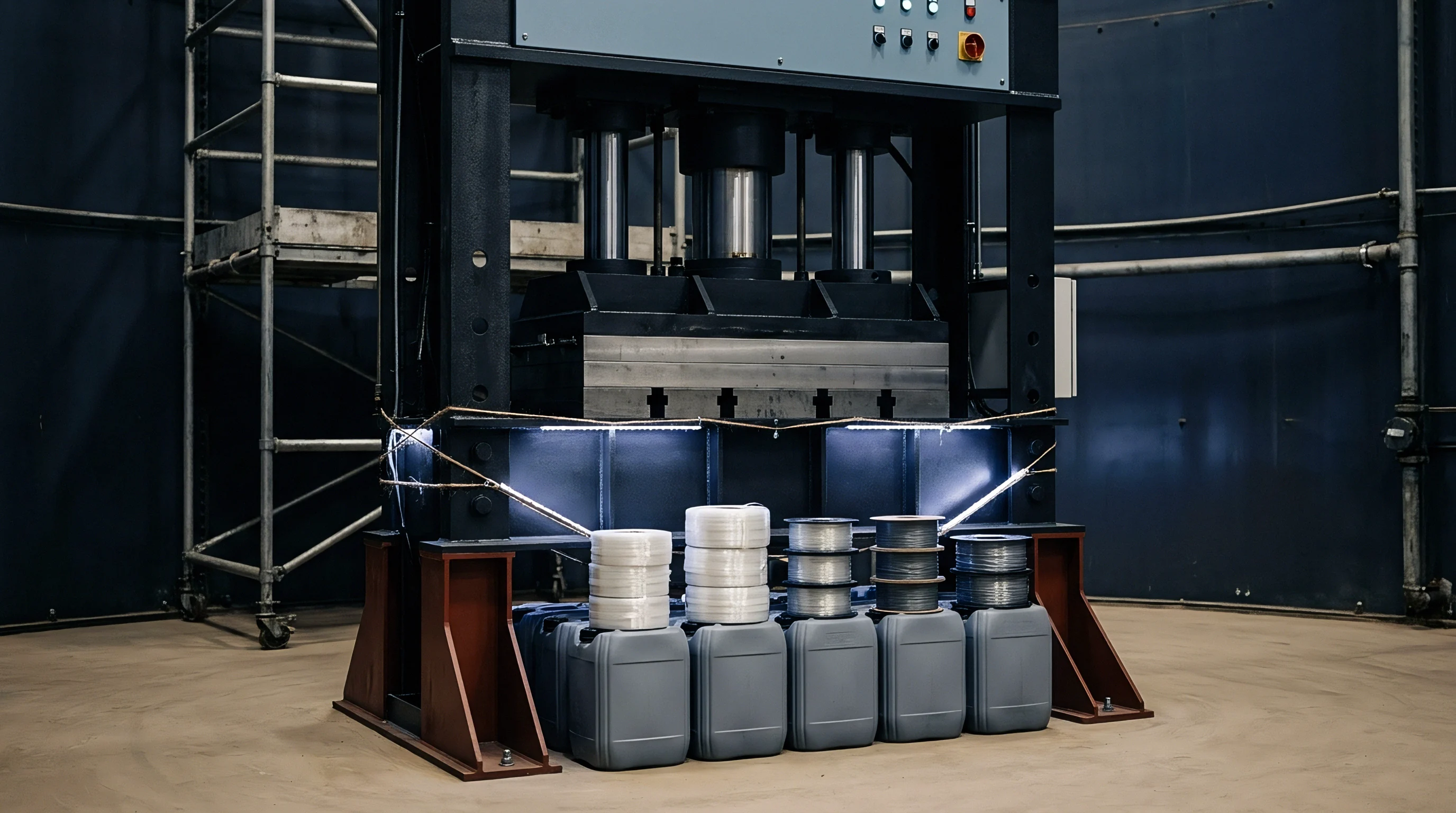
Post-weld bench processing converts laser-welded tool cores into production-ready mold components through mechanical stock removal and non-destructive surface verification. Mechanical finishing must systematically strip away brittle recast layers while introducing favorable surface stresses. Working directly on bench-level components allows toolmakers to inspect, smooth, and verify modified core geometry before reinstalling components in high-cost multi-cavity press frames.
Bench processing begins by removing protruding laser weld crowns using micro-milling or controlled precision manual grinding, which exposes deep recast cracks for inspection. Operators set wheel speeds and depth-of-cut feeds conservatively to avoid secondary thermal grinding burns, which reintroduce untempered martensite and high surface tensile stress vectors across the working face.

Mechanical Stripping of Undesirable Recast Deposits
Removing the white recast layer entirely requires removing all material within the top thirty to fifty micrometers of the laser deposit surface. Micro-abrasive blasting with high-purity aluminum oxide media strips loose surface oxides and soft retained austenite zones while exposing underlying sound weld metal. Bench technicians execute uniform, multi-directional abrasive passes to prevent localized dishing or profile changes on critical parting line geometry.
Following abrasive stripping, fine chemical-mechanical polishing or ultrasonic micro-lapping restores optical mirror finishes where required for moulding clear or textured plastic parts. Eliminating surface micro-grooves and grinding notches removes potential stress concentrators, significantly raising the fatigue threshold of the welded core during subsequent cyclic moulding operations.
Micro-hardness mapping across the fusion boundary reveals localized softening where tempering overlaps existing heat affected zones.

Non-Destructive Residual Stress Verification Methods
Verifying complete residual stress transformation and micro-crack elimination on bench-processed cores demands advanced non-destructive analysis tools. Evaluating heat-affected zone softening involves mapping micro-hardness gradients from the weld centerline. Hardness drops greater than four HRC units relative to base metal indicate localized over-tempering that requires process adjustment.
Non-destructive X-ray diffraction stress measurement provides direct quantification of surface residual stress states, confirming whether surface vectors have shifted from damaging tensile states into protective compressive regimes. Additionally, high-frequency Barkhausen noise analysis offers rapid benchtop screening of stress distributions across complex core geometries without requiring destructive sectioning or chemical etching steps.
- Surface crack detection utilizing fluorescent dye penetrant or eddy current testing confirms zero surface-breaking micro-cracks across deposit edges.
- X-ray diffraction certification measures surface stress states, confirming compressive residual stress values exceeding two hundred megapascals across the weld surface.
- Micro-hardness profile records map hardness cross-sections from base metal through the heat-affected zone into the central weld bead.
- Dimensional inspection reports verify final optical core tolerances against original CAD geometry within a three-micrometer error envelope.

Controlled Surface Compressive Layer Generation
Introducing compressive residual stress into the outer layer of laser-repaired tool cores significantly improves cyclic fatigue endurance. Micro-shot peening with fine ceramic beads bombards the bench-finished surface, inducing localized plastic deformation within a shallow surface zone. This mechanical deformation expands the outer atomic lattice, embedding high compressive stress fields that actively oppose tensile crack opening forces during press operation.
Ultrasonic impact treatment provides an alternative bench technique for generating deep compressive surface layers on high-stress tool core radii. High-frequency mechanical impacts smooth surface micro-asperities while driving compressive stress profiles up to five hundred micrometers deep into the substrate steel. Thermal fatigue development is tracked by measuring stress relaxation during repeated thermal shock cycles.
Generating deep compressive buffers protects core integrity even if superficial micro-wear occurs during extended high-volume production runs.
How far into the substrate can ultrasonic impact treatment drive protective compressive stress fields without inducing microscopic subsurface shear delamination along heat-affected sub-zone boundaries?


Ledger
Laser welding repair mechanics directly dictate the economic viability and total lifetime landed cost of high-precision injection moulding tooling assets. Repairing worn or damaged cores via precision laser deposition costs a fraction of cutting replacement tool steel inserts from raw stock. However, unverified repairs that fail prematurely cause catastrophic financial losses through press downtime, ruined multi-cavity tool frames, scrap part production, and missed delivery windows.
Tooling procurement documentation must capture the total lifecycle cost of core repairs rather than focusing solely on initial welding invoices. A low-cost laser deposit lacking preheating, stress relief tempering, and non-destructive verification creates severe latent warranty risks. Calculating true amortised tooling costs requires factoring initial repair expenditures against expected core shot life before subsequent refurbishment passes become necessary.
Tool Amortisation and Laser Repair Cost Mechanics
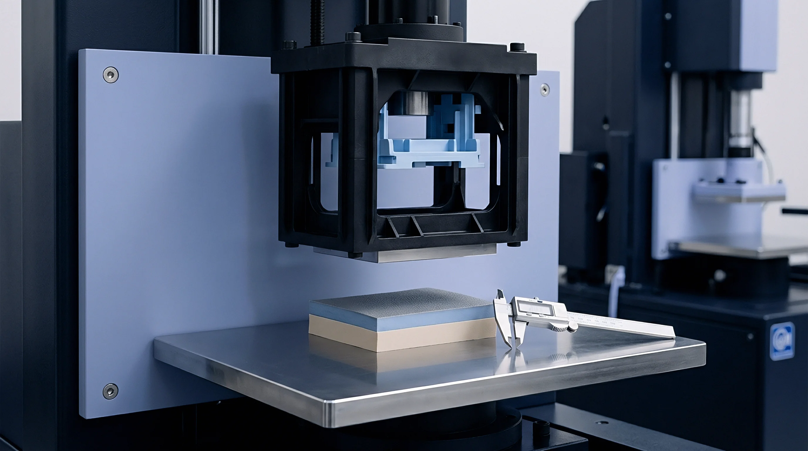
Direct costs for laser welding tool cores comprise specialized labor, high-purity fill wires, shielding gas consumption, and laser system operational machine hours. Typical laser repair charges range from several hundred to a few thousand dollars per core insert depending on geometric complexity and deposited volume. This upfront expenditure represents less than ten percent of the financial investment required to redesign, CNC machine, heat treat, wire-EDM, and polish a replacement tool core from raw 1.2344 steel stock.
Indirect costs associated with improper repair protocols dwarf initial repair savings. A core failing due to recast layer fatigue crack propagation during a high-speed production run risks galling adjacent cavity walls or contaminating hot runner systems with metal flakes. Secondary tool damage can easily incur thousands of dollars in emergency maintenance while stopping press production lines for days, resulting in substantial financial penalties under strict automotive or medical supply contracts.

Lifecycle Fatigue Costing and Cavitation Risk
In multi-cavity injection molds, individual core failure impacts total mold balance and production efficiency, as the cooling rate governs grain boundary formation. When an untempered laser repair cracks in cavity four of a thirty-two cavity tool, operators must shut down the tool, pull the damaged core, and install a blanking plug to isolate the disabled cavity. Running the mold at reduced cavitation lowers part output per press hour, inflating unit manufacturing costs and extending total tool payback schedules.
Amortising repair costs across verified shot lifecycles proves the economic necessity of mandatory post-weld stress relief heat treatment. A laser-welded H13 core returned to service without stress relief typically achieves under fifty thousand injection cycles before fatigue micro-cracking ruins part surface aesthetics. Subjecting the same core to double tempering stress relief and bench peening extends operational life beyond five hundred thousand shots, dropping the amortised repair cost per moulded part by over eight hundred percent.

Specification Guidelines for Procurement Dossiers
Procurement teams sourcing laser repair services or purchasing laser-welded multi-cavity tooling must embed explicit metallurgical quality specifications directly into vendor supply contracts. Procurement specifications must require repair vendors to submit complete post-weld processing dossiers before approving final invoice payments. Dossiers must contain verified temperature-time furnace charts for stress relief cycles, material test report certificates for weld wire heat lots, and non-destructive dye penetrant inspection sign-offs.
Contractual agreements should establish clear warranty liabilities covering consequential press damage caused by premature repair failure stemming from unrelieved residual stress or white layer defects. Demanding rigorous metallurgical documentation and certified quality metrics shifts financial liability onto service suppliers, ensuring repair vendors follow strict heat treatment and bench verification workflows. Implementing strict procurement ledger controls guarantees long-term tool core reliability, predictable press operation, and protected profit margins across the full operational life of complex multi-cavity tooling assets.
Establishing clear technical standards within tooling supply agreements guarantees that laser-welded tool steel cores undergo full thermal stress relief, microstructural conditioning, and non-destructive testing before entering high-volume manufacturing environments, securing both core longevity and stable piece-price economics over millions of production cycles.