Predicting Thermo Mechanical Micro Hobbing Depths across Heterogeneous Multi Material Shutoff Insert Assemblies
Micro hobbing depths in multi material shutoffs depend on thermal expansion mismatch and temperature reduced yield strength under cyclic clamp compression.

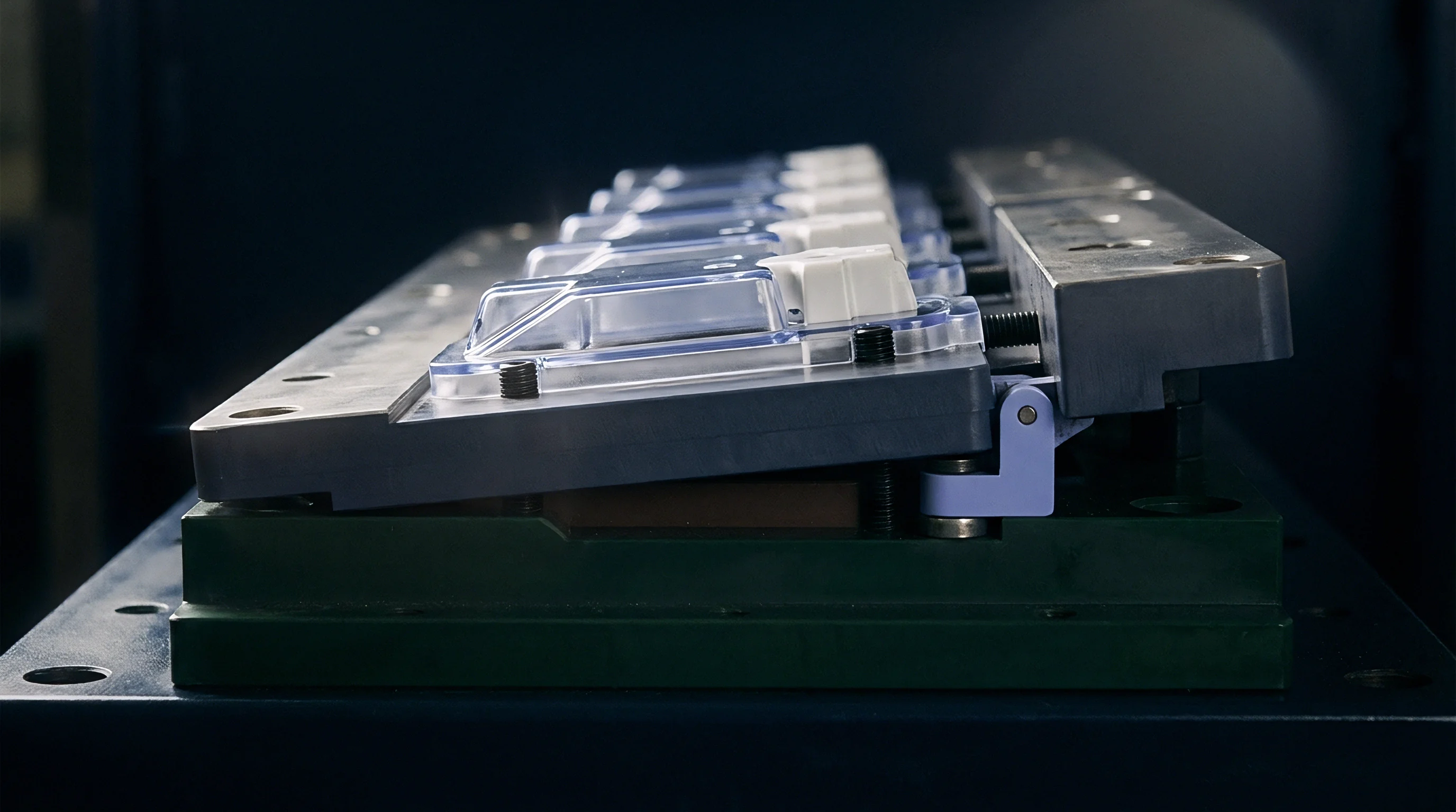
Yield
Compressive stresses exceeding material limits at shutoff insert boundaries initiate permanent physical indentation across parting line surfaces. In multi-material injection mold construction, shutoff faces frequently bring exceptionally hard wear-resistant inserts into direct contact with tougher, more ductile cavity plates or high-conductivity copper alloys. Machine clamps apply force.
When the local contact pressure generated during press lockup surpasses the temperature-adjusted yield strength of the softer alloy, micro-scale plastic displacement occurs. This permanent dimensional loss represents the initial stage of micro hobbing.
Tooling steel deforms locally. Tool designers often calculate clamping contact stresses using room-temperature material specifications published by steel suppliers. Mold operating temperatures alter those physical boundaries substantially.
High cavity surface temperatures degrade the yield point of tool steels, beryllium-copper components, and powder-metallurgy alloys at varying rates. A shutoff land sized to withstand twelve hundred megapascals of static pressure at twenty degrees Celsius experiences progressive compressive yielding when thermal exposure lowers the material yield threshold below actual working loads.
| Material Grade | Elastic Modulus (GPa) | Thermal Expansion (10^-6 / K) | Compressive Yield at 20°C (MPa) | Compressive Yield at 180°C (MPa) |
|---|---|---|---|---|
| AISI H13 (48 HRC) | 210 | 11.8 | 1,380 | 1,120 |
| CPM 10V (60 HRC) | 220 | 10.6 | 2,450 | 2,180 |
| Moldmax HH (40 HRC) | 131 | 17.0 | 780 | 640 |
| Tungsten Carbide (12% Co) | 580 | 5.2 | 4,200 | 3,950 |
Hardness gaps accelerate local indentation. When CPM 10V presses against Moldmax HH at a core shutoff land, the copper alloy bears the overwhelming majority of total plastic strain. The elastic modulus disparity further complicates stress distribution across the mating line.
Under load, the lower modulus material deflects elastically while simultaneously yielding plastically at peak micro-asperity contact points. Clamping tonnage creates stress.
Compressive stress exceeding 1,150 MPa on CPM 10V lands causes 1.8 micrometres of plastic displacement at 160 degrees Celsius.
Evaluating multi-material insert durability requires analyzing both peak thermal exposure and transient mechanical impulse during mold closure. The impact energy delivered as press toggle mechanisms lock up creates localized dynamic pressure spikes that exceed nominal static clamp calculations by fifteen to thirty percent. Heat shifts yield strength.
Unmodeled deformation at steel interfaces results in premature flash formation across core inserts, forcing unscheduled mold drop cycles and expensive toolroom rework before completing first-phase production runs.

Mechanics of Interface Plasticity
Asperities flatten under pressure. On a microscopic level, ground shutoff surfaces consist of peaks and valleys characterized by average surface roughness parameters. Initial contact occurs exclusively at these high points, creating true local contact areas that represent a small fraction of the total geometric land area.
Localized stress at these contact points reaches extreme magnitudes immediately upon machine lockup.
Plastic flow occurs at asperity tips long before the average nominal stress across the complete shutoff land approaches the yield point. As these micro-peaks flatten, the true contact area expands until it supports the total applied clamp load. In heterogeneous material assemblies, high-hardness asperities on powder-metal inserts act as rigid micro-indenters, driving deep into the softer mating surface.
Thermal mismatch drives deformation.
Material Hardness Mismatch in Shutoffs
Tool steels soften at temperature. Select material pairings amplify or mitigate localized plastic displacement depending on their yield strength differentials across operating temperature bands. Pairing hardened AISI H13 with tungsten carbide shutoff blocks creates a severe mechanical mismatch.
The carbide face exhibits negligible elastic or plastic strain, transferring virtually all deformation energy into the H13 cavity wall.
Copper alloys conduct heat well. Incorporating high-conductivity copper inserts improves thermal management around complex shutoff geometry, yet lower yield limits make these inserts vulnerable to permanent micro hobbing. Tool designers compensate by expanding copper shutoff surface areas relative to adjacent steel lands, lowering average contact pressure to offset thermal yield degradation.

Interface
Direct contact between dissimilar alloys inside an injection mold core subjects mating surfaces to coupled thermal gradients and dynamic clamp thrusts. Heterogeneous shutoff assemblies feature complex internal mechanical boundary conditions. Differing rates of thermal expansion generate continuous microscopic sliding forces orthogonal to the clamp axis, superimposing aggressive shear stress directly onto high compressive shutoff loads.
Parting line sealing faces experience differential dimensional growth during tool heat-up phases. An insert block constructed from high-expansion copper alloy expands laterally against a rigid tool steel pocket wall. This constraint generates massive internal compressive stress within the insert pocket before the molding press even applies clamp tonnage.
Shutoff lands seal melt.
Interfacial shear stresses disrupt surface oxide layers on metallic inserts, accelerating direct metal-to-metal bonding and localized friction spikes. When the press opens, micro-welds formed under extreme contact pressure shear apart, leaving damaged surface topographies that increase future indentation rates. Thermal expansion differentials expand or contract shutoff gaps across every heating and cooling cycle.
- Micro-scale shear fracture occurs along high-friction contact margins when copper-alloy cores expand laterally against hardened tool steel retaining pockets.
- Asperity plastic flattening reduces the effective shutoff height during initial machine clamp cycles, diminishing sealing force.
- Interfacial galling damage destroys ground sealing lands when unlubricated mating surfaces experience differential thermal growth under high clamp tonnage.
- Cyclic fatigue cracking develops at sharp corner radii within insert pockets due to alternating stress spikes from machine pressure variations.
Precision shutoff design relies on controlling these localized interfacial phenomena. Core components that shift out of alignment by a few micrometers create flash gaps that allow molten polymer to penetrate insert seams. Polymer ingress generates hydraulic wedging forces that further distort the insert pocket, compounding micro hobbing damage across subsequent molding cycles.

Differential Thermal Expansion across Inserts
Thermal gradients across multi-material tool assemblies generate complex dimensional distortion patterns. Copper-alloy core inserts transfer heat rapidly from hot polymer melts, operating at higher internal temperatures than surrounding mold bases. Higher base temperatures combined with naturally elevated coefficients of thermal expansion cause copper inserts to grow significantly more than their steel retaining pockets.
Unconstrained expansion leads to shutoff land protrusion above the main parting line plane. When the mold closes, these elevated insert faces absorb an outsized proportion of total press clamping force. Concentrated clamp loads easily exceed local yield thresholds, driving permanent micro hobbing into the protruding copper faces until planar equilibrium returns.
Failure Modes in Heterogeneous Land Contact
Flash appears at open gaps. Repetitive micro-indentation alters the calculated shutoff preload built into new tooling drawings. As insert faces recede under cyclic plastic strain, shutoff sealing pressure drops below the hydraulic cavity pressure exerted by injected polymer melt.
Mold drops increase total unit cost. Plastic melt enters the resulting microscopic gap, solidifying into thin flash ribbons that require manual trimming or secondary finishing operations. Continued operation with degraded shutoff lands damages underlying cavity steel, turning localized micro hobbing into catastrophic tool damage that requires complete core insert replacement.
Engineers continue to debate whether applying thin physical vapor deposition ceramic coatings over copper-alloy shutoff faces prevents micro-indentation or merely shifts interfacial shear failures into the underlying substrate.
Creep
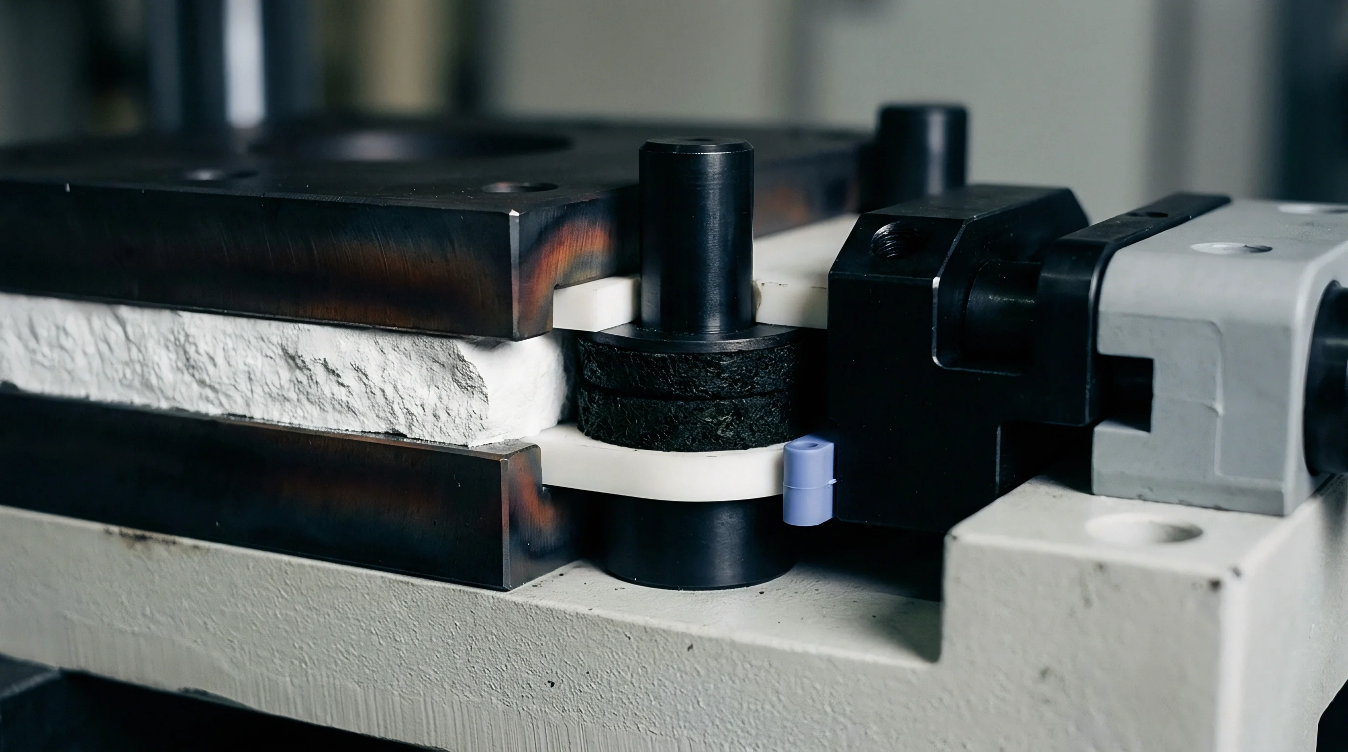
Time-dependent strain progression under sustained cyclic clamping pressure alters shutoff dimensions across extended injection molding production schedules. While initial micro hobbing occurs during early press setup cycles through primary plastic yield, shutoff lands continue to deform slowly across hundreds of thousands of press cycles. High operational temperatures accelerate this prolonged plastic strain progression, inducing steady dimensional loss on primary sealing faces.
Heterogeneous insert assemblies operate under conditions conducive to localized thermal deformation. Tooling materials subjected to continuous compressive stress at elevated fractions of their melting points exhibit measurable time-dependent strain. High clamp forces held over long hold times promote atomic diffusion and dislocation movement within metallic crystalline structures.
How Does Cyclic Heat Drive Deformation across Shutoff Boundaries?
Cyclic mechanical loading combined with oscillating thermal profiles intensifies localized material displacement over time. Every injection cycle delivers a thermal shock as molten plastic contacts shutoff surfaces, raising local skin temperatures by forty to eighty degrees Celsius for brief intervals. Elevated peak skin temperatures temporarily drop material yield limits at the exact moment cavity pressure drives melt against shutoff edges.
Simultaneously, machine clamp systems pulse stress across insert land faces once per cycle. This combination of thermal spikes and cyclic pressure pulses accelerates strain accumulation far beyond steady-state creep predictions. Materials that appear stable under static laboratory testing experience steady micro hobbing creep when subjected to real press operational cadences.
| Material Pairing | Applied Stress (MPa) | Interface Temp (°C) | Recession at 100k Cycles (µm) | Recession at 1M Cycles (µm) |
|---|---|---|---|---|
| CPM 10V vs H13 | 1,100 | 140 | 0.6 | 1.4 |
| Tungsten Carbide vs CPM 10V | 1,400 | 140 | 0.3 | 0.8 |
| Moldmax HH vs H13 | 600 | 160 | 2.1 | 5.8 |
| Elmax vs Moldmax HH | 750 | 160 | 1.8 | 4.9 |
| Data based on FEA constitutive models verified by white-light profilometry across standard shutoff geometry. | ||||
Mathematical modeling of micro hobbing rates requires non-linear strain equations incorporating temperature and strain-rate sensitivity parameters. Standard Anand or Johnson-Cook constitutive stress-strain models allow engineers to calculate plastic strain increments generated per cycle. Accumulating these micro-strain increments across extended production timelines yields accurate predictions of total shutoff land recession.
Hard inserts embedded within softer tool steel cavity plates require land stress calculations based on the yield strength of the softer backing material at peak operating temperature.
Long-term dimensional stability requires maintaining peak shutoff contact stress well below the creep initiation limit for the softer material in the assembly. Plastic strain accumulation slows down as shutoff faces broaden through indentation, expanding total contact area and dropping nominal stress. Slower strain rates eventual reach a temporary plateau, yet ongoing thermal cycling ensures total deformation never fully ceases over production lifespans.
Temperature-Dependent Strain Progression
Operating temperatures dictate the velocity of plastic displacement across shutoff interfaces. Beryllium-copper alloys begin exhibiting time-dependent compressive strain at temperatures as low as one hundred twenty degrees Celsius when sustained stresses exceed four hundred megapascals. Tool steel alloys like H13 resist creep at lower temperatures but lose resistance rapidly once core temperatures surpass two hundred degrees Celsius.
Thermal modeling must account for localized heat accumulation in tight core inserts with restricted cooling access. Insufficient heat dissipation elevates steady-state insert temperatures far above main mold base measurements. High core temperatures accelerate local creep rates, causing unexpected shutoff recession on isolated insert details while surrounding parting line surfaces remain stable.
Designing shutoff land areas to balance clamp tonnage over the softest structural component in the insert stack preserves core geometry across long production runs.
Imprint
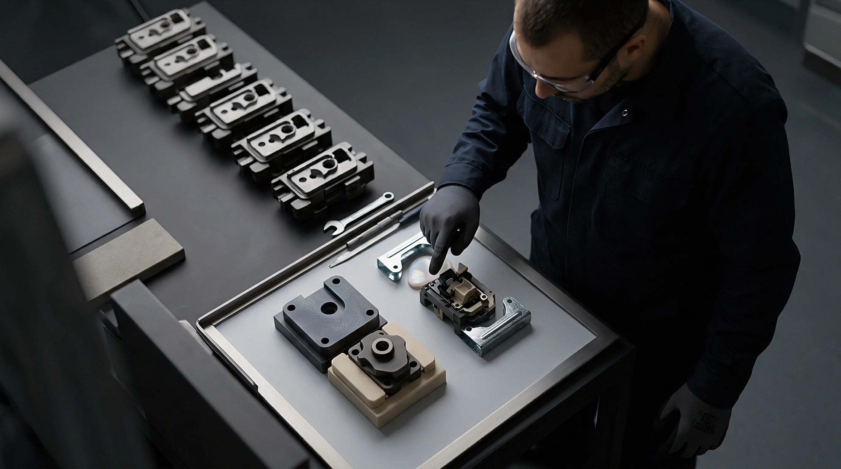
Physical measurement of localized surface recessions requires nanometer-scale optical equipment capable of scanning multi-material parting lines without damaging polished shutoffs. Conventional mechanical stylus tools lack the spatial resolution and vertical sensitivity needed to map micro hobbing depths on complex insert geometries. White-light interferometry and confocal laser scanning microscopy provide non-contact three-dimensional topography scans required to document surface deformation profiles accurately.
Quantifying micro hobbing involves establishing clean reference datums on uncontacted regions adjacent to shutoff lands. Optical metrology systems measure relative height differentials across material boundaries, differentiating between absolute plastic indentation and general mold base wear. Scanning identical shutoff locations at fixed cycle intervals yields precise material loss curves over time.
Optical Profilometry Inspection Protocol
Executing accurate metrology scans on multi-material assemblies demands strict environmental control and surface preparation protocols. Contamination or temperature variations distort nanometer-level measurements, masking early-stage plastic deformation trends.
- Clean the parting line faces with anhydrous isopropyl alcohol to eliminate oil film residues.
- Mount the core insert in a thermal stabilization fixture held at twenty degrees Celsius for two hours.
- Execute a three-dimensional white-light interferometry scan across the shutoff boundary land at half-micrometer vertical resolution.
- Extract height profiles orthogonal to the shutoff edge to measure step depth relative to the uncontacted reference datum.
Scanning both sides of a shutoff pairing reveals the distribution of plastic deformation between mating components. Comparing measured physical imprints against non-linear finite element contact simulations validates material constitutive models, improving future shutoff design calculations.
Worked Calculation of Micro Hobbing Depth
Calculating expected micro hobbing depth requires combining elastic contact mechanics with plastic yield formulations. Consider a heterogeneous shutoff assembly where a hardened powder-metal core insert (CPM 10V, 60 HRC) mates against a tool steel cavity plate (AISI H13, 46 HRC). The nominal shutoff land width sits at 0.8 millimeters, and total press clamping force generates a nominal contact pressure Pnom of 1,250 MPa across the shutoff area.
The operating temperature at the shutoff land reaches 160°C during steady-state molding. At this temperature, the compressive yield strength σy(T) of the H13 cavity steel drops to 1,080 MPa, while CPM 10V holds a yield strength of 2,200 MPa. Because nominal contact pressure exceeds the high-temperature yield limit of H13, plastic deformation occurs exclusively within the H13 mating surface.
Plastic displacement δp per cycle is calculated using a modified linear plastic hardening strain model:
δp = w · left( fracPnom – σy(T)Hp right)
Where w represents land width (0.8 mm or 800 µm), and Hp represents the plastic hardening modulus of H13 steel at 160°C (approximately 45,000 MPa). Substituting values yields:
δp = 800 · left( frac1,250 – 1,08045,000 right) = 800 · left( frac17045,000 right) ≈ 3.02 µm
This single-cycle plastic strain calculation establishes initial micro hobbing depth during tool commissioning. Accumulated cyclic strain over 500,000 production cycles under thermal fatigue increases total shutoff recession to approximately 4.8 micrometers as work hardening stabilizes local deformation.
Toolmakers frequently claim that observed shutoff recessions stem entirely from improper press clamp calibration rather than inadequate steel hardness selection.


Preload
Establishing calculated initial mechanical compression across insert assemblies balances thermal expansion gains against plastic deformation losses during hot press operation. Tool designers utilize structural shims or ground stand-off lands to impose controlled interference on core inserts during mold assembly. Correct interference ensures tight sealing contact during production without generating destructive peak stresses.
Calculating insert stack interference demands accounting for every component in the mechanical load path. Small manufacturing tolerances across insert pocket depths, shim thicknesses, and core retainer plates stack up rapidly. Uncontrolled tolerance stack-ups easily double intended shutoff preloads, driving instant severe micro hobbing during first mold heat-up trials.
- Thermal expansion matching prevents excessive compressive stress build-up when core inserts reach steady-state molding temperatures.
- Substrate hardness verification guarantees that backing plates support high-alloy insert blocks without experiencing permanent pocket depression.
- Land area scaling balances machine clamp tonnage across all shutoff faces to maintain contact stress below fifty percent of elevated-temperature yield limits.
Preload controls initial contact. High-precision tooling practices rely on spring-loaded or hydraulic floating shutoff inserts to maintain uniform contact force across fluctuating thermal conditions. Floating designs eliminate rigid mechanical stops, protecting delicate heterogeneous material interfaces from thermal expansion overload.
Compliance with DIN 16742 plastic molding tolerance classes requires shutoff land depth variations to remain within five micrometers over total production lifespans.
Incorporate flexible design elements whenever brittle materials like tungsten carbide mate against tool steel mold bases. Dynamic compensation mechanisms preserve seal integrity while isolating fragile core components from destructive stress concentrations caused by mold plate deflection under full press clamping loads.
Stack Height Interference Calculation
Determining optimum insert stack protrusion requires precise thermal-mechanical stress analysis. Structural engineers calculate room-temperature stack height interference by subtracting differential thermal growth values from target hot shutoff compression figures.
A copper-alloy insert expanding two hundredths of a millimeter beyond its steel pocket wall requires a corresponding room-temperature height reduction. Setting stack height equal to or slightly below cavity plate faces when cold ensures that thermal expansion achieves perfect flush sealing alignment once the tool reaches stable molding temperatures.
Material Selection Guidelines for Heterogeneous Shutoffs
Material selections determine long-term parting line durability. Pairing materials with similar thermal expansion coefficients reduces interfacial sliding friction and localized shear failure rates. When thermophysical material properties diverge sharply, mechanical retention designs must allow controlled lateral expansion.
Backing plate hardness must equal or exceed core insert hardness to prevent secondary micro hobbing into insert pocket floors. A hard CPM 10V insert supported by a soft 28 HRC mold base plate drives down into its pocket under clamping force, causing the entire insert assembly to recede without experiencing direct shutoff land yielding.
Incorporating DIN 16742 tolerance class TG3 requirements into tooling supply contracts forces tool shops to guarantee insert stack dimensional integrity under thermal load before final payment release.
Reserve
Tooling life prediction models incorporate thermal softening and micro-indentation rates to establish commercial refurbishment cycles for multi-material core components. Tooling assets degrade predictably under cyclic thermal and mechanical stresses. Advanced capital management strategies calculate structural wear reserves, budgeting scheduled insert re-grinding or replacement intervals well before shutoff deterioration causes plastic part quality rejections.
Financial projections must account for accelerated wear cycles on high-conductivity or ultra-hard core inserts. Sourcing practice protocols demand establishing detailed maintenance reserve funds based on verified micro hobbing depth predictions. A tool running high-volume technical components requires insert re-lapping procedures once shutoff land recession reaches three to five micrometers.
Preventive re-grinding of shutoff insert faces restores original sealing geometry before plastic flash damages expensive cavity steel.
Refurbishment costs represent a small fraction of total mold acquisition pricing when scheduled proactively. Neglecting micro hobbing progression leads to flash contamination along sliding core mechanisms, causing catastrophic mold jams that destroy complete cavity blocks. Proactive insert stack management preserves core tooling equity and maintains stable unit manufacturing costs over multi-year production campaigns.

Amortization Mechanics for High-Wear Cavities
Capital amortization calculations distribute initial tooling costs and expected maintenance expense over total projected part volumes. Insert assemblies subject to severe micro hobbing require higher maintenance reserves per thousand molded parts. Identifying high-wear material shutoffs early allows financial planners to build realistic tooling maintenance line items into piece-price quotes.
Modular insert construction minimizes long-term repair expenditure. Designing shutoff lands on small, easily replaceable insert sub-assemblies isolates wear zones, allowing rapid toolroom replacement without re-machining primary cavity blocks. Modular designs lower refurbishment downtime from weeks to hours, protecting production schedules.

Tooling Maintenance Financial Projections
Comprehensive tooling maintenance budgets incorporate spare insert manufacturing runs during initial tool construction. Producing replacement shutoff inserts alongside primary tooling components reduces individual unit costs by fifty to seventy percent compared to custom emergency fabrication runs during production outages.
Factoring micro-hobbing recession rates into tooling maintenance budgets enables precise calculation of spare insert quantities needed to maintain target part production schedules.