Angled Tooling Shut off Clearances in Injection Moulding
Angled shut-offs require minimum seven-degree draft, differential metallurgy, and stop-pad pre-loads to seal within eighty percent of resin flash thresholds.


Contact
Shut-off surfaces oriented between three and forty-five degrees from the tool draw direction require deliberate mechanical separation before mould clamp tonnage fully locks the tool. An unvented perpendicular landing absorbs parting force across its primary face. An angled mating plane transforms that clamping energy into a lateral wedging vector, driving sliding components outward, scuffing core inserts, and shearing thin feather-edges within a few thousand cycles.
Tool shops routinely receive part CAD displaying through-holes or snap latches modelled with parallel sidewalls. A toolmaker translates these features into bypass cores, sliding splits, or lifters that must seal molten resin at high injection pressures without galling tool steel.
Every angled shut-off balances two physical boundaries: the resin flash threshold and the mechanical clearance needed to prevent galling during tool closure. Unfilled semi-crystalline polymers such as polypropylene, polyamide 66, and polyoxymethylene flow into gaps wider than 0.010 millimetres to 0.020 millimetres under packing pressures between 60 and 120 megapascals. Highly viscous or glass-filled engineering resins tolerate shut-off boundaries between 0.030 millimetres and 0.050 millimetres before material flashes.
When a tool closes, thermal expansion differentials between cavity inserts and base plates alter these theoretical gaps. A moving core component requires physical clearance to travel without sliding contact until the final fraction of a millimetre of stroke.
The allowable shut-off gap equals eighty percent of the resin flash threshold under maximum peak cavity pressure.
The parting line geometry dictates the required angle. Where part geometry permits, tooling engineers specify draft angles of seven degrees or greater on bypass shut-offs. At seven degrees, two opposing steel faces approach with adequate clearance during the clamping stroke, touching only during the final 0.05 millimetres of platen travel.
When part constraints force a shut-off angle down to three degrees, the clearance window narrows drastically. The closing stroke drags opposing steel faces across one another through twenty times the contact length of a steeper angle. This friction accelerates abrasive wear, strips protective surface treatments, and produces parted flashing on production mouldings.


Draft
Draft angles determine the rate of steel clearance per unit of platen motion. As the moving platen travels along the clamp stroke, an angled core insert approaches its stationary cavity pocket along a closing vector. The mechanical air gap separating the two steel faces changes as the sine of the shut-off angle multiplied by the remaining stroke distance.

Trigonometric Clearance across the Stroke
Small angles compromise mechanical clearance during tool assembly and press motion. At a three-degree angle, a platen positioned 0.100 millimetres from full closure leaves a perpendicular gap between shut-off faces of only 0.005 millimetres. That distance sits well inside typical press platen kinematic misalignment, which frequently runs between 0.010 millimetres and 0.030 millimetres on toggle or hydraulic machines.
The faces touch prematurely. At seven degrees, that same 0.100-millimetre stroke position provides an air gap of 0.012 millimetres. At ten degrees, the air gap widens to 0.017 millimetres.
Draft choices translate directly into allowable manufacturing tolerances for CNC milling, wire EDM, and surface grinding. Tight draft angles force the toolroom to execute micro-inch surface finishes and hold dimensional stack-ups within 0.005 millimetres across entire insert banks. Generous draft angles relax these manufacturing limits, permitting stable parting planes that seal effectively over hundreds of thousands of press cycles.
| Shut-off Angle (deg) | Gap at 0.50 mm Stroke (mm) | Gap at 0.10 mm Stroke (mm) | Gap at 0.05 mm Stroke (mm) | Friction Travel Length (mm) |
|---|---|---|---|---|
| 3 | 0.026 | 0.005 | 0.002 | 0.95 |
| 5 | 0.043 | 0.008 | 0.004 | 0.57 |
| 7 | 0.061 | 0.012 | 0.006 | 0.41 |
| 10 | 0.087 | 0.017 | 0.009 | 0.29 |
| 15 | 0.129 | 0.026 | 0.013 | 0.19 |
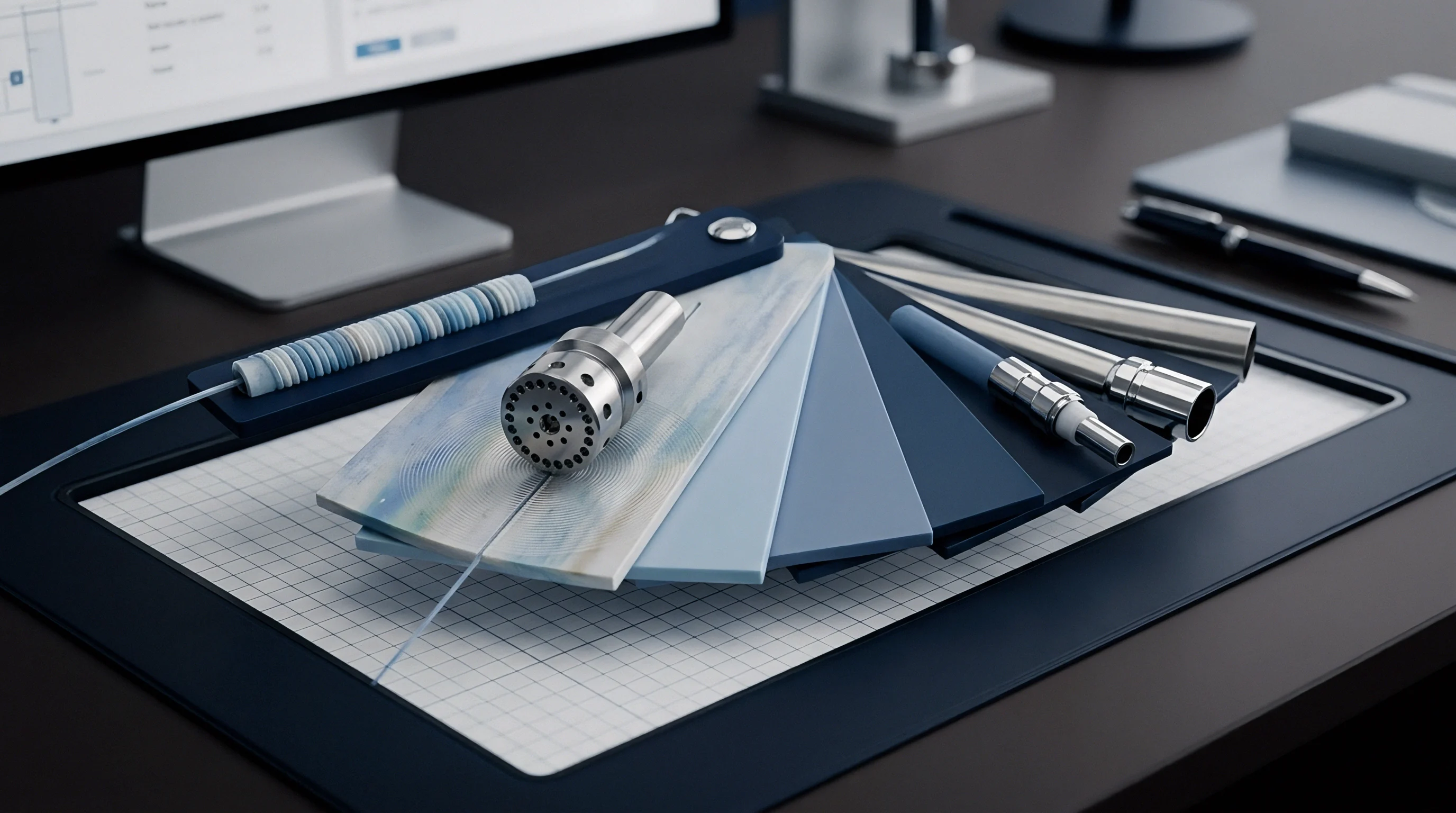
Part Geometry Realities
Product designers regularly request zero-draft windows to accommodate functional latches, PCB card guides, or fluid ports. Meeting zero-draft requests on an internal through-hole requires bypassing core blades that rub against each other along the split line. To avoid catastrophic galling, the toolmaker steps the parting line down the center of the aperture, creating two opposing shut-off faces that angle toward each other.
A part wall displaying a continuous through-hole incorporates an angled shut-off that terminates on an opposing core blade. The intersection leaves a faint witnessing line across the plastic component. Where space permits, positioning a five-degree bypass angle inside the part aperture preserves functional perpendicularity on external part walls while providing acceptable clearance for the closing steel.
Neglecting draft on angled faces shifts parting loads onto alignment leader pins. Standard tool design isolates guidance mechanisms from cavity sealing surfaces. Guide pins position the mould halves before cavity inserts engage; interlocks provide secondary registry; angled shut-offs execute the final seal.
Forcing an angled shut-off to act as an alignment guide generates heavy micro-fretting and uneven cavity pressure distribution.


Steel
Cavity steel grades dictate resistance to edge rolling, adhesive pick-up, and fatigue cracking along high-pressure shut-off boundaries. Toolmakers select alloys balancing compressive yield strength, core toughness, and compatibility with surface hardening treatments. A baseline pre-hardened P20 steel, treated to 30 HRC, exhibits adequate machinability but lacks the yield strength needed to resist edge deformation on angled shut-offs subjected to repeated cycle tonnages.

Alloy Properties under Cyclic Clamping
High-volume production tools run premium grades such as AISI H13, 420 stainless steel, or Bohler M333. Hardened to 48 through 54 HRC, through-hardened tool steels resist the mechanical mushrooming that plagues softer tool metals on thin bypass cores. The compressive yield strength of through-hardened H13 reaches roughly 1650 megapascals at room temperature.
This strength provides a wide safety buffer against local yield under intense tonnage concentrations.
Corrosive resins such as polyvinyl chloride or flame-retardant polymers outgassing halogenated compounds demand high-chromium stainless grades like AISI 420 or DIN 1.2083. Chemical attack erodes the pristine sharp edges of a shut-off boundary, effectively opening the parting gap and encouraging plastic flash. Surface degradation accelerates when condensation forms on cold tool inserts running chilled water below twelve degrees Celsius.
Tooling life drops by half whenever moving shut-off faces share identical metallurgy and surface hardness without lubrication or coating.
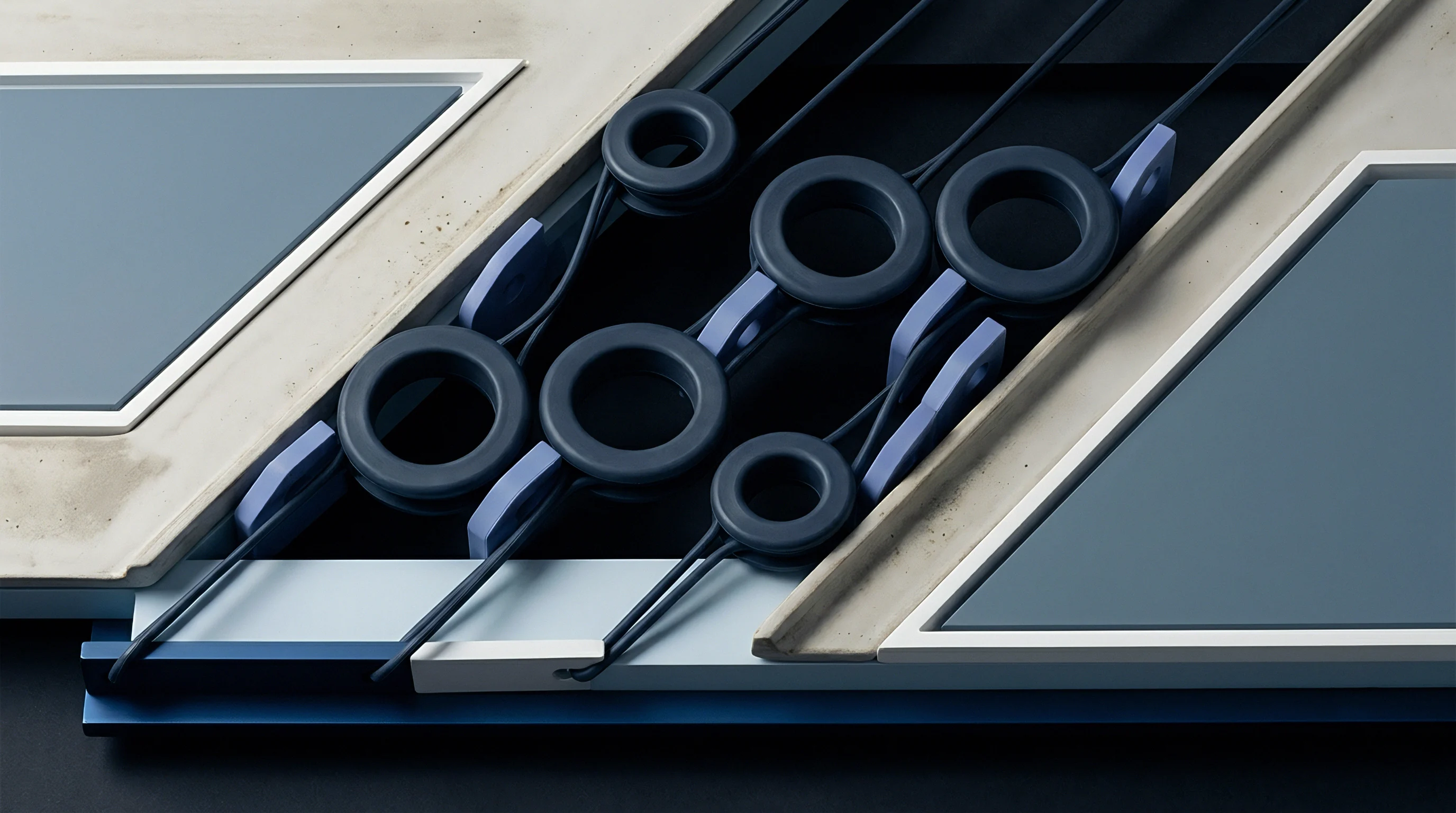
Hardness Differentials and Galling Resistance
Adhesive wear occurs when identical metals slide against each other under boundary pressure. The crystal lattices bond momentarily and tear away microscopic fragments of the base steel. A standard toolmaking rule introduces a hardness spread between opposing shut-off elements.
The stationary cavity insert might be through-hardened to 52 HRC, while the moving core blade or slide face runs at 56 HRC.
Dissimilar metals mitigate this wear pattern entirely. Beryllium-copper alloys such as MoldMAX or Ampco 18 bronze wear plates are paired with hardened tool steel components. Bronze components incorporate graphite plugs to sustain sliding lubrication inside cleanroom moulding environments where external greases contaminate medical or optical parts.
The differing atomic structures prevent microscopic friction welding during slide entry.

Surface Treatments and Friction Modifiers
Modern tooling operations use physical vapor deposition coatings to extend tooling longevity. Titanium carbo-nitride, chromium nitride, and diamond-like carbon coatings produce hard, low-friction surface layers between two and four micrometres thick. Diamond-like carbon exhibits a friction coefficient below 0.15 against dry steel, eliminating the need for particulate-generating grease on slide components.
Nitriding treatments provide a high-hardness case layer without altering the core ductility of pre-hardened steels. Gas or plasma nitriding elevates the surface hardness of an angled shut-off component to over 65 HRC up to a depth of 0.10 millimetres. Nitrided layers run brittle along razor-thin feather edges; toolmakers grind a microscopic land onto sharp bypass corners before nitriding to prevent brittle chipping under clamp impact.
A supplier often claims that an advanced physical vapor deposition coating allows zero-draft shut-offs to run indefinitely without steel clearance or preventative maintenance.


Fit
Toolroom benching settles the real operational contact between angled shut-off components. Theoretical CAD geometry provides the basic dimensions, but precision EDM and CNC grinding leave micro-inch variances across multi-cavity layouts. Skilled mouldmakers spot the tool halves using Prussian blue transfer dye to verify contact patterns before the tool mounts in a press.

The Prussian Blue Spotting Protocol
Verification of shut-off sealing relies on systematic transfer dye testing within a spotting press. A technician spreads an ultra-thin film of oil-based blue dye across the stationary cavity shut-off lands. The moving tool half closes under minimal hydraulic pressure until initial steel contact registers.
- Prussian blue application transfers an unbroken color film measuring less than 0.005 millimetres thick onto clean, degreased shut-off surfaces.
- Low-tonnage closure brings the mould halves together inside a spotting press at roughly five to ten percent of normal operating clamp tonnage.
- Pattern inspection reveals contact zones, indicating high spots that carry disproportionate clamp force and low areas where gaps remain.
- Manual stoning refines high contact spots with fine-grit abrasive stones to level the parting lands across the entire insert nest.
- Final re-spotting confirms an eighty-five percent contact area across all primary angled shut-offs while maintaining specified parting land drop-offs.

Land Dimensions and Step Relief
Angled shut-offs do not seal across their entire surface length. Toolmakers build a sealing land measuring 1.5 millimetres to 3.0 millimetres in width directly adjacent to the moulding cavity. Beyond this sealing boundary, the tool relief drops back between 0.50 millimetres and 1.00 millimetres.
Relieving the non-functional steel reduces the required spotting surface area and prevents tool clamp force from dispersing over unnecessary metal mass.
Step reliefs prevent catastrophic tool crush caused by small parting line contaminants. An un-relieved tool face traps plastic crumbs or degraded resin flake, concentrating hundreds of tons of machine clamp pressure onto an isolated spot. Relieving adjacent non-critical surfaces creates debris collection pockets, safeguarding the delicate shut-off edge from unexpected mechanical overload.
The transition between the primary shut-off land and the relieved pocket requires smooth blended transitions. Sharp internal corners generated by plunge EDM introduce notch stress risers that fracture under high-frequency clamping impacts. Tool drawings must include generous transition radii to distribute mechanical load into the underlying core backing block.


Heat
Thermal expansion alters tooling dimensions throughout the moulding cycle. A tool measured and spotted at an ambient shop temperature of twenty degrees Celsius changes substantially when oil or pressurized water circuits heat the steel inserts to operating temperatures between 80 and 140 degrees Celsius. The dimensional changes directly compress or widen angled shut-off clearances.

Differential Expansion Mechanics
Linear thermal expansion follows the predictable thermodynamic coefficient of the specific metal alloy. Standard carbon and tool steels expand at roughly eleven to thirteen micrometres per metre per degree Celsius. When cavity inserts run hotter than the surrounding mould chase, the inserts grow outward.
This expansion forces angled shut-off faces closer together, converting a planned running clearance into interference contact.
Aluminum mould inserts present severe thermal challenges when paired with steel base structures. Aluminum exhibits a thermal expansion coefficient exceeding twenty-two micrometres per metre per degree Celsius, nearly double that of steel. An aluminum core insert operated without thermal clearance will shear its angled shut-off faces against an opposing P20 cavity pocket as soon as the tool attains steady-state cycling temperatures.
| Tool Material | Expansion Coeff. (μm/m-°C) | Insert Length (mm) | ΔT from Ambient (°C) | Linear Growth (mm) |
|---|---|---|---|---|
| AISI P20 Steel | 12.0 | 150.0 | 60.0 | 0.108 |
| AISI H13 Tool Steel | 11.5 | 150.0 | 80.0 | 0.138 |
| DIN 1.2083 Stainless | 10.5 | 150.0 | 60.0 | 0.095 |
| MoldMAX BeCu | 17.0 | 150.0 | 40.0 | 0.102 |
| QC-10 Aluminum | 23.0 | 150.0 | 40.0 | 0.138 |

Conformal Cooling and Core Blade Thermal Gradients
Bypass shut-off cores often take the form of tall, narrow steel blades protruding deep into the plastic part cavity. These blades absorb heat directly from the surrounding polymer melt but lack internal volume for standard cross-drilled cooling channels. Without active cooling, core blades run twenty to fifty degrees Celsius hotter than the main cavity block.
Thermal gradients cause uneven expansion along the height of the core blade. The tip of the blade grows wider than its base, changing the intended shut-off angle and generating localized interference at the apex of the closing wedge. Implementing direct bubblers, thermal pins, or additive manufacturing with conformal cooling channels balances core blade temperatures and maintains consistent shut-off geometry across long production shifts.
Cooling circuit placement must provide uniform heat extraction across both sides of an angled shut-off interface. When the core insert runs colder than the cavity insert, the angled core shrinks away from the shut-off land, opening an unintended gap. The resulting clearance breach allows pressurized melt to penetrate the gap and form flash along the part edge.
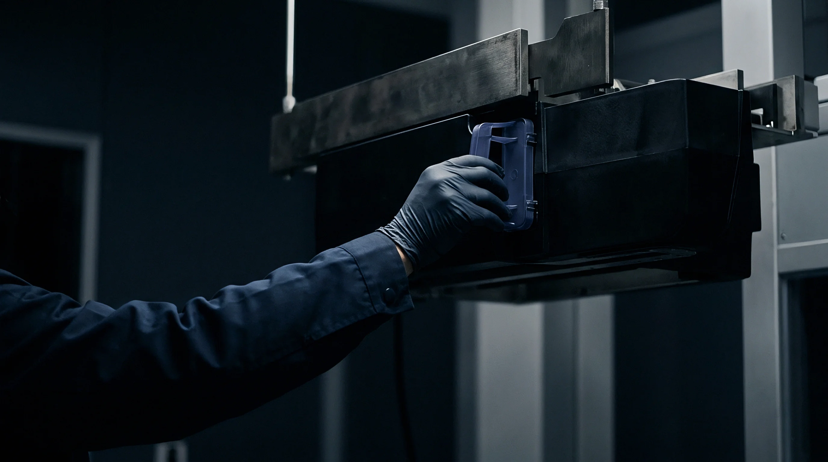

Flash
Flashing occurs when molten polymer overcomes the resistance of the shut-off boundary and escapes along the parting line. The physical mechanism combines polymer melt rheology, injection velocity, holding pressure, and instantaneous steel deflection. Understanding resin-specific flash boundaries enables tooling engineers to define safe shut-off clearances that prevent cosmetic defects and binding during ejection.
Polymer Viscosity and Sealing Boundaries
Thermoplastic resins exhibit varied flow properties under injection processing conditions. Unfilled crystalline resins exhibit low melt viscosities, particularly under high shear rates within the gate and runner system. Amorphous resins like polycarbonate or ABS possess stiffer molecular structures, yielding higher melt viscosities that resist penetration into micro-fine gaps.
- Liquid crystalline polymer flashes into gaps exceeding 0.008 millimetres, demanding diamond-ground shut-off lands and precision guided tool components.
- Unfilled polyamide resins penetrate gaps wider than 0.012 millimetres at standard processing melt temperatures and moderate packing pressures.
- Polypropylene grades flow into gaps beyond 0.018 millimetres, requiring rigid tool clamping and uniform cavity pre-loading.
- High impact polystyrene resists flashing up to gaps of 0.030 millimetres, providing wider manufacturing windows for complex sliding cores.
- Glass filled polycarbonate tolerates clearances up to 0.045 millimetres without edge penetration due to high bulk melt viscosity and fiber bridging.

Pressure Drops across the Sealing Land
The length of the shut-off land functions as a flow restrictor. Molten resin entering a narrow clearance experiences rapid shear thinning and chilling against the cold tool steel walls. If the land length measures only 0.5 millimetres, the frozen layer cannot develop fast enough to arrest melt flow before it exits the parting plane as visible flash.
Extending the land length to 2.5 millimetres establishes sufficient flow resistance and thermal quench to freeze polymer runners before they penetrate the tool split.
Injection speed profiling controls pressure spikes at the moment of cavity fill. When the screw transfers from velocity-controlled filling to pressure-controlled packing, dynamic pressure peaks can flex tool plates. If an angled shut-off is positioned near the end of the fill path, switching transfer too late generates an inertia spike that separates the angled faces for several milliseconds, producing thick, stubborn flash.
Parting line flash thicker than 0.05 millimetres will permanently deform the steel shut-off lands under normal machine clamp tonnage.
Flash on an angled shut-off does not pull away cleanly during part ejection. Because the flash lies wedged along an angled plane, ejection forces drag the paper-thin plastic flap against the steel face. The trapped plastic fragments compress during the subsequent clamping stroke, indenting the tool steel and creating a permanent gap that worsens with every cycle.


Wear
Angled shut-offs deteriorate through three primary mechanical failure modes over high-volume production cycles. Adhesive galling, abrasive scouring from mineral or glass additives, and mechanical impact peening progressively alter interface dimensions. Detecting these wear modes early allows molders to schedule preventative refurbishments before parting surfaces suffer catastrophic damage.

Mechanical Galling and Impact Peening
Galling develops when unlubricated moving tool components experience boundary contact under pressure. Microscopic contact points weld momentarily, tearing metal away and creating torn, roughened grooves along the sliding plane. Left uncorrected, galling escalates rapidly, seizing slides and snapping internal core pins during mould opening.
Impact peening occurs on steep angled shut-offs when machine closing velocity is set too high during the mold protection phase. As the platens transition from low-pressure mould protection to high-pressure clamp lockup, the angled faces smash together. The repeated impact rolls the crisp edges of the shut-off land outward into the cavity space, forming a raised burr that scrapes parts during ejection.

Abrasive Wear from Reinforced Resins
Glass fibers, mineral fillers, and carbon nanotubes generate significant abrasive wear on cavity parting faces. As reinforced melt surges across the angled shut-off edge, exposed glass fibers act as miniature cutting tools, scouring away the base steel matrix. Over a run of two hundred thousand cycles, abrasive scoring washes out sharp shut-off edges, rounding a crisp 0.02-millimetre radius into a dull 0.20-millimetre curve.
Highly filled grades like fifty-percent glass-reinforced PA66 demand through-hardened powder-metallurgy tool steels such as Uddeholm Vanadis 4 Extra or Crucible CPM 1V. These alloys contain dense networks of hard vanadium carbides that resist fiber abrasion. Using conventional P20 steel with glass-filled resins leads to premature parting line wash-out and uncorrectable flash defects within weeks of production launch.
A standard manufacturing warranty clause often states that wear components, including angled shut-off inserts, are classified as routine consumables and must be replaced at the buyer’s expense once production exceeds two hundred and fifty thousand shots.


Limits
A rigorous economic calculation governs whether to execute an internal aperture using an angled bypass shut-off or a dedicated mechanical side-action slide. Angled shut-offs reduce initial tool build expenses and shorten cycling durations by eliminating moving mechanics. However, they expose the moulder to tighter process windows, faster tool wear, and scrap risks that can exceed initial cost savings.

Tooling Cost versus Mechanical Complexities
Building a fixed bypass shut-off into core and cavity inserts requires precise five-axis CNC machining, electrode EDM cutting, and hand benching. A comparable side-action slide demands dedicated wear plates, angle pins, heel lock blocks, gibs, and position sensors. A four-cavity tool incorporating eight fixed angled shut-offs costs roughly thirty percent less to build initially than a four-cavity tool requiring eight mechanical side actions.
The financial advantage shifts when factoring in production scrap and tool maintenance. A fixed angled shut-off operating with a steep five-degree bypass requires rebuilds every three hundred thousand cycles under continuous operation. A robust mechanical slide equipped with heel blocks and bronze wear plates routinely operates for more than one million shots before requiring refurbishment.
The tooling engineer balances upfront capital expenditure against long-term operational maintenance budgets.

Cycle Time Economics
Fixed angled shut-offs cycle faster than side-action mechanisms. A tool utilizing fixed cores opens and closes on a minimal platen stroke, ejecting parts on the fly without waiting for mechanical slides to retract or clear proximity sensors. A mechanical slide mechanism requires extended opening strokes to pull core pins clear of part undercuts, adding 0.8 to 2.5 seconds to the total cycle time.
On a high-volume consumer product running two million parts annually across a multi-cavity press, an additional 1.5 seconds of cycle time represents hundreds of machine hours. Machine-hour operational rates range from sixty to one hundred and fifty dollars per hour depending on machine tonnage. Squeezing seconds out of the cycle justifies the tighter process discipline and frequent benching maintenance required to keep fixed angled shut-offs running cleanly.

Which Tolerance Strategy Protects the Parting Land?
Protecting the integrity of an angled shut-off requires implementing pre-load interference blocks on primary tool parting lines. Toolmakers install hardened stop pads ground 0.025 millimetres to 0.050 millimetres taller than the cavity inserts. These stop pads absorb the primary machine clamp tonnage, preventing the angled shut-off faces from absorbing the full locking force of the injection press.
This design isolates the delicate angled lands, allowing them to kiss lightly under controlled contact pressure without carrying structural platen loads. The gap separating non-shut-off cavity surfaces must remain strictly consistent across the entire mould base. Proper tool pre-loading prevents platens from flexing and crushing insert corners, ensuring repeatable sealing through long production runs.
A tool setter might balance an out-of-spec angled shut-off by adding clamp tonnage to the machine, but this accelerates insert destruction without resolving the underlying dimensional issue.