Quantification Limits of Sub Micron Dynamic Expansion Errors in High Cavitation Micro Injection Tooling
Dynamic micro-tooling expansion limits sit at 0.3 micrometers, bounded by transient core heat spikes, clamp flexure, and interferometer sensor housing drift.

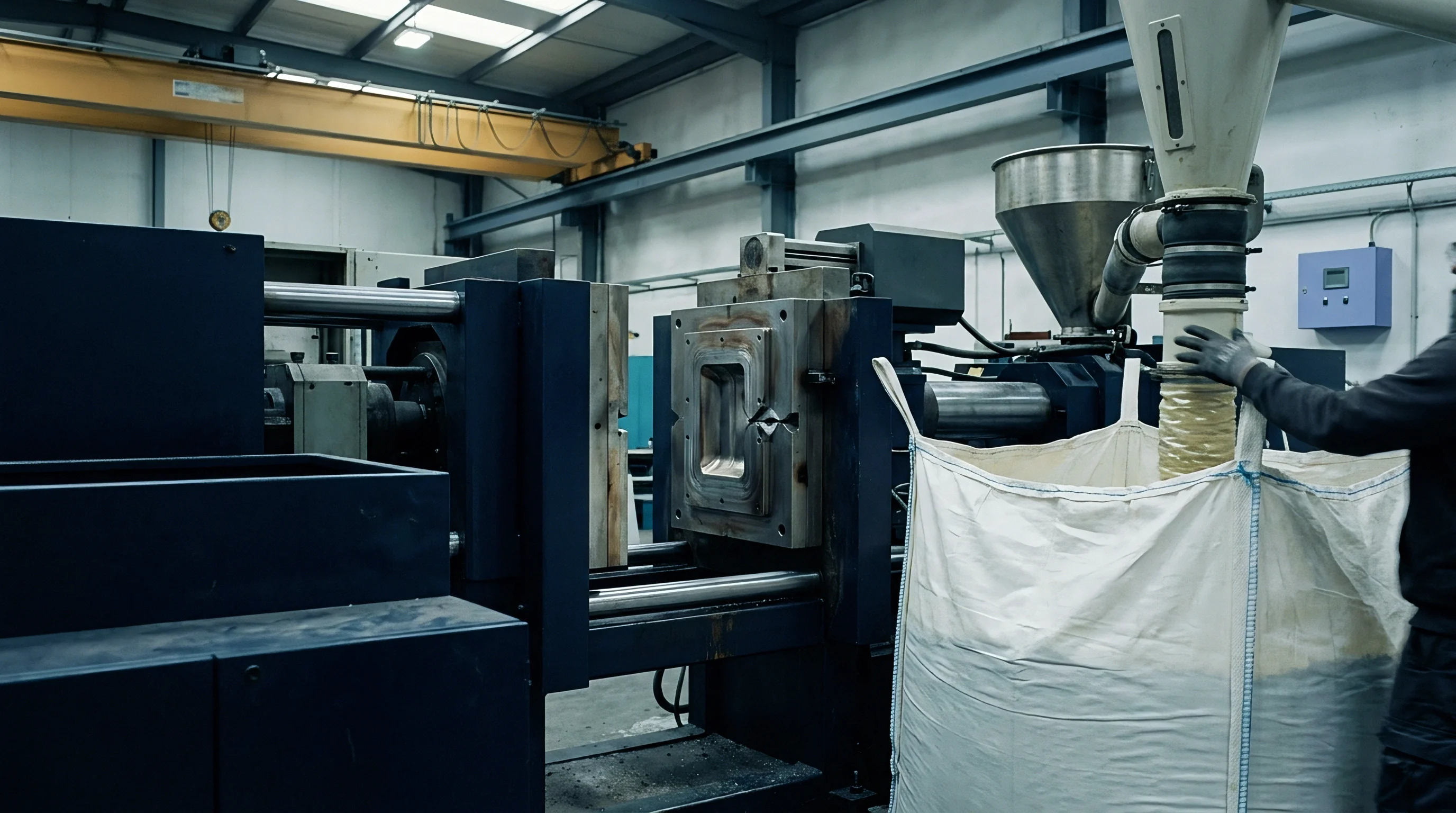
Steel
High-cavitation micro-injection tools taking sub-milligram shots depend on mold inserts staying dimensionally stable to within five hundred nanometers. During injection, heavy thermal loads create transient temperature gradients across core pins and cavity walls. Standard AISI 420 stainless steel has a thermal expansion coefficient of 10.6 micrometers per meter-Kelvin, whereas AISI H13 tool steel expands at 11.7 micrometers per meter-Kelvin.
A core pin one millimeter in diameter exposed to a localized twenty-degree Celsius temperature spike expands by over two hundred nanometers along its radial edge, shrinking nominal cavity volume and changing melt flow behavior before the gate freezes. Precision tooling design requires calculating these thermal expansion vectors explicitly.

Core Materials and Thermal Strain Boundaries
Tungsten carbide grades provide thermal expansion coefficients down to 4.5 micrometers per meter-Kelvin, holding dimensions steady under intense heat. Even so, tungsten carbide’s low fracture toughness restricts its use in fine features exposed to dynamic pressure shocks above one hundred fifty megapascals. Copper-beryllium alloys such as Ampcoloy deliver thermal conductivity up to two hundred forty Watts per meter-Kelvin, dissipating heat quickly but expanding at higher rates reaching 17.0 micrometers per meter-Kelvin.
Combining different tool steels across cavity plates and core inserts helps balance heat dissipation against differential thermal expansion stack-up.
| Alloy Grade | Coefficient of Thermal Expansion (10^-6 / K) | Thermal Conductivity (W / m K) | Elastic Modulus (GPa) | Sub-Micron Expansion Limit at Delta T = 15°C (nm / mm) |
|---|---|---|---|---|
| AISI 420 Stainless | 10.6 | 24.9 | 200 | 159.0 |
| AISI H13 Tool Steel | 11.7 | 28.6 | 210 | 175.5 |
| Tungsten Carbide (12% Co) | 4.5 | 80.0 | 580 | 67.5 |
| Ampcoloy 940 (CuBe) | 17.0 | 208.0 | 135 | 255.0 |

Mechanical Micromechanical Strain under Clamping Load
Hydraulic clamping force applied across a mold base compresses tool plates unevenly during production. A six-hundred-kilonewton clamp force on a two-hundred-millimeter tool base causes structural deflections between 0.15 and 0.45 micrometers at the outer mold boundaries. Core pins positioned near support pillars undergo compressive stress that shifts centerlines by three hundred nanometers relative to the parting line.
This uneven deflection between core inserts and mold plates alters part wall thickness across high-cavitation arrays. Ignoring localized steel compression and thermal expansion leads to chronic flash, cavity imbalance, and core fatigue failures within fifty thousand production cycles.


Pulse
Melt injection in micro-molding happens within fill times of fifteen to fifty milliseconds. Peak injection pressures reaching two hundred megapascals generate sharp stress waves that ripple through tool cavities with every shot. Transient heat transfer from molten engineering polymers such as polyetheretherketone at three hundred eighty degrees Celsius causes localized thermal expansion pulses along the outer skin of the core pins.

Transient Thermal and Mechanical Displacement Stack-Up
Consider a 32-cavity tool running liquid crystal polymer with a mold face temperature of three hundred thirty degrees Celsius, an injection duration of twenty-five milliseconds, a peak cavity pressure of one hundred twenty megapascals, and core pins made from AISI 420 stainless steel with an elastic modulus of two hundred GPa. During the twenty-five millisecond injection phase, heat conducts two hundred micrometers deep into the steel surface, creating a temporary surface layer expansion of 0.18 micrometers. Simultaneously, the hydraulic pressure wave flexes the core pin cantilever by 0.28 micrometers perpendicular to melt flow.
The combined transient displacement reaches 0.46 micrometers per cycle. Because this strain vanishes during cooling, post-molding measurements on a static coordinate measuring machine cannot register the dynamic breathing mechanism.
ISO 2768-m tolerance classifications fail to account for dynamic cavity expansion phenomena occurring during sub-fifty millisecond polymer injection phases.

Sequence for Dynamic Deflection Mapping
Flush-mounted piezoresistive transducer pins at cavity parting lines record real-time pressure peaks, while fiber-optic displacement sensors placed behind core inserts track axial movement during injection pulses. Synchronizing data acquisition with the press injection signal provides fine temporal resolution over millisecond windows. High-speed infrared thermal probes map surface temperature spikes along cavity walls to expose transient thermal gradients.
Summing transient thermal expansion vectors with pressure-driven mechanical flex yields the total dynamic displacement.
- Install piezoresistive transducer pins flush with cavity parting lines to record real-time dynamic pressure peaks.
- Position fiber-optic displacement sensors behind core inserts to measure mechanical axial displacement during injection pulses.
- Synchronize data acquisition channels with the press injection signal at sampling frequencies exceeding ten kilohertz.
- Map temperature spikes along cavity walls using high-speed infrared thermal probes during un-clamped dry cycles.
- Calculate total dynamic expansion by summing transient thermal growth vectors with pressure-induced mechanical deflections.
Toolmakers often attribute sub-micron dimensional variation to inconsistent resin shrinkage instead of recognizing the transient dynamic breathing of cavity plates under injection pressure.


Gauge
Measuring sub-micron metal movements inside an operational mold presents severe physical challenges. Contact linear variable differential transformers lack the response speed needed to capture twenty-millisecond pressure pulses, while cavity-wall piezoresistive sensors suffer from thermal drift under wide temperature swings. Non-contact optical methods like laser Doppler vibrometry and white-light interferometry require direct line of sight to inner tool surfaces, which polymer obstructs once injection begins.

Will Optical Metrology Resolve Dynamic Cavity Breathing below Five Hundred Nanometers?
Fiber-optic Fabry-Perot interferometers positioned behind cavity inserts measure displacements down to ten nanometers at high acquisition rates by tracking changes in optical path length within the micro-cavity gap between sensor tip and core pin. Over extended production runs, however, thermal expansion of the sensor housing introduces phantom signals ranging from fifty to two hundred nanometers. Isolating true core displacement from housing expansion requires real-time thermal compensation driven by concurrent localized temperature readings.
Fiber-optic interferometric sensors detect mold plate displacements of twelve nanometers under thermal equilibrium at one hundred forty degrees Celsius.
| Sensor Technology | Spatial Resolution (nm) | Sampling Frequency (kHz) | Operating Temp Limit (°C) | Thermal Drift Sensitivity (nm / °C) |
|---|---|---|---|---|
| Fiber-Optic Fabry-Perot | 10 | 50 | 200 | 8.5 |
| Piezoresistive Pin | 100 | 20 | 160 | 22.0 |
| Capacitive Displacement | 25 | 100 | 120 | 45.0 |
| Laser Doppler Vibrometer | 5 | 250 | 300 | 1.2 |

Sensor Performance and Signal Interference Modes
In-cavity sensing systems face harsh conditions during high-volume production. Cyclic high pressures compress optical fibers, inducing birefringence effects that corrupt interference fringe analysis. Electrical noise from press servo motors introduces high-frequency harmonics into raw capacitive displacement signals.
- Thermal Sensitivity Drift skews output signals as temperature swings expand housing dimensions during continuous thermal cycling.
- Mechanical Cable Strain degrades high-frequency signals when mold-opening vibrations induce micro-flexure in signal cabling.
- Polymer Outgassing Deposition coats optical windows, reducing signal intensity and distorting interference fringe profiles.
- Platen Vibration Interference superimposes low-frequency machine noise onto micro-meter displacement waveforms during clamping sequences.
Whether non-invasive optical arrays can reliably isolate sub-hundred-nanometer dynamic cavity breathing from machine vibration across extended manufacturing shifts remains unproven.


Matrix
High-cavitation tooling distributes polymer melt through complex manifold systems to dozens or hundreds of individual cavities. Heat distribution across a sixty-four-cavity mold base is inherently non-uniform, as hot runner nozzles transfer localized thermal loads to nearby cavity plates and create radial thermal gradients across the mold layout.

Thermal Gradients across Large Cavitation Grids
Inserts located near hot runner nozzles run at temperatures up to four degrees Celsius higher than positions near the outer edges. In an AISI 420 steel mold base measuring three hundred millimeters across, a four-degree gradient causes 12.7 micrometers of differential expansion between extreme cavity positions. This thermal imbalance creates uneven shut-off pressure along the parting line: inner cavities suffer heavy compression and wear, while outer cavities can separate slightly during injection, causing microscopic flash.
Thermal equilibrium across high-cavitation mold bases requires active multi-zone oil tempering circuits running continuous turbulent flow.

Tooling Architecture Checklist for Multi-Cavity Balance
Designing balanced feed systems reduces pressure variations across active cavities, while isolating individual core blocks limits stress transmission through the tool plates.
- Symmetric Runner Geometry balances melt transit time and shear heating uniformly across every cavity path in the mold matrix.
- Independent Cooling Loops regulate thermal distribution across inner and outer cavity groups to suppress radial thermal gradients.
- Floating Cavity Inserts isolate individual cores from mold base thermal expansion through calibrated expansion gaps.
- Guided Ejection Plates maintain centerline alignment between upper and lower cavity blocks during continuous thermal expansion cycles.
Standard procurement agreements specifying cavity interchangeability under DIN 16742 Grade TG3 explicitly state that thermal expansion verification must occur across all active cavities at maximum production mold operating temperatures.

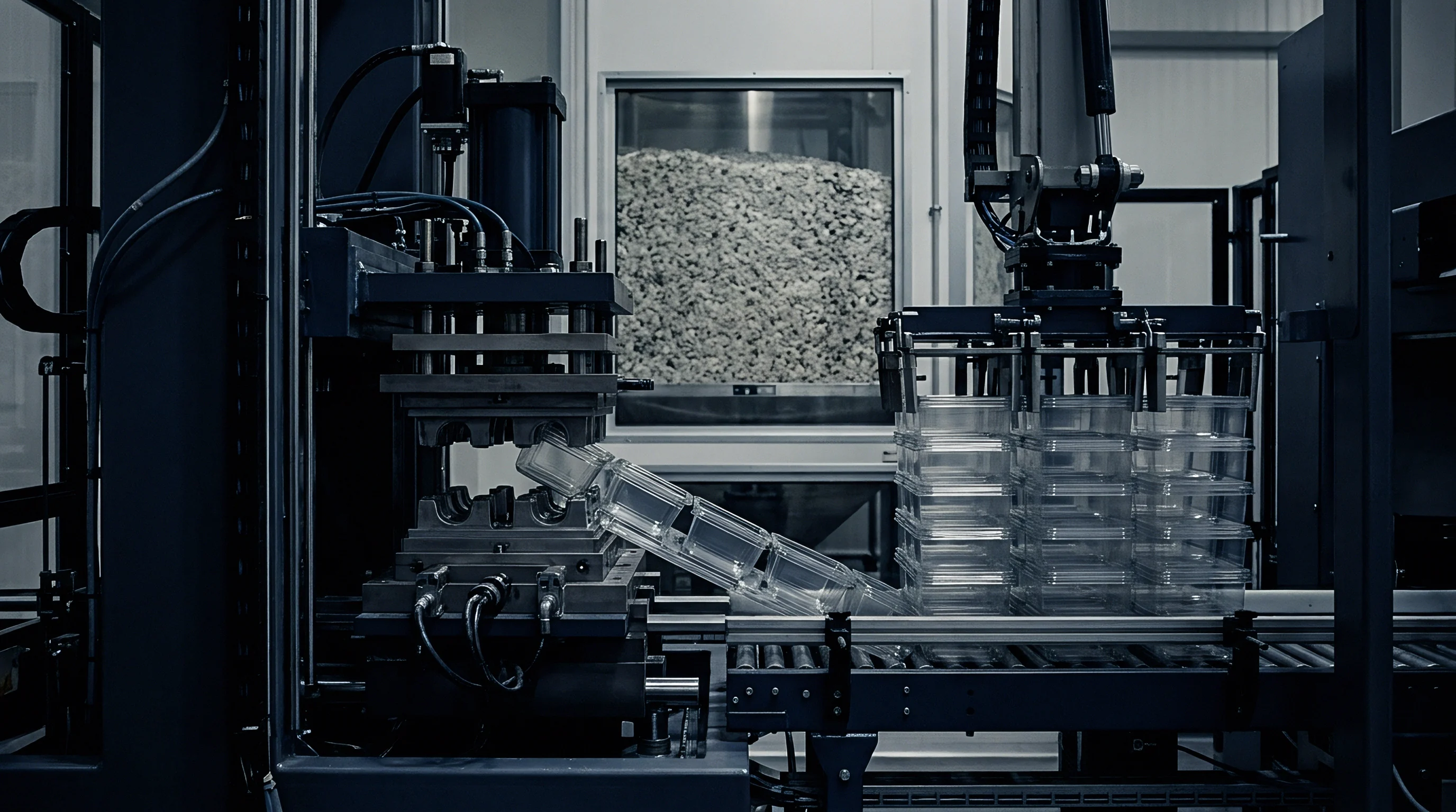
Settlement
Procurement agreements for high-cavitation micro-injection tooling must bridge physical metal expansion limits and commercial risk frameworks. Toolmakers routinely promise sub-micron tooling tolerances backed by room-temperature coordinate measuring machine data, but a tool measured at twenty degrees Celsius shifts baseline dimensions as soon as it reaches its one hundred forty degree Celsius operating temperature.

Commercial Allocation of Thermal Drift Risks
Amortizing ultra-precision mold costs over high-volume production relies on maintaining tight process capability indices. When dynamic steel expansion introduces a 0.5-micrometer variance into a feature with a 2.0-micrometer total tolerance band, capability indices drop below 1.33, pushing up scrap rates and eroding piece-part margins.
Tooling steel expands predictably under heat, but dynamic clamping deflection shifts cavity geometry irreversibly during production.
| Cavitation Level | Target Feature Tolerance (µm) | Dynamic Expansion Variance (µm) | Expected CPK Value | Financial Scrap Exposure (%) |
|---|---|---|---|---|
| 16 Cavities | ± 1.5 | 0.25 | 1.67 | 0.02 |
| 32 Cavities | ± 1.0 | 0.35 | 1.33 | 1.15 |
| 64 Cavities | ± 0.8 | 0.48 | 0.98 | 8.40 |
| 128 Cavities | ± 0.5 | 0.62 | 0.54 | 24.50 |

Final Acceptance Verification Documentation Criteria
Signing off on tool delivery requires documented proof of dimensional stability under operating heat, backed by calibrated sensor logs that verify cavity positioning during production.
- Hot Alignment Sign-off details physical core alignment measurements captured at maximum operating mold face temperatures.
- In-Process Pressure Calibration records dynamic transducer responses under full injection speed dry and wet runs.
- Thermal Mapping Dossier documents infrared surface temperature profiles across all cavity positions during continuous operations.
- Clamping Deflection Analysis quantifies plate distortion under full hydraulic tonnage using calibrated displacement sensors.
Precision tooling buyers sign off on cavity dimensions only after the mold reaches thermal equilibrium at full production speed.