Thermal Expansion and Mold Frame Deflection Adjustments for Angled Hydraulic Shutoffs
Angled hydraulic shutoffs demand deliberate cold clearances and mechanical preloads to balance thermal expansion against frame deflection and prevent flash.


Deflection
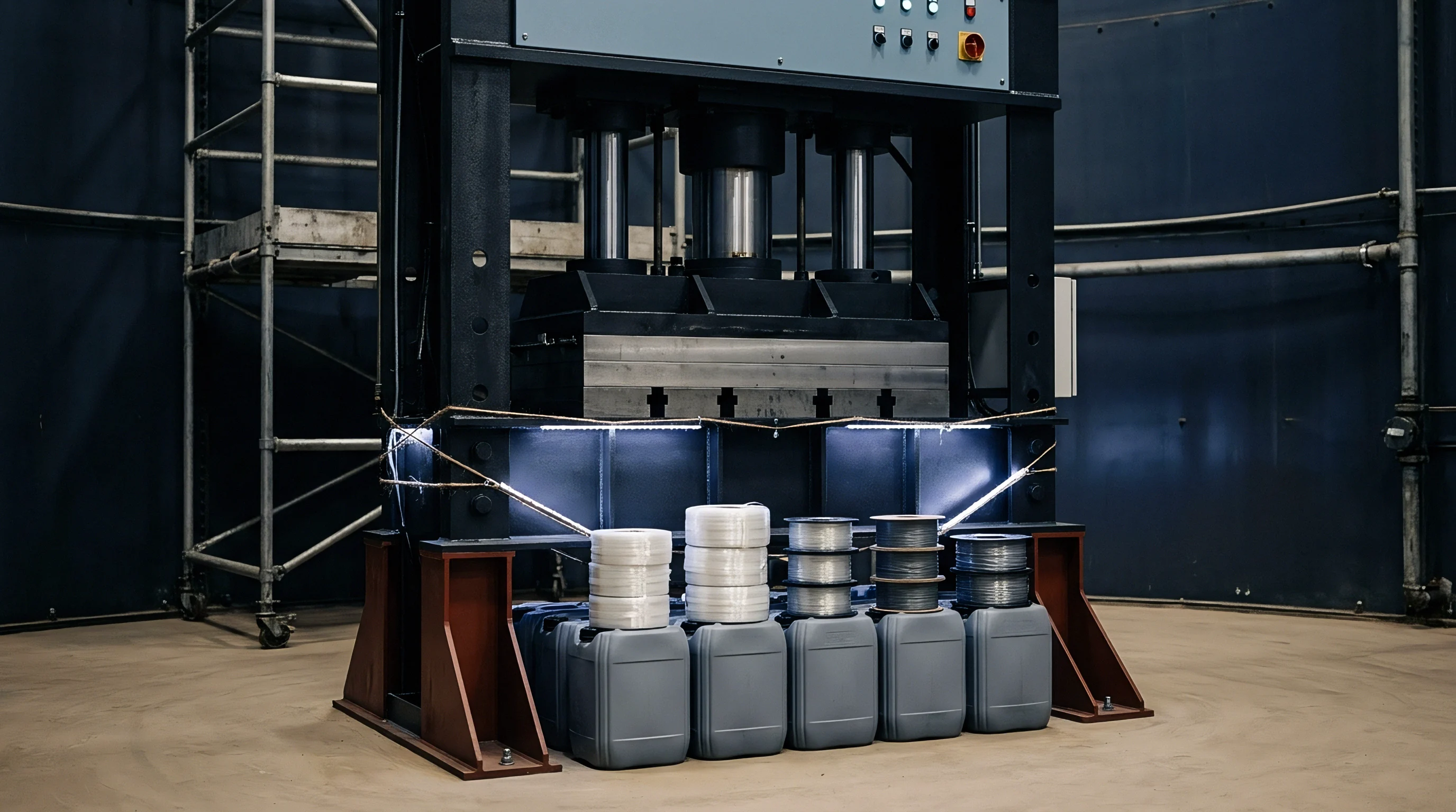
Separation Forces along the Vector
Placing an angled hydraulic core pull against incoming melt creates an immediate mechanical liability at the shutoff face. The melt pressure inside an injection mould commonly reaches 80 to 140 MPa during the pack phase. This fluid pressure acts across the projected area of the angled shutoff face, resolving into normal and shear components against the slide tip.
When a slide face sits at forty-five degrees to the press platen draw line, every hundred kilonewtons of axial melt force translates into seventy-point-seven kilonewtons of transverse side load pushing the core horn away from its seat. Standard hydraulic cylinders maintain static holding pressure via pilot-operated check valves, yet the fluid column inside the cylinder barrel remains compressible. Mineral-oil hydraulic fluid exhibits an effective bulk modulus between 1.4 and 1.8 GPa depending on aeration and operating temperature.
Under rapid cavity pressurization, this fluid column compresses, allowing the entire shutoff block to retreat axially by tenths of a millimetre before the mechanical locks fully bottom out.
Mechanical heel blocks absorb the primary lateral vectors once the mould reaches final clamping position. A heel block resting behind the angled slide wedge provides the ultimate physical barrier against deflection. Deflection still occurs across the entire stack: the slide body undergoes compressive strain, the heel block deflects as a cantilevered beam anchored to the mould base, and the ejector half backing plate bends under platen reaction loads.
Finite element analysis of standard medium-sized mould bases reveals that center-cavity deflection of backing plates under two thousand kilonewtons of clamp force routinely reaches 0.05 to 0.12 mm. This displacement alters the programmed shutoff clearance. The shutoff steel does not remain stationary during injection.
The interface shifts continuously through the filling, packing, and cooling phases.
A hydraulic cylinder holding a seventy-millimetre bore over a three-hundred-millimetre stroke permits 0.14 mm of axial retreat under eighty megapascals of cavity pressure strictly through fluid compressibility.
Uncontrolled core movement during the pack phase produces immediate parting-line flash. Flash forms when the opening gap exceeds the critical flash tolerance of the specific polymer grade. For low-viscosity polyamides, flash propagates into gaps as narrow as 0.010 mm.
For higher-viscosity polycarbonate or ABS, flash occurs when clearances breach 0.035 to 0.050 mm. A tool designer calculating shutoff preloads accounts for platen bending, heel block compliance, and cylinder retreat as a unified structural spring network. Tool builders frequently compensate by applying an aggressive mechanical interference fit to the shutoff face.
Excessive interference destroys the shutoff through galling during cycling. The mechanical solution balances preload against structural yield points.

Preload Calculations for Core Horns
Determining the mechanical interference between the angled core shutoff and the mating cavity insert demands rigorous summation of system deflections. The static deflection of the core slide assembly under peak pack pressure governs the minimum preload required to maintain seal integrity. Calculate the total linear deflection using the structural compliance of the slide steel combined with the bending of the supporting mould plate:
Deflection equals the applied normal force multiplied by the unsupported length, divided by the product of the cross-sectional area and the elastic modulus of the steel (delta = F L / (A E)). For an angled shutoff, the normal force F_n derived from peak cavity pressure P_cav acting on shutoff area A_shutoff at angle theta is expressed as F_n = P_cav A_shutoff sin(theta). In an H13 tool steel slide body with an elastic modulus of 210 GPa, a cross-sectional area of 4,000 square millimetres, and an effective length of 150 mm subjected to a 120 kN normal vector, the compressive deformation of the slide body alone accounts for 0.021 mm of displacement.
Backing plate deflection adds directly to this kinematic loss. A mould plate supported by rails deflects under clamping force following standard beam deflection models. The toolmaker compensates for this combined displacement by grinding the shutoff face proud relative to the nominal parting plane.
This proud condition represents the mechanical preload. If the calculated deflection totals 0.045 mm under peak cavity pressure, the cold preload must equal or slightly exceed this value to prevent flash. The preload cannot exceed the compressive yield strength of the steel at operating temperature, nor can it exceed the stroke force capacity of the hydraulic positioning system during mould closure.
Excess preload causes the angled surfaces to scrape aggressively, stripping surface coatings and inducing micro-welding at the shutoff perimeter.
The consequence of calculating this compliance incorrectly is rapid galling of the sliding faces followed by severe parting-line flash that halts production.


Thermal

Differential Expansion across Tool Plates
Temperature differences across injection moulds create dimensional changes that easily exceed typical part tolerances. Angled hydraulic shutoffs traverse multiple structural plates within the mould base. The slide body frequently mounts in an ambient-temperature or warm cavity plate, while the angled shutoff face mates with a core insert operating at an elevated temperature to promote resin flow or manage crystalline morphology.
Tool steels expand linearly according to their specific coefficient of thermal expansion. For conventional AISI P20 (1.2311) and premium H13 (1.2344), the coefficient of thermal expansion sits between 11.5 10^-6 / K and 12.8 10^-6 / K across the range from 20 to 200 degrees Celsius.
Consider a slide core measuring 250 mm from its rear mounting heel to the angled shutoff face. Running the core insert at 90 degrees Celsius for an engineering thermoplastic while the external mould frame and hydraulic cylinder mounting bracket sit at 30 degrees Celsius creates a 60-degree temperature gradient. The resulting linear thermal expansion along the slide axis equals 250 mm (12.2 10^-6 / K) 60 K, yielding 0.183 mm of growth.
Because the shutoff face sits at an angle, this axial expansion translates into both lateral interference and normal compressive stress against the mating steel.
Thermal expansion across a sixty-degree gradient generates over 0.18 mm of axial growth, turning nominal clearance into catastrophic interference.
Mould cooling channel placement governs local thermal equilibrium. Core slides frequently lack internal conformal cooling due to space limitations imposed by internal ejector pins, slide guide rails, and hydraulic rod attachments. Consequently, slide tips run hotter than the actively cooled cavity blocks they enter.
The slide expands continuously during the first two hours of continuous production, causing the initial cold-setup clearances to decay until the steel locks up entirely. Precise thermal channel placement within the slide body minimizes this thermal gradient. Beryllium-copper or high-conductivity copper-nickel-silicon alloys inserted into the core tip pull heat away from the sliding shutoff, stabilizing its geometry against the cooler cavity steel.
| Tool Material | Thermal Expansion (10^-6 / K) | Thermal Conductivity (W/m K) | Elastic Modulus (GPa) | Hardness Range (HRC) |
|---|---|---|---|---|
| AISI P20 (1.2311) | 12.8 | 29.0 | 205 | 28 to 32 |
| AISI H13 (1.2344) | 12.2 | 26.5 | 210 | 48 to 52 |
| AISI 420 (1.2083) | 10.8 | 24.0 | 215 | 50 to 54 |
| CuCr1Zr Alloy | 17.0 | 320.0 | 130 | 75 to 85 HRB |
| Ampcoloy 940 | 16.2 | 208.0 | 135 | 28 to 32 HRC |

Vector Decomposition on Inclined Parting Planes
Thermal growth in an angled shutoff resolves into vector components that dictate clearances along the mating surfaces. A shutoff plane oriented at an angle theta to the main draw direction experiences thermal growth along both the longitudinal tool axis (Z) and the transverse slide stroke axis (X). If the slide body expands by delta_L along its length, the normal displacement delta_N directed perpendicular to the angled shutoff face is expressed through trigonometric resolution: delta_N = delta_L sin(theta).
Simultaneously, the tangential sliding displacement along the shutoff face equals delta_T = delta_L cos(theta).
At shallow shutoff angles such as ten to fifteen degrees, axial thermal growth predominantly drives tangential sliding across the shutoff face. Tangential displacement causes sliding friction, demanding robust surface coatings and adequate lubricity. At steep shutoff angles between forty-five and seventy degrees, axial thermal growth directly increases normal contact pressure.
A steep shutoff angle transforms minute thermal expansions into massive compressive loads against the mating cavity steel. If the toolroom fits the shutoff to zero clearance at 20 degrees Celsius, heating the tool to operating temperature forces the steel beyond its yield limit. The slide horn indents the cavity block, creating a permanent pocket that flashes continuously once the tool cools.
Calculating the resultant vectors requires evaluating the thermal profile of both the male slide and the female receiving pocket. If both components reach identical operating temperatures and share identical steel alloys, uniform expansion preserves spatial clearances in open air. Within a restrained mould base constrained by external tie bars and clamp plates, boundary conditions alter this relationship.
The cavity pocket is restrained externally by the mould base, expanding inward toward the tool center. The core slide expands outward toward the pocket wall. The net effect is an amplification of contact interference rather than a cancellation.
Toolmakers reduce the slide tip length by an exact offset derived from the thermal delta before cutting final shutoff geometries.
Thermal equilibrium takes dozens of shots to stabilize completely. Tool setters often encounter a tool that operates smoothly for ten dry cycles during setup but galls violently thirty minutes into automated cycling. The differential expansion between the water-chilled mould plates and the uncooled hydraulic slide core steadily consumes the running clearance.
Compensating for this thermal gradient requires calculating the steady-state thermal field via thermal imaging or thermocouple data, followed by wire-EDM adjustments that leave clearance at room temperature to achieve a precise line-to-line contact at production temperature.
Failure to provide this thermal gap causes the slide to lock in forward position, triggering an emergency press stop when the main clamp attempts to close over an unseated slide.


Clearance

Wear Plate Offsets and Running Clearances
Running clearances for hydraulic slides operating angled shutoffs depend heavily on the guidance system controlling the slide stroke. Unlike standard cam-driven slides where angle pins separate from the slide block during the initial millimetres of mould opening, hydraulic slides remain under positive actuator control throughout the cycle. This continuous engagement requires precise running clearances along the guide gibs and wear plates.
Slide guidance systems require aluminum bronze wear plates with embedded graphite plugs or hardened tool steel plates (such as O1 or D2 at 58 to 62 HRC) running against lubricated H13 slide carriers. The baseline running clearance between the slide carrier and its guiding gibs sits between 0.015 and 0.025 mm at steady-state operating temperature.
Wear plate design incorporates shims beneath hardened ground plates to permit manual adjustment during commissioning. When machining the slide pocket, toolmakers leave a nominal 0.50 mm grind stock allowance on hardened sub-plates. As the mould wears or as thermal expansion changes alignment during initial trials, the toolroom grinds these shims to shift the slide trajectory.
A slide that runs with excessive lateral clearance tilts inside its guides under the offset force of the hydraulic cylinder rod. Angular cocking as small as 0.08 degrees causes the leading edge of an angled shutoff to strike the cavity pocket prematurely, shearing steel from the corner of the shutoff land.
| Resin Family | Tool Temp Range (Celsius) | Shutoff Angle (Degrees) | Cold Land Clearance (mm) | Operating Target Clearance (mm) |
|---|---|---|---|---|
| PA66 (Unfilled) | 80 to 110 | 10 to 20 | +0.012 to +0.018 | 0.000 to +0.005 |
| PA66 (30% Glass) | 80 to 110 | 10 to 20 | +0.020 to +0.025 | +0.005 to +0.010 |
| Polycarbonate | 85 to 125 | 15 to 30 | +0.025 to +0.035 | +0.005 to +0.012 |
| Polypropylene | 20 to 50 | 10 to 30 | +0.010 to +0.015 | 0.000 to +0.005 |
| PBT (15% Glass) | 60 to 90 | 15 to 45 | +0.018 to +0.025 | +0.003 to +0.008 |
| PEEK (Unfilled) | 160 to 200 | 20 to 45 | +0.045 to +0.060 | +0.005 to +0.012 |

Surface Treatments and Galling Prevention
Angled shutoffs experience combined sliding friction and high compressive contact stress, creating prime conditions for adhesive wear and galling. When two polished steel surfaces slide against each other under loads exceeding 20 MPa without lubrication, asperities on the metal surfaces cold-weld and shear off, destroying the precision shutoff edge. Galling completely ruins parting-line seal integrity, demanding extensive laser welding and bench re-fitting.
Selecting distinct, compatible materials for sliding pairs mitigates this mechanism entirely. The moving slide face and the stationary cavity seat must never share identical hardness and alloy composition unless a specialized surface diffusion layer or physical vapor deposition (PVD) coating intervenes.
Applying surface coatings increases surface hardness and lowers the coefficient of friction across the shutoff interface:
- Titanium carbo-nitride coatings provide a surface hardness exceeding 3,000 Vickers with a friction coefficient below 0.20 against polished steel, preventing micro-welding at elevated operating temperatures.
- Diamond-like carbon films deposit an amorphous carbon matrix that runs completely dry without liquid lubrication, preventing resin contamination on medical or optical moulding surfaces.
- Plasma nitriding treatments diffuse nitrogen directly into the tool steel matrix to achieve a case depth between 0.10 and 0.25 mm at 65 to 68 HRC, ensuring the core retains compressive core strength without the flaking risks associated with thick galvanic platings.
- High-phosphorus electroless nickel deposits an amorphous alloy layer containing ten to twelve percent phosphorus that yields exceptional corrosion resistance against outgassing fluoropolymers while delivering lubricious sliding contact.
Lubrication inside cleanroom moulding environments faces tight regulatory limits. Food-contact and medical packaging prohibit standard grease lubricants along moving slides near the cavity parting line. In these tools, designers rely exclusively on self-lubricating graphite-impregnated sintered bronze wear plates paired with coated tool steel slide bodies.
The shutoff land itself remains completely free of lubricant. Any grease placed on the shutoff face migrates directly into the cavity, generating cosmetic blemishes and compromising structural weld lines in the moulded component.
Tool builders often complain that modern anti-wear coatings add unnecessary expense to a tooling quote, yet repairing a single galled shutoff pocket in production costs ten times the initial coating application.

Hydraulics

Cylinder Sizing under Injection Pressure
Sizing the hydraulic cylinder for an angled shutoff requires balancing two opposing force conditions: pulling force to break vacuum and overcome slide friction during tool opening, and holding force to resist melt pushback during injection. Molders frequently rely solely on the mechanical wedge lock to resist injection pressure, using the hydraulic cylinder merely to position the slide. In complex tools featuring angled shutoffs, the core often pulls prior to main parting line separation, or the slide angle prevents the mechanical heel from engaging until the final millimetres of mould stroke.
When the cylinder directly resists cavity pressure without a secondary heel lock, sizing errors cause immediate tool separation.
The holding force F_hold exerted by a hydraulic cylinder equals the effective piston area A_piston multiplied by the system hydraulic pressure P_hyd (F_hold = A_piston P_hyd). The opposing force generated by injection melt equals the projected area of the core tip along the cylinder stroke axis multiplied by peak cavity pressure. For a shutoff surface projecting 1,500 square millimetres along the stroke axis exposed to an 85 MPa pack pressure, the resulting pushback force equals 127.5 kN.
To resist this force using a standard plant hydraulic system running at 14 MPa (140 bar), the cylinder piston area must exceed 9,107 square millimetres. This demands a minimum cylinder bore diameter of 108 mm. Installing a compact 63 mm bore cylinder under these conditions guarantees that the core blows back during the pack stage, flashing the mould and creating scrap.
Relying on a hydraulic cylinder without an integrated mechanical wedge lock demands enormous piston areas to counter standard eighty-megapascal pack vectors.
Hydraulic system pressure is not completely stable across an entire plant. In facilities running central hydraulic loops or older presses with proportional valve droop, line pressure fluctuates by twenty percent depending on adjacent machine cycles. Sizing calculations must incorporate a safety factor of at least 1.5 against the press circuit minimum operating pressure, rather than the nominal pump output pressure.
If the hydraulic circuit pressure drops to 11 MPa during an unexpected accumulator recharge, a marginal cylinder yields immediately to cavity pressure.

Manifold Valving and Intensification Risks
The structural geometry of hydraulic cylinders introduces fluid intensification risks during mould operation. Injection moulding tools utilize double-acting hydraulic cylinders with differential areas between the bore side and the rod side. When cavity melt pressure pushes against the slide tip, it forces the cylinder piston backward against trapped fluid in the cylinder barrel.
If the hydraulic control circuit incorporates a pilot-operated check valve on the cap end of the cylinder, this trapped oil cannot escape. The external pushback force intensifies the fluid pressure inside the cylinder cap end according to the ratio of the core area to the piston area.
Intensified pressures can rapidly exceed the burst rating of the cylinder barrel, manifold blocks, and hydraulic hose fittings. Standard industrial cylinders carry working pressure ratings of 16 to 21 MPa, with burst limits near 40 to 50 MPa. If peak injection forces push the effective cap-end pressure up to 60 MPa, the cylinder seals deform, blow out, or fracture the cylinder mounting tie rods.
Preventing intensification failure requires engineered pressure relief valves mounted directly to the slide manifold block, or the inclusion of positive mechanical wedge locks that eliminate fluid load during injection entirely.
Cylinder sequencing must sync flawlessly with machine clamp kinematic cycles. Angled slides travel across the path of the main ejector pins or opposing cavity inserts. If the hydraulic cylinder stroke drifts or lags due to cold oil viscosity during a morning startup, the main clamp closing stroke crushes the misaligned slide tip.
Modern tool standards dictate inductive proximity sensors or linear transducers embedded directly into the cylinder body to verify full stroke extension and retraction. Standard external mechanical microswitches fail frequently under vibration and oil contamination, giving false slide-ready signals that lead directly to tool crashes.
The supplier provides warranty replacements for deformed cylinder rods, but refuses compensation for the wrecked cavity inserts crushed by the mechanical failure.
Qualification

Inspection Protocols for Angled Interfaces
Validating the shutoff geometry requires dedicated metrology procedures before the tool leaves the toolroom. Blueing trials represent the traditional baseline method for evaluating shutoff contact patterns. Toolmakers apply high-spotting Prussian blue paste to the angled shutoff face of the slide core and slowly close the slide into its cavity pocket using hand pressure or low-pressure hydraulic jogs.
When retracted, the mating faces must reveal a uniform transfer pattern across the designated seal land. A reliable shutoff seal demands an unbroken contact band measuring at least five to eight millimetres wide along the entire cavity perimeter, demonstrating at least eighty-five percent contact area density.
Blueing trials performed at room temperature fail to predict thermal equilibrium behavior. The tool qualification protocol mandates a heated dry-cycle verification on the bench. Technicians connect hot-oil or pressurized-water temperature control units to the slide and cavity circuits, bringing all tool components to their specified operating temperatures (such as 80 degrees Celsius core, 60 degrees Celsius cavity).
Technicians then repeat the contact check using temperature-resistant marking compounds or micron-thickness lead foil shims. Gauging the deformation of lead foil strips placed along the shutoff face reveals whether thermal expansion has introduced severe pinch points or opened up flash clearances under operational conditions.
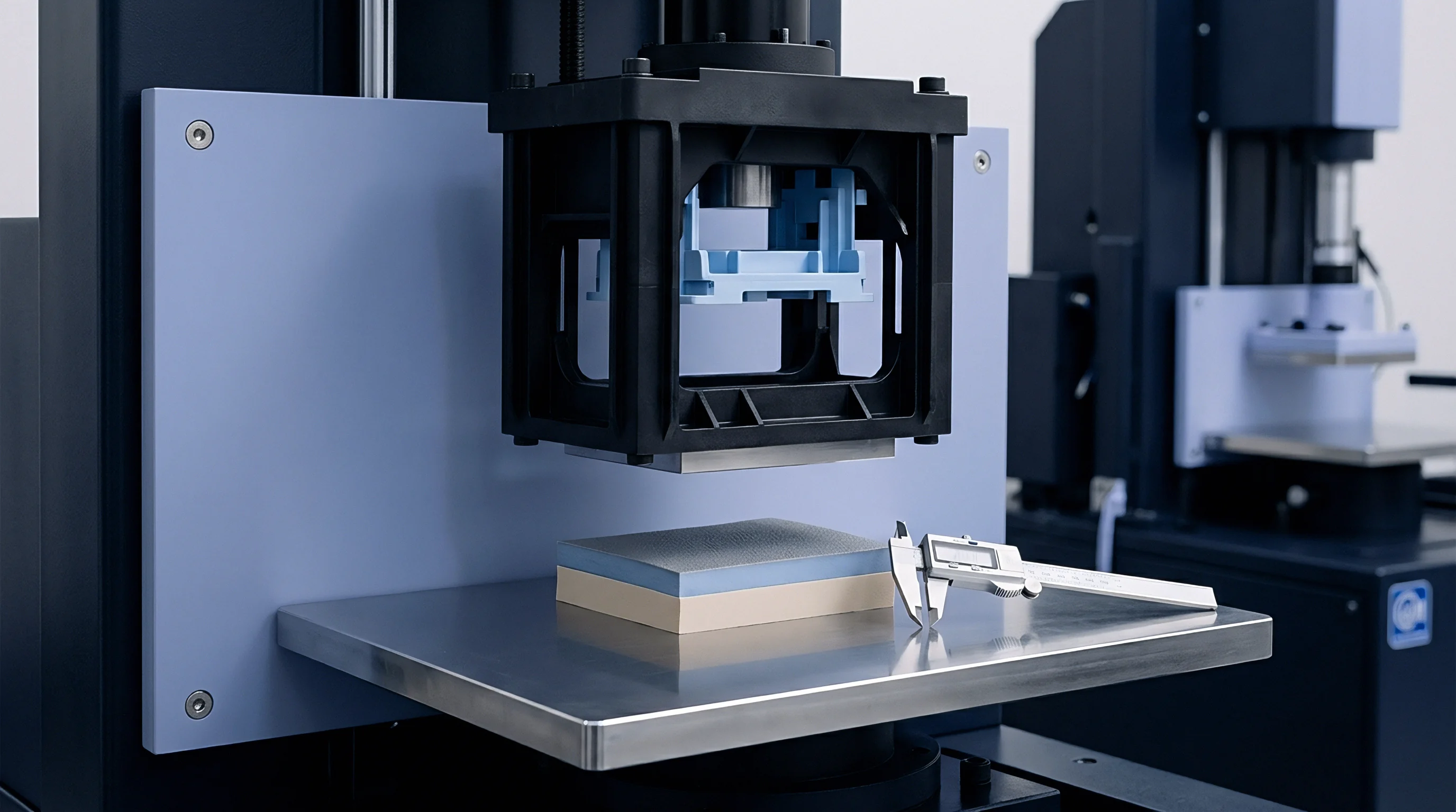
Co-ordinate measuring machines (CMM) verify the free-state geometry of the slide and cavity pocket relative to master tooling datums. Modern multi-axis optical scanners generate dense point clouds of the complex angled shutoffs, comparing the machined surfaces against native 3D CAD models. This inspection verifies:
- The true vector angle of the shutoff face matches engineering models within plus or minus six arcminutes.
- Profile tolerance across the shutoff land remains inside 0.005 mm total indicator reading relative to primary guide rails.
- Perpendicularity of the slide carrier body to its base seat conforms to a 0.008 mm tolerance band.
- True position of the hydraulic cylinder mounting centerline falls within 0.05 mm of the slide stroke axis to prevent side loading on the cylinder gland seals.
Should Moulders Adjust Shutoffs through Process Shimming?
When parting-line flash appears on an angled core during tool trials, process technicians face a choice: adjust the steel permanently or install shims behind the wear plates. Shimming a tool on the press platen provides immediate gratification by shifting the slide closer to its seat, suppressing flash within minutes. This practice introduces significant mechanical risk.
Shimming alters the kinematic relationship between the slide, the guiding gibs, and the mechanical heel block. Moving the slide forward via shims without adjusting the heel block causes the entire injection pack load to transfer directly onto the slide guidance rails and hydraulic cylinder rod, bypassing the primary load-bearing heel structure.
Field data confirms that tools adjusted via unauthorized press-side shims suffer catastrophic guide rail failure or heel block cracking within fifty thousand cycles. The proper procedure requires pulling the tool from the press, measuring the exact contact pattern on a coordinate measuring machine, and precision-grinding the hardened steel components in a controlled toolroom environment. Adjustments must maintain simultaneous, parallel contact across both the forward shutoff face and the rear mechanical heel block.
If the heel block fails to seat precisely as the shutoff lands touch, the slide flexes dynamically under every shot, accelerating steel fatigue and inducing parting-line degradation.
DIN 16742 outlines achievable tolerance classes for plastic mouldings, establishing how steel variation directly correlates to finished part dimensions. Holding tight tolerance classes (such as DIN 16742 TG4 for engineering components) demands that tooling shutoffs maintain repeatable positional accuracy inside 0.010 mm across months of continuous production. Moulders attempting to control flash through dynamic process adjustments, such as dropping pack pressure or speeding up injection velocity, narrow their stable processing window.
Once process parameters are restricted purely to compensate for bad steel clearances, slight raw material viscosity variations push parts into either flash or non-fill defects.
The standard tooling supply agreement explicitly voids the warranty if press setters alter slide mechanics or insert hand-cut shims behind wear surfaces without engineering sign-off.


Amortisation

Tool Life and Preventative Maintenance Costs
Angled hydraulic shutoffs represent a high maintenance liability over the life of an injection moulding tool. The combination of thermal cycling, mechanical impact, and sliding friction degrades alignment faster than standard stationary parting lines. Budgeting for tool amortisation requires factoring in scheduled refurbishments for sliding shutoff components.
In high-volume production running abrasive glass-filled resins (such as thirty percent glass-reinforced PA66 or PBT), sliding shutoff lands experience severe erosive and adhesive wear, requiring planned maintenance every one hundred thousand to one hundred fifty thousand cycles.
Preventative maintenance protocols for angled shutoffs include replacing bronze wear strips, inspecting guide gib clearances, non-destructive crack testing of core horns, and replacing cylinder rod seals. A typical mid-life tooling refurbishment for a four-cavity tool with multiple angled hydraulic cores costs between eight thousand and fourteen thousand dollars, requiring three to five days of press downtime. Failing to budget for these scheduled refurbishments leads to unexpected tool pulls when the shutoffs gall in the middle of a production run, escalating scrap costs and threatening delivery commitments.
| Tooling Asset Stage | Initial Capital Cost (USD) | Refurbishment Cycle (Shots) | Cost Per Refurbishment (USD) | Total Lifecycle Cost (USD) | Amortised Cost Per Shot (USD) |
|---|---|---|---|---|---|
| Standard Mechanical Cam Slide | 32,000 | 250,000 | 3,500 | 42,500 | 0.0425 |
| Angled Hydraulic Slide (Uncoated H13) | 44,000 | 125,000 | 7,200 | 94,400 | 0.0944 |
| Angled Hydraulic Slide (PVD Coated + Sensors) | 52,000 | 200,000 | 5,500 | 74,000 | 0.0740 |
| Hydraulic Core with Conformal Cooling | 68,000 | 175,000 | 6,800 | 102,000 | 0.1020 |
Financial Exposure in Tool Transfer Contracts
Transferring an existing tool with angled hydraulic shutoffs between moulding facilities introduces substantial financial and operational risk. Tool ownership disputes frequently arise when an incoming moulder attempts to run a transferred tool and experiences immediate slide lockup or severe flashing. The root cause usually traces back to subtle differences in the operating environments of the two facilities.
Facility A may have operated the tool on an electric press with rigid platens and a tightly controlled central water system providing 12-degree chill water. Facility B mounts the tool in an older hydraulic press with significant platen deflection and a cooling tower delivering 25-degree water.
This environmental shift alters the steady-state thermal gradients and mechanical deflections across the angled shutoffs. The incoming moulder finds that the slides gall within two hours of bring-up. If the tool transfer agreement lacks explicit language defining thermal validation, machine platen stiffness minimums, and pre-transfer sign-off parts, the buyer faces massive unbudgeted expenses.
The original moulder claims the tool was fully operational upon departure, while the receiving moulder asserts the tool was transferred in a defective, worn-out state.
Robust sourcing agreements protect the buyer by incorporating rigorous tooling dossiers that specify exact machine-side operating parameters. The contract must mandate that the tool runs a continuous four-hour capability run producing parts within defined Cpk limits immediately prior to crate packing. The dossier accompanying the tool must record hydraulic line pressures, cylinder timing sequences, coolant circuit flow rates and temperatures, and coordinate inspection reports of the shutoffs in both cold and hot states.
Clear contract language assigns financial responsibility for initial dry-run alignment verification to the receiving moulder prior to firing the first production shot.
A tooling contract missing these machine compatibility baselines leaves the buyer paying tooling modification invoices twice for a tool they thought they already owned.