Injection Mold Parting Line Wear Inspection Basics
Inspect parting line wear using optical blueing and depth micrometer checks to catch shutoff hobbing before flash exceeds 0.03 mm.


Land
Sealing along the parting line relies on controlled elastic deformation between mating tool steel surfaces. When an injection mold closes under hydraulic or mechanical clamp force, the primary shutoff area takes the initial contact load. Usually designed with a relief back-off behind a narrow 1.5 mm to 3.0 mm sealing land, this area undergoes compressive stress that often exceeds the yield point of softer steel alloys.
Tool designers balance contact area against press tonnage so the mold seals cleanly without micro-deforming the steel. Too little shutoff area crushes the metal locally; too much land area spreads the clamping force thin, allowing internal cavity pressure to force the parting interface open.
Steel selection determines how well a tool holds up against parting line wear. Hardened alloys like H13, S7, and Stavax ESR undergo micro-structural shifts after thousands of thermal and mechanical cycles. For high-cavitation production molds, mating faces are specified with differential hardness values ~ usually a 2 to 4 HRC difference between core and cavity shutoffs ~ to prevent adhesive galling during rapid closure.
Even with proper steel selection, high injection pressures driving glass-reinforced resins across the parting line produce combined wear mechanisms that steadily degrade the fit of the shutoff surfaces.

Shutoff Geometry and Primary Contact Forces
Flat shutoffs perpendicular to press travel take direct compressive loads. Angle shutoffs ~ used around side-action sliders and deep core penetrations ~ face both compression and sliding friction. Standard draft angles on shutoff faces run between 3 degrees and 7 degrees, though tight-tolerance electronic connector molds often tighten this to 1.5 degrees.
Shallower angles raise the risk of surface scuffing as the mold closes, especially if guide pins and bushings suffer from mechanical wear or unequal thermal expansion.
Calculating compressive stress along the parting line requires comparing total contact area against clamping tonnage. A mold with 4,500 square millimeters of total shutoff area under a 2,000 kN clamp force operates at a nominal contact stress of 444 MPa. But if steel debris, resin flakes, or flash get trapped between the halves, the actual contact area shrinks fast.
Localized stresses can easily exceed the 1,200 MPa yield limit of heat-treated H13 steel at 50 HRC, permanently hobbing the shutoff face.
Parting line shutoff surfaces ground to 1.2343 tool steel at 52 HRC maintain integrity for 250,000 cycles under 150 kN clamp force before micro-hobbing exceeds 8 µm.

Mechanical Wear Modes on Mating Tool Steels
Abrasive wear takes over when molding polymers loaded with glass fibers or mineral fillers. Fiber ends sticking out from the melt stream scour ground steel lands during final packing. Over hundreds of thousands of cycles, this friction rounds off the sharp shutoff corners, opening up the tight radial clearance needed to hold back molten resin.
Hobbing represents a different failure mode: high contact forces at localized spots sink sections of the shutoff land directly into the opposing steel face. It usually stems from uneven thermal expansion when a hotter core expands more than the water-cooled cavity plate, concentrating clamp pressure on the outer peripheral lands. Micro-fretting happens concurrently, as tiny lateral movements during peak injection pressure produce microscopic pits and oxide debris along the shutoff boundary.
| Steel Grade | Hardness Range (HRC) | Yield Strength (MPa) | Compressive Fatigue Limit | Primary Wear Mechanism |
|---|---|---|---|---|
| AISI P20 (1.2311) | 28 – 32 | 850 | Low | Hobbing and Abrasive Scouring |
| AISI H13 (1.2344) | 48 – 52 | 1450 | Moderate | Micro-Fretting and Thermal Cracking |
| AISI S7 | 54 – 58 | 1750 | High | Edge Chipping under Impact |
| Stavax ESR (1.2083) | 50 – 54 | 1500 | Moderate-High | Corrosive Etching and Abrasion |
| CPM 1V / 9V | 58 – 62 | 2100 | Very High | Fine Micro-Abrasive Wear |
Thermal cycling accelerates mechanical wear. Because cavity surfaces cycle between hot melt and chilled steel during cooling, differential expansion causes minute sliding motions along the shutoff edge. Metal fatigue emerges as micro-cracking along these boundaries, eventually causing small flakes of steel to break off.
Running tools without proper pre-heating risks immediate damage, because cold shutoffs take uneven tonnage before the mold reaches thermal equilibrium.
Parting line flash is often attributed to platen flexure rather than steel compression on shutoff lands.

Flash
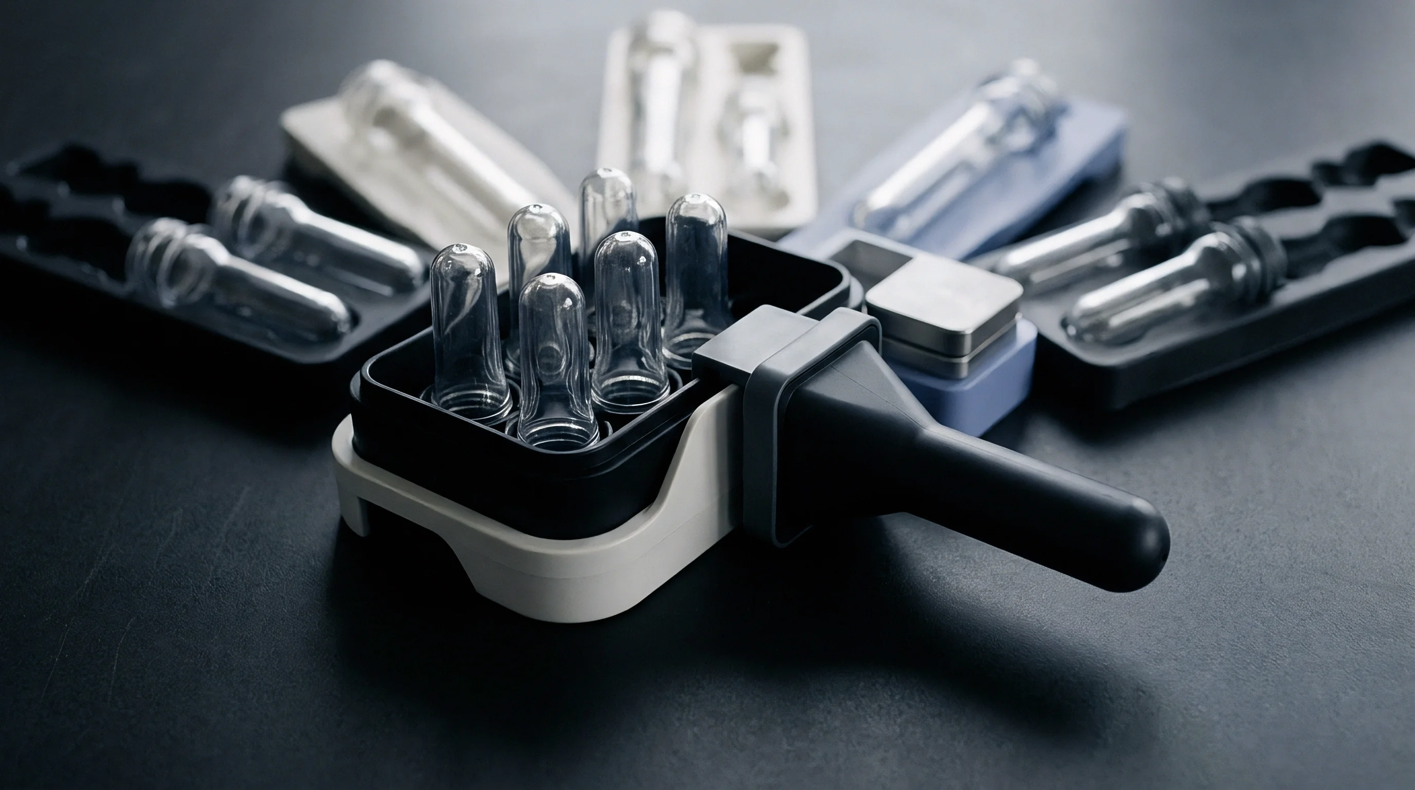
Polymer melt creeps into microscopic voids whenever parting line contact pressure drops below local cavity pressure. During injection, internal cavity pressures hit anywhere from 30 MPa to 180 MPa, depending on resin viscosity, wall thickness, and flow length. If wear drops localized contact stress below that fluid threshold, molten plastic forces the mold faces apart by a few microns.
That creates part flash ~ a thin web of plastic bleeding past the nominal part geometry along the parting line.
Fluid dynamics and shear rate dictate how easily flash forms. Viscous resins like unreinforced Polypropylene need wider gaps to flash than low-viscosity materials such as liquid crystal polymers or unfilled Nylon 66. Under high packing pressure, PA66 flashes through a gap as small as 0.01 mm, while ABS usually needs a gap over 0.03 mm before resin bleeds into the parting space.
Diagnosing shutoff wear means weighing flash thickness against the viscosity behavior of the resin being processed.

Viscosity Thresholds and Flash Penetration Gaps
Rheology under high shear rates determines how far melt creeps into a worn shutoff gap. Faster injection speeds cause shear thinning, lowering melt viscosity near the cavity walls. That thinner resin flows quickly into microscopic gaps left by hobbing or abrasive wear.
Increasing injection speed to resolve burn marks often causes heavy parting line flash instead, as the thinned polymer slips across worn shutoff lands.
Crystalline structure matters as well. Amorphous polymers stay more viscous near their glass transition temperature, providing a buffer against slight shutoff wear. Semi-crystalline polymers drop sharply in viscosity as they melt, seeping into tight gaps readily.
Fiber-reinforced resins present a dual problem: glass fibers raise bulk viscosity, but loose fiber ends act like tiny wedges at the shutoff edge, propping worn steel faces open while matrix resin streams past.
Evaluating parting line condition requires tracking the specific wear failure modes present across the mold faces:
- Hobbing Crushing happens when excessive clamp tonnage deforms local shutoff lands, leaving permanent depressions that let melt bleed through during peak packing.
- Micro-Fretting shows up as localized pitting from tiny movements between core and cavity plates during the pressure pulse of injection.
- Vent Erosion occurs where gas vents meet the parting land, where high-velocity gas and corrosive volatiles scour steel away over time.
- Parting Line Debris Bedding happens when crushed plastic flakes or shop dirt get stamped into softer steel lands, ruining flat shutoff contact.

Clamping Pressure Dynamics and Hydraulic Compression
Clamp force keeps mold halves closed against internal cavity pressure, but running excessive tonnage speeds up shutoff wear. Hydraulic and electric presses compress tool steel elastically during lockup. On narrow shutoff lands, high clamping tonnage generates severe local pressure that crushes the steel over time.
Once that stress exceeds the yield point, the lands plastically deform, leaving a permanent gap even under normal clamp settings.
Dynamic platen flex compounds this issue. Under full tonnage, press platens bow outward slightly at the center, causing the mold plates to follow suit. That reduces clamping pressure near the center while concentrating heavy tonnage along the outer edges of the parting line.
In multi-cavity molds, center cavities tend to show wear from flash erosion, whereas outer cavities show damage from crushed steel. Keeping strain balanced across the platen face is critical to avoid premature shutoff failure.
DIN 16742 Group 140 tolerance enforcement fails once parting line shutoff degradation creates flash exceeding 0.05 mm across secondary seals.

When Does Shutoff Wear Exceed Tooling Limits?
Wear hits a hard limit when flash exceeds the functional or visual tolerances on the part print. In precision electronic connectors, flash over 0.02 mm can stop components from seating or trip up automated surface-mount lines. On consumer housings, flash taller than 0.08 mm creates a sharp edge that fails touch checks, forcing manual deburring that destroys part margins.
Deciding whether to send a tool for repair or adjust the process comes down to measuring flash against wall thickness tolerances. If parting line wear hits 0.03 mm on a part with a 0.8 mm nominal wall, that wall grows by nearly four percent at the parting line. The extra material binds up auto-ejection, increases draft friction, and creates stress concentrations in the part.
Processing adjustments cannot restore missing steel ~ once shutoffs suffer permanent hobbing, physical tool repair is the only option.
Whether high-speed multi-cavity tools can maintain 0.01 mm shutoff precision past two million cycles without mid-life re-facing remains debated.

Imprint
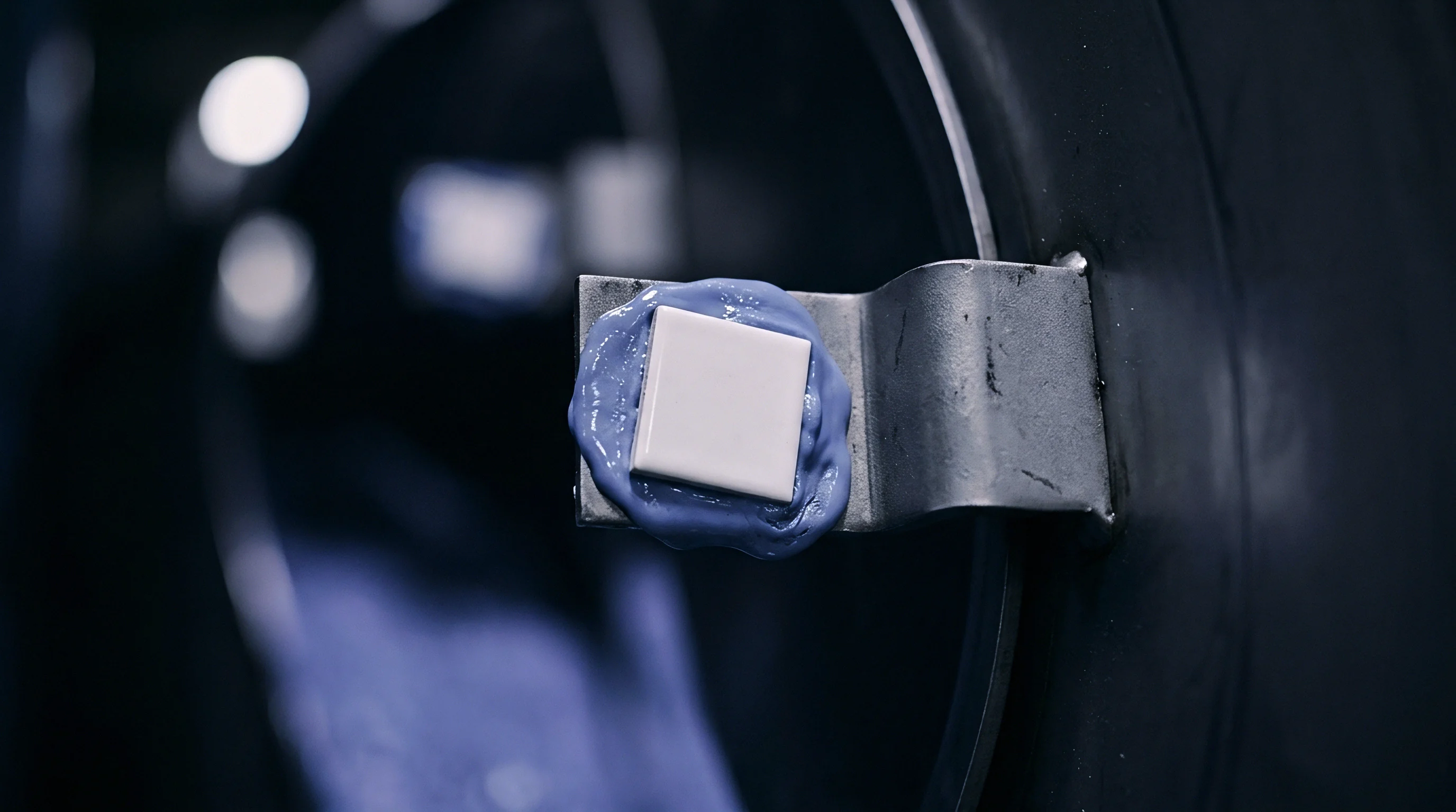
Bench checks verify mold face parallelism by reading dye transfer patterns under static clamp pressure. Toolmakers apply thin layers of Prussian blueing compound to evaluate shutoff contact before placing the mold in a press. It provides a quick visual map of high spots, low spots, and worn areas across both tool halves, showing whether lands seal evenly or localized hobbing has opened leak paths.
Dye testing shows where contact occurs, but it does not measure how deep wear goes or what the gap looks like under load. For quantitative data, tooling engineers rely on feeler gauges, lead wire compression tests, white-light optical profilometry, and portable depth micrometers. Exact steel loss numbers clarify whether a land needs a localized spot-grind or a complete laser-weld repair.

Prussian Blue Transfer and High Spot Identification
Applying Prussian blue requires careful technique to avoid false readings. The dye is wiped onto clean shutoff steel with a lint-free applicator to achieve an even film thickness between 0.002 mm and 0.005 mm. Heavy blueing hides micro-gaps, making damaged lands look fully sealed.
The toolmaker brings the mold halves together under light bench-press tonnage or clamp pressure, then separates them to check transfer between core and cavity.
Transfer patterns reflect the extent of steel deformation. Areas where dye squeezes out completely to the metal edge are high-pressure zones actively crushing steel. Uncompressed dye indicates low areas where wear has opened a gap.
A healthy mold shows even 80 percent to 90 percent transfer across all functional sealing lands, with sharp cutoffs at the relief steps.
- Clean both mold halves with solvent degreaser to remove resin residues, oils, and anti-rust coatings from shutoff surfaces.
- Apply a thin film of Prussian blueing compound to the primary sealing lands on the stationary cavity half with a high-density foam roller.
- Guide the moving core half into engagement using precision alignment pillars, bringing mold faces together under controlled bench-press tonnage.
- Separate the mold halves cleanly without twisting or lateral shift so the transfer pattern remains undisturbed.
- Document the transfer imprint with high-resolution photos, noting areas with incomplete dye transfer or heavy squeeze-out.
- Measure low spot depths across affected shutoff zones using a calibrated optical profilometer or digital contact probe.

Optical Profilometry and Direct Contact Gauging
Non-contact optical profilometry maps 3D surface topography without touching delicate mold lands. White-light interferometry and laser scanners record profile data at sub-micron vertical resolution, generating color height maps that pinpoint crater depths, scratch profiles, and edge rounding along worn parting lines. Measuring optically eliminates operator variation common with feeler gauges, providing repeatable data for tooling records.
Direct contact gauging remains necessary for press-side troubleshooting when optical tools are not practical on the floor. Lead wire testing involves placing soft lead or aluminum wire across shutoff lands, clamping the mold at full tonnage, and measuring the compressed wire with a micrometer. Comparing those compressed wire dimensions against tool drawings reveals local shutoff gaps accurate to 0.005 mm.
Higher injection pressure always forces plastic melt into smaller shutoff clearance gaps than static clamp tonnage alone can seal.
Scrapping thirty thousand dollars in automotive connector housings often traces back to relying on visual checks alone instead of depth micrometer verification across worn shutoff lands.


Strain
Dynamic forces during press lockup cause uneven movement across worn steel shutoffs. Machine platen stiffness, tie bar stretch, and hydraulic pressure determine the exact force striking the parting lands. When shutoffs wear unevenly, mold faces stop meeting parallel to the platen face.
That imbalance introduces bending moments into tie bars, wears down guide pins, and creates cyclic strain that degrades machine alignment over long runs.
Tracking dynamic mold movement during production catches real-time parting line separation that bench checks miss. Molten plastic entering the cavity under high pressure acts like a hydraulic jack pushing core and cavity plates apart. Mounting strain gauges, load cells, and linear displacement sensors on the tool or platens allows monitoring of micro-scale parting line breathing during filling and packing.

Dynamic Parting Line Separation Sensors
Inductive eddy-current sensors and linear variable differential transformers (LVDTs) mounted at the four corners of the mold base measure plate separation in real time. Streaming continuous displacement data to the press controller, they log a separation event whenever cavity pressure forces the parting line open past 0.015 mm during packing. Repeated flex at specific corners points directly to local shutoff wear or uneven clamp force distribution.
Piezoelectric strain sensors bolted to tie bars provide complementary data by tracking load distribution across the clamp assembly. Unequal strain across the bars indicates that worn shutoffs are tilting the mold during lockup. Correcting this requires shimming the mold base or re-machining worn shutoffs to re-balance tonnage across all four tie bars.
| Sensing Technology | Measurement Metric | Resolution | Sampling Rate | Primary Implementation Advantage |
|---|---|---|---|---|
| Eddy-Current Proximity Sensors | Plate-to-plate displacement | 0.5 µm | 10 kHz | Immune to oil and coolants in parting gap |
| High-Speed LVDTs | Absolute parting line gap width | 0.1 µm | 2 kHz | High absolute dimensional accuracy |
| Tie-Bar Strain Gauges | Asymmetrical clamp load flexure | 1.0 N/mm² | 1 kHz | Detects tool tilt induced by uneven wear |
| Piezoelectric Load Washers | Dynamic contact stress under clamp | 10 N | 20 kHz | Captures micro-second pressure spikes |

Tie Bar Tonnage Distribution and Deflection
Unequal clamp force accelerates shutoff failure. When one corner of a mold shutoff hobs or wears down, the machine transfers extra clamping load onto the unworn quadrants. That concentrated force can exceed the yield strength of the remaining steel, triggering progressive collapse across the entire parting face.
Monitoring tie bar strain outputs keeps tonnage variance across all four bars under five percent.
Platen deflection maps show why mold dimensions must fit the press platen properly. Running a small tool with high shutoff lands in a high-tonnage machine concentrates clamping load near the center, flexing the platen around the mold edges. This flex crushes inner shutoffs while letting outer vents flash.
Proper sizing or adding support pillars behind cavity inserts keeps platens from crushing the parting line.
Toolmakers identify local shutoff crushing long before flash appears on molded part edge profiles.
Excessive clamp tonnage fatigue-damages shutoff steel far faster than melt pressure ever wears it down.


Refit
Restoring worn shutoff lands requires depositing new material precisely without altering surrounding cavity details. Once shutoff hobbing or abrasive wear passes 0.02 mm, process adjustments no longer stop flash. Toolmakers must re-establish datum planes, build up damaged steel edges, and re-machine shutoff angles back to print specifications.
The choice of refurbishment method balances repair costs against remaining tool life.
Laser micro-welding is standard for parting line repair because it delivers tight heat input with minimal thermal distortion. Traditional Gas Tungsten Arc Welding (TIG) introduces excessive heat into the mold plate, causing heat-affected zone softening, internal stress, and warping in nearby cavity features. Laser welding deposits small micro-beads of matching steel wire on eroded edges, forming a metallurgical bond that requires minimal cleanup.

Laser Welding and Tool Steel Restoration
Micro-laser welding uses pulsed laser beams to fuse filler wire between 0.1 mm and 0.4 mm in diameter onto damaged shutoff edges. The heat-affected zone remains compact enough that parent metal hardness stays unchanged 0.5 mm from the weld bead. Wire chemistry must match the mold steel; welding an H13 insert with mild steel wire leaves soft spots that collapse after a few thousand cycles under normal tonnage.
Post-weld finishing relies on hand lapping, CNC spot-grinding, or sinker EDM to take the weld bead back down to the surrounding shutoff datum. Toolmakers stone and polish welds flush with fine abrasives and diamond paste, checking flatness under optical flats or shop microscopes. High spots left by poor grinding concentrate clamp tonnage, causing secondary hobbing on the opposing tool face.
- Verify Steel Metallurgy to match filler wire composition directly to base mold steel specs before starting laser deposition.
- Pre-Heat Mold Inserts to recommended interpass temperatures when repairing high-hardness air-hardening tool steels.
- Execute Precision Laser Deposition along damaged shutoff edges using low pulse energy to limit thermal stress buildup.
- Grind Deposition Seams flush with surrounding shutoff datums on precision surface grinders, keeping parallelism within 0.003 mm.
- Perform Hand Lapping and Spot Blueing to verify uniform contact across restored shutoffs under bench press loading.
- Apply PVD Surface Coatings like Titanium Nitride or Chromium Nitride to boost surface hardness and slow abrasive wear rates.

Kiss off Geometry Recutting and Surface Coatings
Recutting kiss-off geometry lowers the entire parting line datum slightly to clean up shutoff edges across 3D contoured molds. The toolmaker takes a pass of steel off the full parting face using CNC milling or surface grinding, then sinker-EDMs cavity features back to depth. That resets shutoff land integrity across the whole tool, though core pin lengths, ejector pin flush heights, and side-action slide stops must be readjusted to maintain part dimensions.
Applying Physical Vapor Deposition (PVD) coatings after repair adds a thin barrier against future abrasion. Coatings such as Chromium Nitride (CrN) and Titanium Nitride (TiN) reach hardness levels over 2,000 HV (roughly 70 HRC) at film thicknesses between 2 µm and 4 µm. These layers protect shutoff edges from glass-filled resins without shifting part tolerances, extending inspection intervals up to three times longer than bare steel.
ISO 20457 tooling maintenance clauses define toolmaker liability for shutoff dimensional recovery up to eighty percent of original core-cavity land height.


Margin
Unchecked parting line wear gets expensive quickly once manual trimming enters the picture. As flash grows, molders are forced to add secondary hand trimming, deburring stations, or laser deflashing units. Those extra steps tack on labor, drag out cycle times, and boost scrap rates, rapidly eroding job profitability.
Spotting shutoff wear early through regular bench checks keeps piece-price margins where they need to be.
Sourcing agreements and tooling purchase orders ought to specify exact wear limits, maximum flash thresholds, and maintenance reserve funds. A tool print without a clear maximum flash callout leaves buyers stranded when a supplier ships parts with 0.1 mm parting line flash. Writing shutoff limits into the contract holds molders accountable for running regular blueing checks, spot maintenance, and steel re-facing before quality drops off.

Preventative Maintenance Budgets and Shot Guarantees
Tooling amortization should include dedicated reserves for parting line checks and reconditioning tied to SPI Mold Classifications. SPI Class 101 tools ~ rated for over one million cycles ~ require heat-treated alloys (H13, S7) and frequent shutoff inspections. Setting aside three to five percent of initial tooling cost per year in a maintenance fund ensures money is there for laser welding and recutting without disrupting production.
Shot guarantees need to state clearly that shutoff land integrity is covered under warranty. Basic guarantees frequently cover structural failure while writing off shutoff wear as routine maintenance. Buyers should push for contract language defining tool failure to include any parting line wear that causes flash beyond agreed limits before hitting the target shot count.
| SPI Class | Target Cycle Life | Shutoff Steel Hardness | Inspection Interval | Amortised PM Reserve (% Tooling Cost) |
|---|---|---|---|---|
| Class 101 | 1,000,000+ | 54 – 60 HRC | Every 50,000 cycles | 5.0% per year |
| Class 102 | Up to 1,000,000 | 48 – 52 HRC | Every 100,000 cycles | 3.5% per year |
| Class 103 | Up to 500,000 | 28 – 36 HRC (P20) | Every 150,000 cycles | 2.5% per year |
| Class 104 | Up to 100,000 | Unsolidified / Pre-hardened | Every 25,000 cycles | 1.5% per year |

Tool Transfer Audits and Shutoff Warranty Rights
Moving production tooling between suppliers usually surfaces hidden shutoff wear disputes. Before pulling a tool from a shop, the buyer should run a formal transfer audit with full blueing checks, lead wire clearance tests, and optical surface scans. Documenting existing hobbing or wear prior to handover holds the outgoing supplier financially responsible for repairs needed to restore the steel.
Enforcing transfer audits requires signed parting line blueing reports before any mold leaves a plant. If the audit shows shutoff lands crushed past 0.02 mm from excessive clamp tonnage, the outgoing supplier pays for the laser welding and recutting needed to bring the steel back to spec before final release.
Putting hard numbers on parting line wear turns tool maintenance from a reactive fire drill into a controlled discipline. Tracking shutoff contact profiles, monitoring tie bar strain at the press, and holding suppliers to maintenance funds protects part dimensions and project margins throughout high-volume production.