Statistical Process Control Protocol for Injection Mold Parting Line Wear Tracking
Statistical process control tracking of parting line wear prevents mold shutoff hobbing and reduces plastic part flash scrap.


Seam
Every stroke subjects injection molding parting lines to repeated impact and high-velocity melt flow. Hundreds of tons of hydraulic force slam steel surfaces together, pushing compressive stresses past the yield strength of the tool steel. Long before a molded part shows visible damage, micro-deformations begin at the shutoff faces.
Over millions of cycles, shutoff lands wear from subtle metal transfer into measurable steel loss, altering cavity interface geometry. Controlling this shift requires understanding how metal fatigue and resin erosion interact to generate flash.
Mold sealing relies on flat metal-to-metal contact around part cavities. Toolmakers grind shutoff lands flat within two micrometers, leaving sufficient clearance for entrapped air to escape while blocking polymer melt. When clamping pressure forces the core and cavity together, micro-asperities on the ground steel crush plastically.
Cyclic fatigue work-hardens contact areas until micro-cracks open along metal grain boundaries, causing tiny bits of tool steel to spall. Melt pressure behind the flow front then forces hot resin into these gaps, initiating mechanical wear. If the resin contains abrasive fillers like glass fibers or mineral powders, micro-plowing along the land edge strips steel away faster.
Tracking shutoff displacement during high-volume production catches flash before it starts. The earliest wear shows up as rounded cavity corners. An edge under ten micrometers in radius broadens past fifty micrometers after two hundred thousand impact cycles.
That radius change spreads clamp force over a wider area, dropping localized contact stress and lowering effective sealing pressure. Once shutoff sealing pressure falls below peak cavity pressure, melt bleeds into the gap and forms plastic flash along part edges.

Mechanical Contact and Hobbing Dynamics
Tooling plates bend and deflect under clamping force. Concentrating hundreds of tons on narrow shutoff lands can drive contact stresses up to four hundred megapascals on hardened steel. Under loads that high, softer core steels or poorly heat-treated inserts suffer plastic hobbing ~ the shutoff land sinks into the supporting backing plate.
That creates a gap when the mold halves close; a land depression of just five micrometers lets low-viscosity resins bleed out during peak packing pressure.
Hydraulic impact worsens this deformation. Rapid clamp closing slams mold plates together, transferring kinetic energy directly into parting faces. During final toggle lockup, dynamic pressure spikes can exceed static clamp setpoints by twenty percent.
Operators frequently increase clamp tonnage to crush new flash, but that only accelerates steel breakdown. Higher clamp pressure drives localized hobbing faster, permanently sinking shutoff lands and widening gaps into surrounding cavities.
Parting land closure stresses frequently exceed the plastic yield limit of pre-hardened tool steel under standard press clamp tonnage.
Thermal expansion differences add shear movement across the parting line. Core and cavity plates run at different temperatures during steady production. As the hotter core expands outward against the cooler cavity, it scuffs shutoff interfaces laterally.
Alignment pins and interlocks limit this offset, but micro-fretting still occurs over long runs. The resulting fretting corrosion produces fine iron oxide debris that acts as an abrasive grinding compound between steel faces.

Polymer Viscosity and Flash Threshold Heights
Resin viscosity determines how easily melt slips into a parting line gap. High melt viscosity keeps amorphous polymers like polycarbonate out of gaps under twenty micrometers at standard shear rates. Semi-crystalline materials like polyamide 66 or liquid crystal polymers escape through gaps under five micrometers once cavity pressure hits eighty megapascals.
Intense shear thinning inside the gap drops melt viscosity sharply, allowing plastic to travel several millimeters down an eroded shutoff land during injection.
Parting line wear moves through distinct stages over a tool’s lifespan. During the first fifty thousand cycles, bed-in knocks down grinding marks and micro-burrs. Wear then stabilizes into a steady rate set by resin abrasiveness and steel hardness.
Terminal wear sets in when land displacement lets resin flash across the full shutoff width; trapped plastic inside the gap prevents full mold closure, causing secondary hobbing on neighboring steel faces.
The operational environment alters shutoff degradation paths through thermal, chemical, and mechanical vectors:
- Abrasive Micro-Plowing occurs when glass fiber tips protrude past the flow front, gouging micro-channels into hardened steel lands under high cavity pressures.
- Compressive Metal Hobbing stems from localized clamp force spikes that sink shutoff land faces below nominal parting planes, creating permanent gaps.
- Thermal Fretting Wear results from uneven thermal expansion between core and cavity halves, generating transverse scuffing and iron oxide grit across mating surfaces.
- Chemical Cavity Etching is caused by corrosive resin off-gassing, which eats away protective steel oxide layers and degrades grain boundaries along shutoff edges.
Bench inspections indicated mold plates remained flat, while machine platens exhibited thermal bowing under load. Micrometer measurements on pulled core inserts revealed eight micrometers of localized land depression right around the primary gates.


Sensor
Metrology systems measure parting line wear either by measuring physical steel loss on tool plates or by tracking flash height on parts. Direct tool metrology isolates steel degradation, while part inspection captures real-time process dynamics under actual clamp and thermal loads. Combining the two provides a complete dataset for statistical tracking.
Instrument choice depends on required accuracy, target production runs, and integration with standard maintenance routines.
Tactile CMMs equipped with touch probes measure shutoff land elevation against unworn reference datums. Synthetic ruby probe tips down to 0.5 millimeter in diameter trace shutoff profiles along cavity margins, holding repeatability within 0.5 micrometers in a climate-controlled lab. Mapping high-density point grids exposes localized hobbing and edge rounding across complex three-dimensional parting surfaces.
Non-contact optical profilometry measures land erosion without touching sensitive shutoff edges. Laser triangulation sensors sweep high-frequency laser lines across parting faces, projecting 3D surface maps onto CCD detectors. Blue laser profilers resolve Z-axis height variations down to 0.1 micrometers, picking up micro-spalling and abrasive scratches on mirror-polished steel.
These non-contact scans map full cavity perimeters in seconds during routine bench checks.
Direct Metal Metrology versus Molded Part Metrics
Part inspection acts as a continuous proxy for parting line wear during production runs. Press-side vision systems take high-resolution images of ejected components before they drop into bins. Telecentric lenses eliminate optical distortion, measuring edge projections down to five micrometers.
Software algorithms highlight thin flash fringes along parting seams, measuring projection length and thickness under calibrated lighting.
Evaluating steel fatigue along narrow shutoff lands relies on measuring flash height directly from molded part samples. Cross-sectioned plastic samples examined under optical focus-variation microscopes reveal vertical seam growth, flash thickness, and root radius. Because flash root geometry mirrors land edge rounding, steel wear profiles can be reconstructed without interrupting press production.
Laser triangulation scanners held at 22 degrees Celsius ambient temperature isolate land displacement down to two micrometers across a 400 millimeter tool footprint.
In-cavity inductive sensors capture dynamic parting line separation while the press injects resin. Miniature eddy current transducers mounted behind cavity plates track micro-scale displacement between mold halves under full clamp tonnage. Sampling at kilohertz frequencies, these sensors record dynamic mold breathing caused by injection pressure spikes.
This data separates elastic mold flexing during injection from permanent plastic hobbing on shutoff lands.

Optical Triangulation and Laser Scanning Workflows
Laser scanning requires fixed reference datums to ensure consistent measurement over successive maintenance cycles. Precision toolmakers ground hardened datum spheres into mold base corners to anchor coordinate systems. Software aligns scan point clouds against native CAD geometry using best-fit algorithms.
Deviation color maps show steel loss in red and metal displacement in blue, highlighting active hobbing areas.
Focus variation profiling builds high-resolution 3D topographies of sharp shutoff corners. Lenses step through vertical focal planes, capturing image series to reconstruct micro-geometry with sub-micron vertical resolution. Surface roughness values along shutoff lands ~ such as peak-to-valley height and root-mean-square roughness ~ track abrasive wear long before visible flash turns up on parts.
| Measurement Technology | Spatial Resolution | Target Medium | Execution Location | Primary Limitation |
|---|---|---|---|---|
| Tactile CMM Touch Probe | 0.5 micrometers | Mold Steel Lands | Metrology Lab | Slow point acquisition rate |
| Blue Laser Line Scanner | 1.0 micrometers | Mold Steel Lands | Toolroom / Press-Side | Surface reflectivity glare |
| Focus Variation Profiler | 0.1 micrometers | Steel Lands & Plastic Flash | Metrology Lab | Limited vertical field of view |
| Telecentric Vision System | 5.0 micrometers | Molded Plastic Parts | Automated Press-Side | Edge shadow optical artifacts |
| Embedded Eddy Current Sensor | 0.2 micrometers | Dynamic Mold Separation | In-Press Operational | Requires custom plate pocketing |
Mounting high-magnification optical sensors near active presses exposes lenses to volatile outgassing and oil mist. Mold release residue on optical windows caused false ten-micrometer shifts in parting line readings. Adding automated air knives and sticking to strict cleaning schedules restored baseline stability for continuous production runs.


Variance
Statistical process control turns raw measurement data into actionable wear trends, filtering standard process noise out from genuine steel degradation. Shutoff wear itself is deterministic, but noise hides the signal: shifts in resin melt flow index, barrel temperature drifts, hydraulic clamping fluctuations, and ambient room changes all alter measured flash dimensions. Applying statistical filters isolates true tool wear so maintenance can be scheduled before parts drift out of spec.
Tracking progressive tool wear requires control charts built for continuous trending. Standard Shewhart charts assume a static mean, throwing false alarms as components steadily wear. Cumulative Sum and Exponentially Weighted Moving Average (EWMA) charts detect small, persistent shifts much faster.
Sloped-centerline trend charts account for baseline steel wear rates, projecting control limits parallel to expected wear slopes.
Subgrouping determines how sensitive control charts are to parting line changes. Sampling five consecutive parts inside a five-minute window minimizes within-subgroup variation, capturing baseline press and thermal noise. Range values across these tight subgroups define process variance, making long-term wear trends clear when subgroup averages are tracked over thousands of cycles.

Subgroup Construction and Sampling Intervals
Sampling plans balance statistical confidence against metrology workload. Taking subgroups of five consecutive parts every two thousand press strokes gives a reliable estimate of flash growth. Range charts monitor short-term stability to verify consistent injection pressures and temperatures, while five-subgroup moving averages smooth out resin lot variations to reveal real shutoff wear.
Control limits link directly to drawing tolerances and process capability calculations. For typical industrial components, the upper engineering limit for flash height sits at fifty micrometers, with lower limits at zero. Setting an upper statistical control limit at seventy-five percent of the drawing specification creates an early-warning buffer, catching tool wear before parts go out of tolerance.
Why Does Shear Rate Alter Wear Control Limits?
Shear rate changes inside the cavity alter melt flow through micro-gaps, shifting how steel wear translates to flash height. Higher injection speeds increase shear, thinning non-Newtonian resins. A ten-micrometer shutoff gap might yield zero flash at lower speeds, yet flash up to forty micrometers if injection velocity jumps thirty percent.
Control limits for wear tracking only hold true when tied to fixed, calibrated injection speed profiles.
Machine parameters must remain locked during SPC sampling runs. Shifts in hydraulic intensification or electric screw response alter peak cavity packing pressure, inflating or deflating flash height regardless of steel wear. Restricting sample collection to standardized process windows keeps flash measurements tied strictly to physical land erosion rather than machine drift.
DIN 16742 Group 140 tolerances lose statistical capability once parting line displacement exceeds fifteen micrometers.
Calculating capability for wearing tools requires modifying standard Cpk formulas. Traditional Cpk assumes a stationary normal distribution, underestimating process capability during steady tool degradation. Modified indices measure capability relative to the sloped centerline and upper engineering specs.
As long as the upper confidence interval of the trending mean remains three standard deviations below the specification limit, process capability holds.

Capability Calculations for Asymmetric Tolerance Limits
Parting line wear aligns better with Weibull or log-normal distributions than Gaussian curves. Wear stays low early on, then accelerates rapidly once sealing integrity breaks down. Fitting Weibull shape and scale parameters to historical data allows calculation of characteristic tool life hours and projects stroke counts to reach maximum flash limits.
| Tool Steel Type | Hardness (HRC) | Subgroup Size | Sampling Frequency | Initial Control Limit | Action Limit |
|---|---|---|---|---|---|
| AISI H13 Premium | 52 – 54 | 5 Parts | Every 2,500 Strokes | 10 micrometers | 35 micrometers |
| AISI P20 Standard | 28 – 32 | 5 Parts | Every 1,000 Strokes | 15 micrometers | 30 micrometers |
| AISI S7 High-Impact | 54 – 56 | 5 Parts | Every 2,000 Strokes | 12 micrometers | 35 micrometers |
| Stainless Steel 420ESR | 48 – 52 | 5 Parts | Every 2,500 Strokes | 10 micrometers | 35 micrometers |
| CPM 10V Tool Steel | 60 – 62 | 5 Parts | Every 5,000 Strokes | 5 micrometers | 40 micrometers |
| Control limits derived from automated optical flash height measurements taken on 30% glass-filled polybutylene terephthalate parts under standard molding conditions. | |||||
Implementing an operational statistical control protocol for parting line wear requires executing a structured sequence of metrological and analytical steps:
- Scan baseline shutoff topography on pristine tool steel using blue laser scanning before initial T1 trials.
- Measure initial flash dimensions on first-article samples across all cavities within qualified machine windows.
- Collect five-part subgroups at scheduled production intervals, measuring maximum flash height along cavity perimeters via automated vision systems.
- Plot subgroup means and ranges on EWMA control charts with sloped baseline centerlines.
- Recalculate trend line slopes every twenty-five thousand cycles to update projected tool failure counts.
- Trigger an automated maintenance alert when moving averages breach the upper control limit set at seventy-five percent of allowable flash.
How do thermal cycles across long production runs alter the Weibull shape parameter when processing abrasive resins?


Clamp
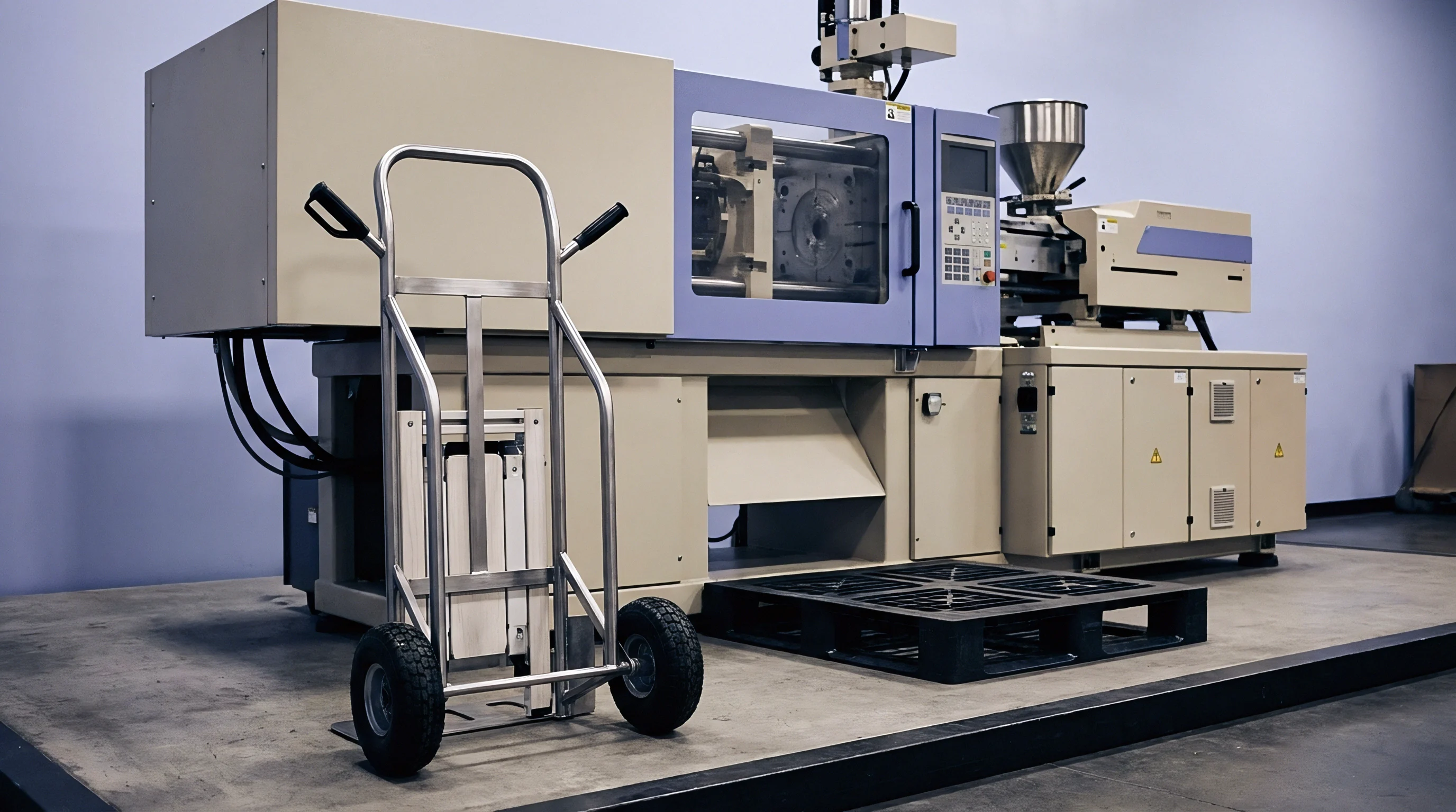
Clamping units supply the force that keeps mold parting lines sealed against melt pressure. Force distribution, platen parallelism, and thermal deflection directly set shutoff wear rates. Incorrect clamp tonnage or misaligned platens accelerate tool damage by concentrating hundreds of tons on small shutoff sections while adjacent areas remain unsealed.
Hydraulic actuators apply concentrated force behind backing plates, flexing machine platens out of flat. Center-push hydraulic rams bow platens outward, creating high force around mold perimeters while relaxing pressure at the center. Toggle clamps pull near tie-bar corners, flexing platens in the opposite direction.
Either way, platen bowing forces mold plates to bend, crushing outer shutoff lands while central cavities flash.
Thermal gradients across press platens warp parting flatness during continuous operation. Heat from oil channels, water manifolds, and hot runners leaks into platens, creating temperature differentials between mounting surfaces and machine frames. Uneven thermal expansion causes shutoff misalignments up to 0.05 millimeters per meter, driving severe scuffing along shutoffs as the mold locks up.

Platen Deflection and Thermal Plate Expansion
Optimizing clamp tonnage protects shutoffs from unnecessary mechanical stress. Processors often crank presses to maximum clamp tonnage assuming it stops flash, but over-clamping crushes shutoff lands and speeds up plastic deformation. Sizing clamp tonnage to actual projected cavity area and packing pressure avoids steel overload.
Equalizing tie-bar strain keeps clamping force symmetric across parting surfaces. Uneven tie-bar tension tilts platens at lockup, driving sharp angular impacts onto mold shutoffs. Ultrasonic strain gauges measure elongation across all four tie bars at full clamp stroke; balancing tension within a two percent window prevents corner crushing on multi-cavity tooling.
Reviewing press configuration parameters before running production tooling ensures balanced shutoff load distribution:
- Platen Parallelism Mapping verifies alignment between stationary and moving platens under full clamp tonnage using dial indicators and laser tools.
- Dynamic Tonnage Calibration checks hydraulic pressure against strain gauge readings to prevent overloading sensitive mold lands.
- Tie-Bar Strain Balancing adjusts tie-bar lock nuts until individual bar tensions stay within a two percent window under load.
- Platen Thermal Insulation places high-strength composite plates between mold bases and press platens to restrict heat transfer and limit platen warping.
Applying clamp force beyond what cavity sealing requires accelerates steel fatigue without improving part quality.

Schedule
Preventative maintenance relies on statistical wear tracking to schedule tool pulls before flash causes unplanned downtime. Fixed stroke count schedules tend to pull molds prematurely or run them past the brink into catastrophic shutoff failure. Intervening at measured statistical thresholds maximizes production run length while protecting expensive inserts from permanent hobbing.
Tool steel selection dictates how well shutoffs stand up to wear. Pre-hardened steels like AISI P20 machine easily but hob quickly under heavy clamping. Slag-remelted AISI H13 hardened to 52 HRC offers strong toughness and fatigue resistance for general production.
Powder metal steels like CPM 10V or high-chromium stainless steels provide dense microstructures that resist abrasive filled resins over millions of strokes.
Physical vapor deposition (PVD) coatings boost shutoff wear life by raising surface hardness. Thin ceramic coatings of titanium nitride or chromium nitride reach micro-hardness values above two thousand Vickers, boosting scratch resistance without altering grinding tolerances. Diamond-like carbon coatings drop friction, preventing fretting galling along sliding shutoffs and interlocks.

Tool Steel Hardness and Coating Performance
Refacing worn parting lines requires grinding away damaged surface steel to restore flat shutoff lands. Precision surface grinding removes metal in passes down to two micrometers, avoiding thermal micro-cracking in hardened steel. Toolmakers grind core and cavity lands simultaneously on dedicated fixtures to keep stack-up heights identical across mold components.
Laser cladding rebuilds heavily eroded shutoff lands without annealing adjacent tool steel. A focused laser melts fine steel powder onto worn edges, depositing dense metal tracks that match base steel chemistry. The tiny heat-affected zone prevents thermal distortion in nearby cavities, and post-weld grinding brings shutoff height back within five micrometers of original drawing dimensions.
PVD chromium nitride coatings maintain shutoff edge geometry up to three times longer than bare H13 steel when running glass-filled polymers.
Tool maintenance requires keeping detailed records of steel loss, welding repairs, and grinding history across the life of the mold.
| Wear Indicator State | Flash Measurement | Statistical Trigger | Toolroom Action | Expected Tool Downtime |
|---|---|---|---|---|
| Baseline Bed-In | < 5 micrometers | Within 1 Sigma Limits | Visual Inspection Only | 0 Hours (In-Press) |
| Early Edge Rounding | 5 – 15 micrometers | Breach 2 Sigma Limit | Parting Face Stone Polish | 2 Hours (In-Press) |
| Moderate Land Erosion | 15 – 30 micrometers | Breach 3 Sigma Warning | Precision Land Kiss-Grind | 16 Hours (Toolroom Pull) |
| Severe Local Hobbing | 30 – 50 micrometers | Breach Upper Action Limit | Laser Cladding & Regrind | 40 Hours (Toolroom Pull) |
| Terminal Land Collapse | > 50 micrometers | Out of Specification | Insert Replacement | 96 Hours (Toolroom Pull) |
Standard quality documentation must contain complete tool wear histories to support warranty claims and transfer audits:
- Initial Baseline Metrology Report records shutoff land topography scans taken before initial tool sign-off.
- Statistical Process Control Trend Logs archives subgroup averages, range charts, and capability metrics collected during production runs.
- Toolroom Intervention Records details steel removal depths, laser welding wire chemistries, and post-repair grinding dimensions for every bench event.
- Molded Sample Sectioning Dossier contains optical micrographs of sectioned flash samples validating root geometry against land edge condition.
Tool purchase contracts often mandate that suppliers maintain parting land capability indices above 1.33 through the first million strokes or absorb all refacing costs.


Yield
Managing parting line wear links tool metrology directly to production costs and capital efficiency. Running worn tooling drives secondary expenses ~ manual deflashing, higher scrap rates, sorting labor, and press downtime. Using SPC to track shutoff wear turns maintenance from a reactive emergency into a predictable line item.
Scrap costs climb rapidly once shutoff wear passes critical flash thresholds. Minor initial flash forces operators to trim parts manually, lengthening cycle times and adding labor costs. Worse flash requires offline trimming fixtures or cryogenic tumbling, adding unit cost to finished parts.
Once flash exceeds print tolerances, parts are scrapped outright ~ wasting resin, press power, and machine capacity.
Tooling amortization models build in preventative refacing cycles to project total tooling cost per part. Spending five thousand dollars on a planned kiss-grind extends mold life by five hundred thousand strokes ~ adding just one cent per part in capital cost. Letting shutoffs degrade into structural hobbing damages core and cavity inserts beyond repair; replacing those inserts costs fifty thousand dollars and adds ten cents per part to landed costs.

Scrap Generation Rates versus Refacing Expense
Tracking parting shutoffs on a 32-cavity connector tool over one million strokes allowed two scheduled kiss-grind maintenance events totaling eight thousand dollars. This proactive approach kept total part scrap under 0.1 percent for the entire campaign, saving an estimated forty-five thousand dollars in resin and press time.
Tool ownership contracts determine who pays for shutoff wear maintenance ~ the OEM or the contract molder. Buyer-owned asset contracts usually assign normal wear maintenance to the buyer, while molders cover damage from improper operation or excessive clamping. Implementing statistical wear tracking provides objective metrology data that separates natural steel wear from operational abuse, resolving invoice disputes.

Capital Amortisation and Tooling Ownership Risk
Auditing toolroom maintenance logs often turns up unrecorded manual stoning. Stoning shutoff edges by hand rounds off sharp corners prematurely, speeding up flash emergence while corrupting baseline metrology tracking records.
Protecting tooling assets during plant transfers requires clear transfer protocols. Shipping a mold without baseline metrology and wear records leaves asset owners vulnerable to disputes over pre-existing shutoff damage. Standardized wear dossiers ensure clean handoffs and protect tooling investments across global supply chains.