Automated Part Rejection Mechanisms Driven by Real Time in Mold Cavity Pressure Telemetry Sensors
Real-time mold cavity pressure telemetry triggers automated mechanical part rejection, ensuring sub-gram defective melt profiles never enter production inventory.


Signal
Cavity pressure telemetry relies on quartz piezoelectric elements positioned within the tool structure to record real-time force transmission. When molten polymer enters the impression, mechanical force acts upon an ejector pin or direct-contact diaphragm. This force compresses quartz crystals inside the sensor, generating an electrical charge proportional to applied pressure.
The electrical charge, measured in picoCoulombs per Bar, travels through shielded low-noise cabling to an external charge amplifier. Data acquisition cards sampling at rates from 1000 Hz to 5000 Hz convert these analog charge signals into digital pressure-time curves.
Indirect piezoelectric sensors sit beneath ejector pins inside the ejector plate assembly, where force travels from the polymer melt through the pin to the sensor button. Ejector pin fit directly affects signal accuracy: a pin bound by carbonized polymer residue or overly tight toolroom clearance dampens force transmission, causing the sensor to record lower peak pressures than the cavity actually experiences. Direct-contact transducers eliminate pin friction altogether by placing a hard-coated diaphragm flush with the cavity wall ~ a practical choice for optical components and thin-wall packaging where surface marks from ejector pins are unacceptable.
Sensor installation requires precise machining of the mounting pocket to prevent transducer face recession, which creates flash, or protrusion, which leaves permanent witness marks on molded parts.

Piezoelectric Sensor Mounting behind Ejection Pins
Pin selection dictates telemetry fidelity in indirect installations. Standard ejector pins deform under high injection forces, introducing bending vectors that distort axial pressure readings. Toolmakers grind sensor pin support heads flat within 0.005 millimeters of parallelism to maintain perpendicular contact against the piezoelectric element.
Sensor pockets housed in the backplate receive hardened support pillar backing to prevent mold base deflection during high-tonnage clamping.
Strain gauge transducers offer an alternative to quartz crystals by utilizing resistive foil bridges bonded to a deflecting diaphragm. Wheatstone bridge circuits output millivolt signals directly, eliminating the requirement for specialized charge amplifiers. Strain gauge sensors exhibit lower temperature limits than quartz elements.
Polymer melt temperatures exceeding 300 degrees Celsius induce thermal drift in strain gauge bridges, requiring continuous software compensation. Quartz sensors withstand cavity wall temperatures up to 200 degrees Celsius and melt contact temperatures exceeding 400 degrees Celsius without signal distortion.
| Sensor Technology | Maximum Temperature Limit | Sampling Frequency Range | Signal Conditioning Hardware | Primary Failure Mode |
|---|---|---|---|---|
| Quartz Piezoelectric (Indirect) | 200 °C Wall Temp | 1000 Hz to 5000 Hz | External Charge Amplifier | Ejector Pin Friction Dampening |
| Quartz Piezoelectric (Direct Melt) | 400 °C Melt Temp | 1000 Hz to 5000 Hz | External Charge Amplifier | Diaphragm Abrasion from Glass Fillers |
| Piezoresistive Strain Gauge | 150 °C Wall Temp | 500 Hz to 2000 Hz | Direct Millivolt Interface | Thermal Drift under Cyclic Heating |
| Fiber Optic Interferometric | 350 °C Melt Temp | 2000 Hz to 10000 Hz | Optoelectronic Signal Unit | Cable Fiber Fractures during Tooling Maintenance |

Direct Melt Contact Transducer Dynamics
Diaphragm wear alters transducer calibration over extended production runs. Highly filled polymers containing 30 percent to 50 percent short glass fibers erode the front face of direct melt sensors. A worn diaphragm shifts baseline charge output, causing false injection peak signals.
Tooling maintenance schedules mandate microscopic inspection of sensor faces every 50,000 cycles to verify front-face integrity.
Amplifier selection governs real-time signal processing capability. Modern digital charge amplifiers execute drift compensation between injection cycles by resetting the charge integrator to zero when the mold opens. Reset timing aligns with press sequence signals to prevent baseline shifting caused by ambient electrical noise or thermal cycling of the mold base.
The amplified voltage signal enters an industrial programmable logic controller via real-time Ethernet protocols, completing signal conversion within two milliseconds of raw charge emission.
Cavity pressure acquisition rates operating below 1000 Hz fail to capture short-shot pressure spikes occurring within a 4-millisecond filling window.
Cabling infrastructure inside the tool base remains vulnerable to mechanical damage during tool assembly and disassembly. High-temperature coaxial cables routed through milled channels require protective armor conduit to withstand crushing forces from mold plates. Wiring junction boxes mounted on the non-operator side of the mold base must isolate sensor connections from cooling fluid leaks and hydraulic oil vapor present in press environments.
Automated part rejection failures attributed to electrical grounding noise or ground loops are often caused by mechanical cable damage. Inspection of tool bases frequently reveals unarmored sensor cables pinched between the core plate and riser block during maintenance.


Chute
Physical rejection hardware executes automated part segregation before the molding cell drops parts onto a bulk storage conveyor. Telemetry controllers process peak cavity pressure and pressure integral calculations while the part cools inside the closed mold. If a single telemetry parameter breaches programmed tolerance limits, the controller sends an immediate digital output signal to the press automation system before clamp opening begins.
Pneumatic diverter mechanisms installed below the mold platen redirect falling parts into scrap bins. High-speed double-acting pneumatic cylinders actuate diverter flaps within 50 milliseconds of receiving a reject signal. The diverter flap stays in the rejection position until optical sensors confirm part passage, preventing misrouted parts from re-entering the good production stream.

Pneumatic Diverter Gate Response Times
Pneumatic solenoids mounted close to diverter cylinders minimize air line lag. Solenoids operating at 6 bar compressed air pressure achieve mechanical switching speeds necessary for rapid cycle injection molding. In multi-cavity tooling running cycle times below three seconds, mechanical diverter flaps lack sufficient response time to segregate parts on a cycle-by-cycle basis.
These fast-cycling systems utilize blowing nozzles that blast defective parts out of the falling path using compressed air pulses timed to cavity ejection.
Robotic end-of-arm tooling provides absolute part segregation in automated cell environments. Linear or six-axis articulated robots extract parts directly from core pins before mold closure. The robot controller receives cavity pressure pass-fail validation signals over fieldbus networks prior to gripper actuation.
Compliant parts land on cleanroom conveyors, while rejected parts travel to a dedicated scrap grinder chute. Robotic drop-gates eliminate downstream part damage caused by free-fall ejection.

Robotic End of Arm Segregation Mechanics
Vacuum pressure switches on robotic end-of-arm tooling verify part retention during extraction. If cavity pressure telemetry indicates a short shot, the robot controller adjusts gripper suction sequences to account for missing wall geometry. Partial fill conditions often prevent vacuum cups from forming a complete seal, causing manual cell faults if automation logic fails to accommodate short-shot physical geometry.
Defect classification dictates physical routing logic inside automated cells:
- Solenoid Response Delays caused by unlubricated pneumatic valves permit defective moldings to slide past diverter flaps into finished goods bins.
- Mechanical Flap Jamming results from flash wedged between moving diverter plates and fixed housing frames, halting automated cell operation.
- Vacuum Cup Retention Failure occurs when short-shot part warpage prevents complete seal formation on robotic extraction grippers.
- Optical Verification Sensor Mismatch generates false reject alarms when airborne dust blocks photoelectric light curtains inside drop chutes.
Direct part diversion at the press platen prevents downstream contamination of good inventory bins.
Part segregation systems operating beneath multi-cavity tools require dedicated drop lanes matched to specific mold cavities. Segmented divert chutes use individually controlled flaps for each cavity column. When cavity three experiences a transducer failure or pressure spike, its corresponding chute segment opens to scrap while adjacent compliant cavity lanes continue depositing parts onto production conveyors.
A jammed diverter flap directing out-of-spec polyarylamide housings into compliant inventory resulted in a 14,200 USD loss. The pneumatic solenoid suffered internal seal degradation over 800,000 cycles, extending flap actuation time from 45 milliseconds to 120 milliseconds. Parts ejected from the mold bounced off the edge of the delayed flap, tumbling directly into box containers intended for assembly line delivery.

Integral
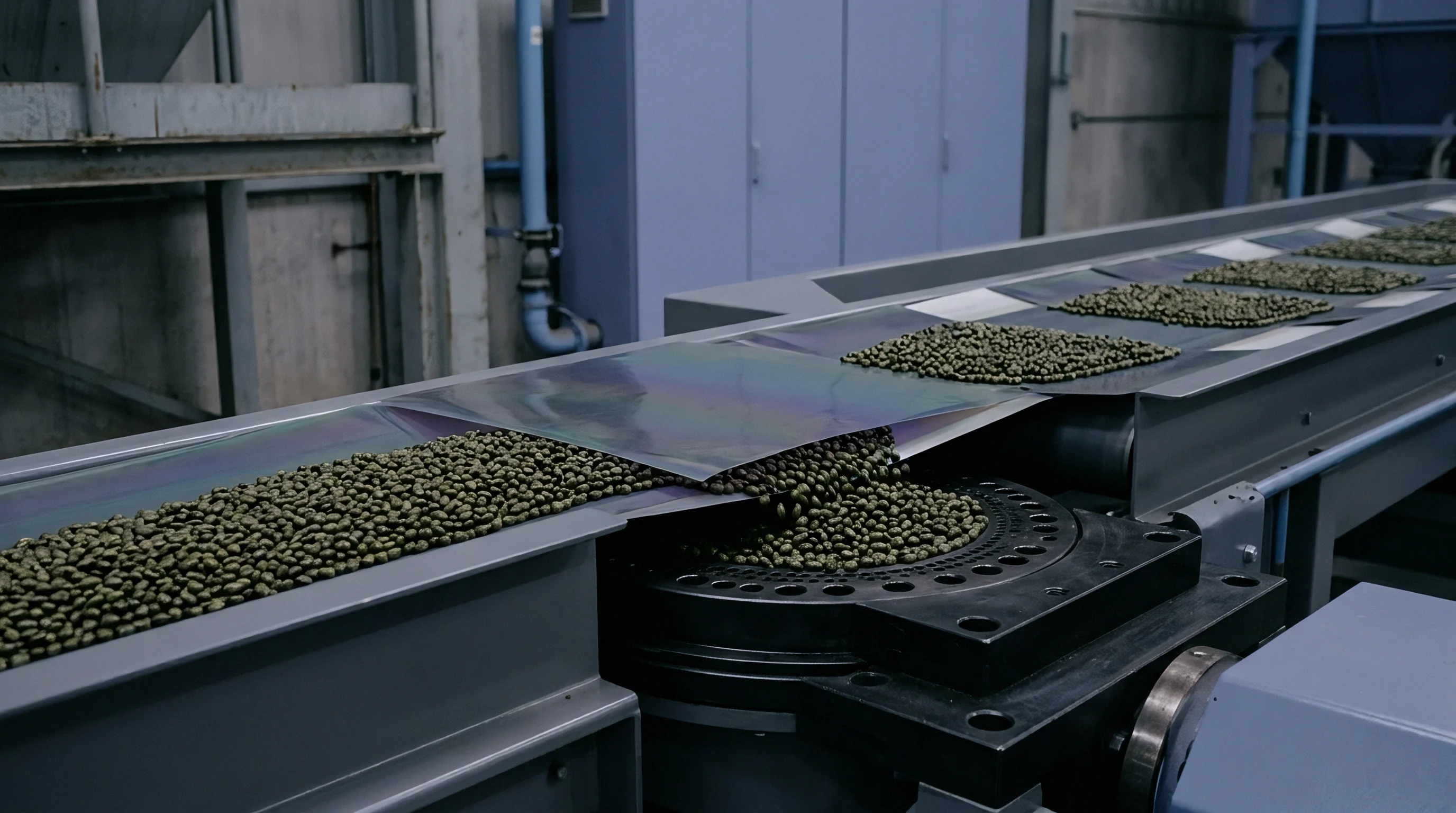
Real-time algorithms process cavity telemetry by monitoring curve envelopes across fill, transfer, pack, and hold phases. The primary mathematical metric evaluated for automated part rejection is the cavity pressure integral, calculated as the area under the pressure-time curve from the instant polymer contacts the sensor diaphragm until cavity gate freeze occurs. The pressure integral correlates directly to volumetric shrinkage, part weight, and final dimensional tolerances specified under DIN 16742 standards.
Peak cavity pressure represents the maximum force recorded during the filling and packing cycle. A sharp peak pressure drop indicates a short shot caused by shot-size variation, barrel thermal degradation, or nozzle freeze-off. Conversely, an excessively high pressure peak signals cavity overpacking, leading to part flash, severe internal stress, and ejection mold sticking.
Algorithmic window limits define upper and lower boundary thresholds around baseline curve profiles established during scientific mold trials.

Which Telemetry Deviations Demand Instant Mechanical Segregation?
Piezoelectric charge output decaying mid-cycle triggers immediate pneumatic gate switching. Viscosity fluctuations inherent to regrind utilization alter melt resistance during cavity filling. Higher melt viscosity increases pressure drop across the runner system, delaying cavity filling and reducing the pressure integral.
Lower melt viscosity allows faster filling, producing early pressure spikes that breach upper envelope limits.
Decoupling point evaluation checks hydraulic machine pressure against cavity telemetry at the precise moment velocity control transfers to pressure control. If cavity pressure fails to reach target values at velocity switchover, the controller flags the cycle as a transfer fault. Screw cushion instability directly manifests as cavity pressure integral variance.
A cushion variation exceeding 0.5 millimeters disrupts pack phase density, changing mechanical properties of structural moldings.
| Parameter Metric | Target Nominal Value | Upper/Lower Tolerance Limit | Algorithm Sampling Window | Automated Rejection Trigger Delay |
|---|---|---|---|---|
| Peak Cavity Pressure | 650 Bar | ± 25 Bar | Peak Search (Fill/Pack Boundary) | 2 Milliseconds |
| Cavity Pressure Integral | 4200 Bar-Seconds | ± 150 Bar-Seconds | Switchover to Gate Freeze | 5 Milliseconds |
| Melt Front Velocity Signal | 120 mm/sec | ± 10 mm/sec | Sensor 1 to Sensor 2 Transit | 1 Millisecond |
| Pack Phase Cooling Slope | -45 Bar/sec | ± 5 Bar/sec | Hold End to Mold Open | 10 Milliseconds |
| Data acquired during qualification trials of 30% glass-filled polybutylene terephthalate on a 200-ton electric press. | ||||

Pressure Integral Calculation across Fill and Pack Phases
Real-time rejection logic requires sequential calculation execution during machine operation:
- Acquire piezoelectric charge signal at 2000 Hz throughout the injection stroke.
- Compute real-time curve area from switchover point to end of hold pressure.
- Compare target envelope values against upper and lower specification limits.
- Transmit rejection pulse to machine programmable logic controller within five milliseconds.
- Actuate physical divert gate before mold opening sequence begins.
Cooling rate slope evaluation provides insight into mold wall thermal management. After holding pressure terminates, cavity pressure decays as polymer melt shrinks away from cavity walls. The slope of this pressure drop reflects heat transfer efficiency through cooling channels.
A sudden reduction in cooling slope indicates scaling or blockage inside mold cooling lines, elevating part temperature at ejection and causing post-mold warpage.
Data processing hardware must complete integral mathematical routines before the press signals clamp opening. Fast-cycling medical applications demand completion of digital filtering, curve alignment, integral calculation, and rejection decision logic within a ten-millisecond processing window. Modern embedded microprocessors handle these operations using hardware-accelerated floating-point units integrated directly into press control cabinets.
Rapid drops in melt viscosity immediately alter cavity fill dynamics and baseline pressure thresholds.
The operational dispute centers on how rapidly adaptive envelope limits should adjust to changing environmental conditions without masking real processing defects. If an adaptive algorithm automatically widens acceptable pressure integral boundaries to accommodate ambient factory temperature shifts, subtle dimensional drift in semi-crystalline polymers will pass automated inspection, yielding out-of-spec shipments to end-user assembly plants.


Manifold
Multi-cavity injection molds deploy individual transducers in every impression to monitor cavity-to-cavity flow imbalance. In a 32-cavity tool, subtle differences in runner length, hot runner nozzle temperature, or gate wear alter melt distribution across impressions. Cavity pressure telemetry identifies specific failing impressions in real time, preventing a single defective cavity from corrupting an entire shot batch.
Evaluating multi-cavity tools requires independent cavity routing. Individual telemetry channels continuously stream data to multi-channel acquisition modules. If cavity twelve experiences a clogged gate resulting in a short shot, the telemetry system registers a low pressure integral for that specific channel while recording compliant profiles for remaining cavities.
Automated rejection mechanisms must process single-cavity drop commands or flag the whole shot depending on downstream automation capabilities.

Cavity-Specific Telemetry in Multi-Cavity Tooling
Hot runner valve gate tools offer precise control by linking cavity telemetry directly to individual pneumatic or servo valve gate actuators. Sequential valve gating utilizes cavity pressure signals rather than screw position to open and close valve pins. As melt fills cavity one and reaches the target pressure threshold, the controller fires the solenoid valve to open the gate for cavity two.
This real-time pressure-driven gating eliminates weld line defects and ensures identical volumetric filling across complex multi-gated parts.
Valve gate shutoff mechanisms can isolate defective cavities mid-cycle. If a dedicated sensor records abnormal pressure escalation during early fill phase, the control system sends an immediate signal to close that cavity’s pneumatic valve pin. Shutting the valve pin prevents further melt entry, protecting the cavity from severe overpressurization and flash while allowing remaining cavities to finish their packing cycle normally.

Valve Gate Shutoff Isolation versus Downstream Segregation
Cavitation isolation decision protocols govern hardware layout selection:
- Cavity Count Thresholds dictate whether physical sorting chutes or individual valve gate shutoff mechanisms yield lower total tooling expenditures.
- Valve Gate Actuation Speed limits shutoff effectiveness during high-speed injection of thin-wall packaging parts.
- Part Separation Geometry determines if robotic end-of-arm tooling can drop rejected individual cavity moldings into separate scrap bins while saving compliant cavities.
DIN 16742 Molded Part Tolerance Group TG4 enforces strict boundary limits on volumetric shrinkage that telemetry sensors detect prior to part ejection.
Part tracking becomes challenging when multi-cavity tools drop parts onto single output conveyors. Without cavity-segregated sorting chutes, a defective part detected in cavity seven forces downstream automation to reject the entire 32-part shot. This whole-shot scrap penalty dramatically increases production costs, particularly when processing expensive engineering resins like polyetheretherketone or polysulfone.
Quality standard compliance mandates strict data traceability for multi-cavity telemetry systems. Standard ISO 20457 Section 6.3 mandates archive retention of cavity-specific process parameters for critical safety components. Molders handling automotive brake components or medical device housings must archive real-time pressure curves matched to unique cavity numbers for ten years post-production, establishing clear legal liability records in product defect litigations.

Drift
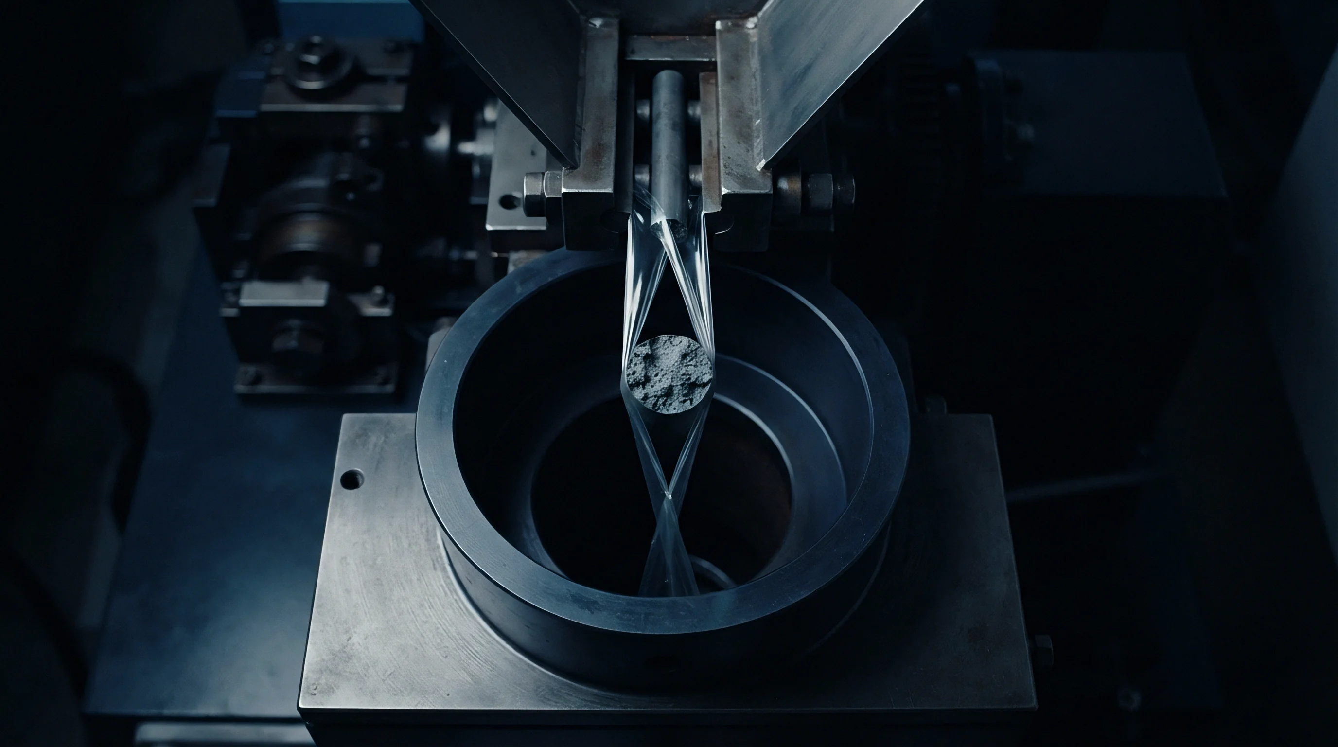
Continuous heat exposure alters sensor sensitivity coefficients over extended production runs. Thermal expansion of mold plates changes mechanical preload forces applied to indirect piezoelectric sensors. A tool operating at 140 degrees Celsius oil temperature expands differently than when sitting cold at 20 degrees Celsius ambient room temperature.
This thermal shift changes baseline electrical charge output, producing artificial calibration offsets.
During tool bring-up, baseline zero-point drift occurs when thermal gradients across mold plates generate uneven mechanical stress on quartz element housing shells. Digital charge amplifiers correct zero-point drift by executing automated reset commands between clamp opening and closing sequences. Cable insulation resistance degradation presents another source of signal drift.
Moisture intrusion into coaxial cable connectors reduces insulation resistance below 10 to the 13th power Ohms, causing charge leakage to ground and inaccurate pressure attenuation.

Thermal Expansion Effects on Sensor Calibration
Piezoelectric crystals undergo reversible thermal expansion that alters their charge output constant. Quartz sensors lose approximately 0.02 percent of sensitivity per degree Celsius increase in operating temperature. High-temperature telemetry applications utilize specialized piezoceramic elements, such as Gallium Phosphate crystals, which maintain constant sensitivity coefficients at temperatures reaching 400 degrees Celsius.
Mechanical wear on sensor pin tips alters signal transmission efficiency. Over hundreds of thousands of cycles, continuous contact between polymer melt and ejector pin faces causes micro-abrasion. Pin tip erosion creates a radius on pin edges, allowing polymer melt to seep into clearance gaps.
Material flashing around the pin increases friction against the mold cavity hole, dampening force transfer to the sensor and yielding falsely low cavity pressure signals.
| Polymer Chemistry | Processing Melt Temp | Mold Wall Temp | Uncompensated Drift Rate | Required Recalibration Interval |
|---|---|---|---|---|
| Unfilled Polypropylene (PP) | 230 °C | 40 °C | – 0.4 % per 100k cycles | 500,000 Cycles |
| 30% Glass Polybutylene Terephthalate (PBT) | 260 °C | 80 °C | – 1.2 % per 100k cycles | 250,000 Cycles |
| Polyarylamide (PARA) | 280 °C | 130 °C | – 2.8 % per 100k cycles | 100,000 Cycles |
| Polyetheretherketone (PEEK) | 380 °C | 180 °C | – 4.5 % per 100k cycles | 50,000 Cycles |
| Summary: High thermal profiles and abrasive fillers accelerate transducer drift rates, requiring shortened physical recalibration schedules. | ||||

Piezoelectric Charge Amplifier Zero-Point Shift
Software algorithms combat drift by implementing dynamic window tracking. Dynamic tracking recalculates baseline moving averages over a rolling sample of 50 compliant cycles. If baseline cavity pressure shifts gradually due to ambient mold temperature variations, software adjusts rejection threshold envelopes accordingly.
Dynamic adjustment must enforce hard stop limits to prevent software from absorbing genuine tool wear or heater band failures into recalculated baseline averages.
Periodic recalibration of sensors ensures baseline readings remain accurate across long production runs.
Archived telemetry curves provide an objective record for verifying process consistency over time.
Cold tool conditions distort baseline pressure readings before thermal equilibrium is reached.
Baseline pressure calibration checks performed cold yield invalid operational thresholds for thermal equilibrium production.

Stipulation
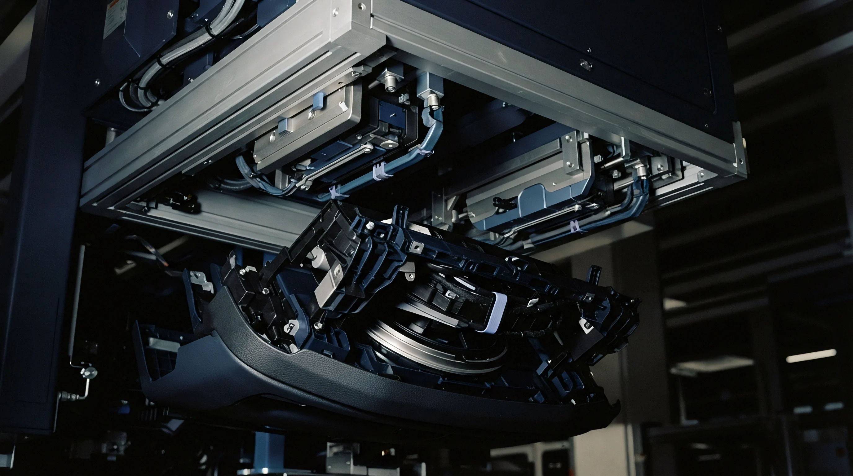
Procurement agreements governing high-cavitation tooling draw explicit lines defining telemetry equipment ownership, sensor placement standards, and scrap attribution. Tooling buyers committing capital to automated production lines specify sensor brand, model, cable routing, and amplification hardware directly within tooling build standards, while sensor pin clearance tolerances are specified directly on the tool assembly drawing.
Sensor integration adds initial tooling cost while reducing long-term piece price by preventing non-compliant parts from reaching assembly lines. Retrofitting telemetry sensors into existing tooling costs significantly more than integrating sensor pockets during initial CAD mold design stages. Milled cable channels, junction box mounts, and hardened backplate support pillars require precise machining best performed during initial mold plate production.
Tooling Procurement Clauses for Telemetry Hardware
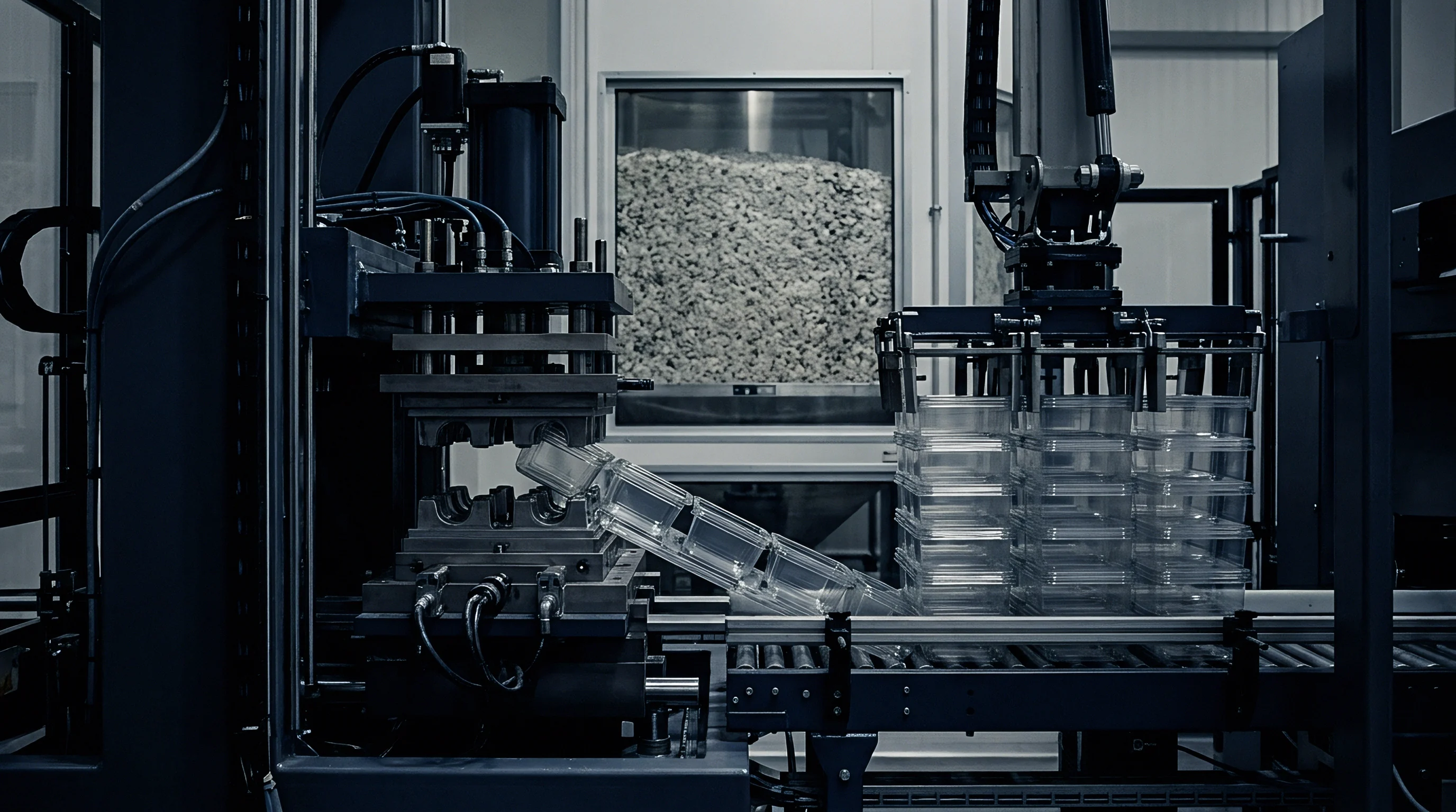
Scrap attribution clauses protect buyers from paying piece-price margins on parts rejected by telemetry systems. Procurement contracts mandate that molders absorb material and machine-hour costs for parts ejected via automated rejection mechanisms. When scrap rates breach agreed baseline allowances, contract clauses require molders to audit thermal windows, check gate wear, and recalibrate telemetry hardware at moulder expense.
False positive rejections increase production costs by discarding structurally sound parts. If telemetry rejection thresholds are set too narrow, normal process noise triggers false pneumatic diverter switching, wasting good material. False negative errors carry higher financial liabilities, as defective parts shipped to end customers trigger assembly line shutdowns, sorting penalties, and recall expenditures.
Tool modifications for sensor pocket retrofits compromise cooling circuit layout when executed without thermal FEA validation.

Commercial Allocation of Scrap Costs from False Rejections
Contractual documentation for tooling telemetry mandates explicit inclusion of specific technical exhibits:
- Transducer Specification Sheets defining individual sensor serial numbers, factory charge sensitivities, and maximum operating temperature parameters.
- Pneumatic Diverter Maintenance Records logging solenoid valve replacement intervals, cylinder cycle counts, and optical sensor cleaning schedules.
- Acceptable Scrap Threshold Clauses establishing maximum allowable percentages for telemetry-driven part rejections before commercial reviews occur.
Undetected part defects directly increase material waste and secondary processing costs.
Optimizing injection cycle times protects profit margins in high-volume molding operations.
Cavity pressure drops immediately upon loss of melt feed or gate freeze-off.
Scrap costs accumulate rapidly when unverified parts pass into finished inventory.
Commercial tooling quotes must itemize telemetry system components separately from mold base, hot runner, and cavitation costs. Sensor replacement provisioning requires stocking spare transducers, pin assemblies, and high-temperature signal cables press-side. Maintaining spare parts inventory prevents extended press downtime when a sensor diaphragm fails or a cable pinches during routine tool maintenance.
Quality agreements specify joint tool sign-off protocols based on cavity pressure telemetry validation. Tool acceptance requires running a continuous 24-hour capability study demonstrating scrap rates under 0.5 percent while operating under full real-time telemetry part rejection logic. Final tooling payments remain linked to successful completion of these capability trials, ensuring that both physical tooling and telemetry automation perform reliably in high-volume manufacturing environments.