Microscopic Air Entrapment Mechanics in Textured Mold Surfaces
Microscopic air entrapment in textured molds stems from rapid melt front advancement trapping gas in surface valleys, manageable via controlled fill rates and porous micro-venting.
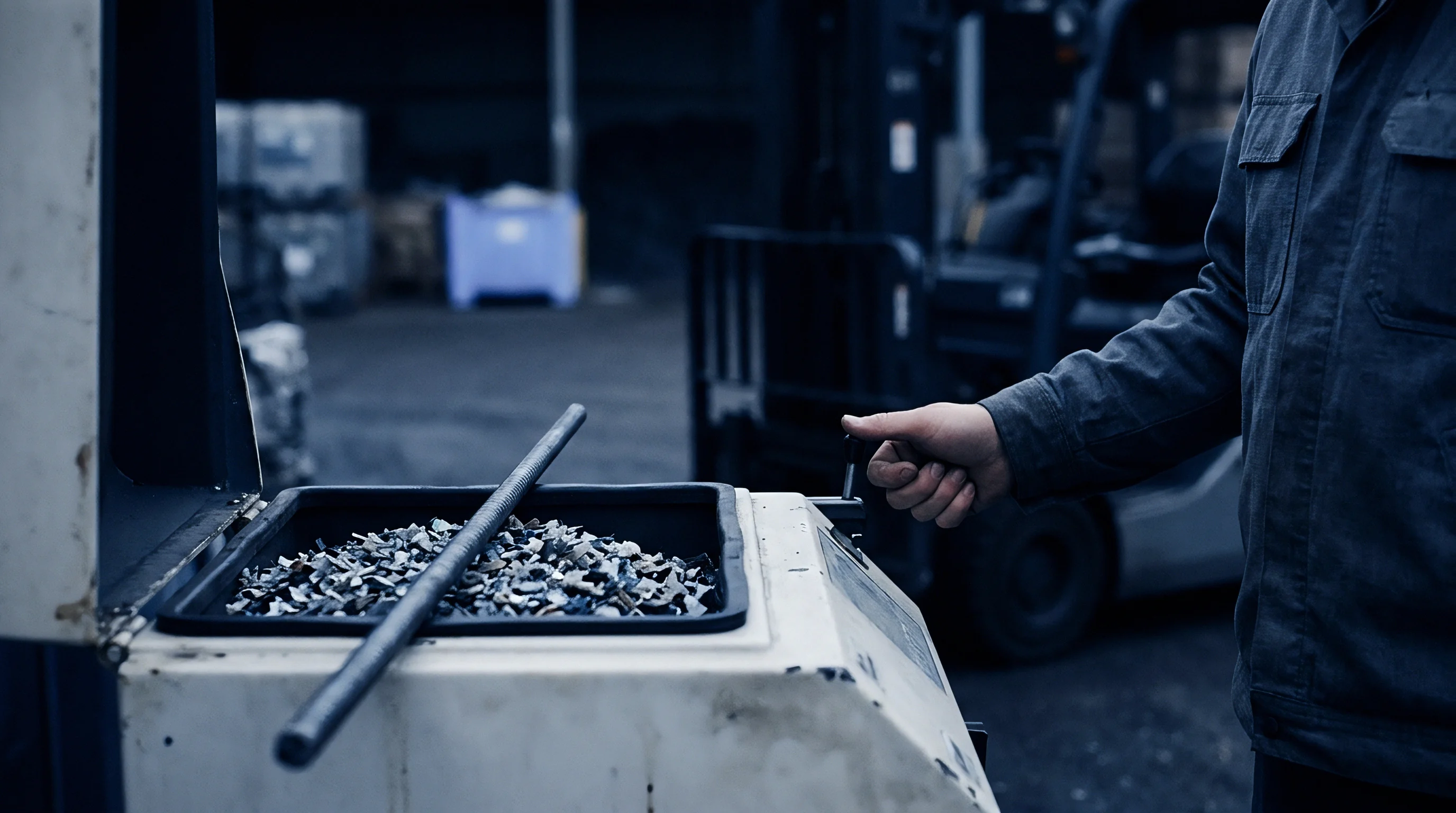


Melt Advancement across Surface Topography
When molten polymer moves across a micro-textured mold cavity wall, its contact dynamics are shaped by surface topography, temperature gradients, and shear rates. The advancing liquid touches the protruding peaks of the texture first. If the resin bridges across these asperities, air inside the cavity gets trapped in the micro-valleys beneath.
While polymer flows over flat steel with minimal drag, textured surfaces present tiny geometric barriers that resist flow, altering the macroscopic contact angle between the melt front and the steel substrate.
Capillary pressure inherently opposes the entry of liquid resin into these narrow topography channels.
The depth and width of surface depressions dictate whether advancing resin wets the steel topography completely or bridges across open voids. Surface tension governs boundary drag. High melt viscosity and high injection speeds make the polymer more likely to skid over valley entrances rather than fill them in sequence.
This bridging creates sealed micro-pockets of trapped air under the polymer skin, where pressure rises rapidly as the melt front compresses the trapped gas against the steel boundary.
Surrounding micro-cavities with high capillary resistance causes molten polymer to bridge across surface valleys before air escapes.
Whether the surface experiences complete wetting or gas entrapment comes down to the balance between dynamic melt pressure and capillary resistance inside the micro-cavities. When hydrodynamic pressure overcomes local capillary resistance, resin drives down to the valley floor and pushes air toward adjacent escape paths. When capillary resistance wins out, the melt bridges the peaks and seals off isolated gas cells.
Cold mold surfaces speed up skin freezing at these peaks, locking the bridged morphology in place before the cavity can fill completely.

Wetting Transitions and Fluid Resistance
The exact form of gas entrapment inside mold textures depends on fluid behavior during injection.
- Cassie-Baxter Air Cushion State occurs when molten resin bridges across neighboring texture peaks, leaving gas trapped in the underlying microscopic valleys.
- Wenzel Penetration Breakdown develops when dynamic cavity pressure forces the polymer front into full contact with the valley floor, driving air pockets toward local parting lines.
- Micro-Pocket Corner Isolation forms at sharp microscopic step edges where high surface tension stops the liquid from penetrating ninety-degree root radii.
- Dynamic Wave Front Enclosure arises when converging micro-flow ribbons trap pockets of gas along secondary merging lines in complex laser textures.
Melt flow inside micro-textured cavities responds directly to local shear rates and wall heat transfer coefficients. High injection speeds raise shear rates, dropping instant viscosity in shear-thinning resins like polypropylene and acrylonitrile butadiene styrene. This drop helps the resin reach narrow valley floors and reduces air cushion formation.
However, excessive injection speeds leave less time for trapped air to escape across parting lines or diffuse through porous steel. Cold mold walls freeze the outer polymer skin within milliseconds of contact, locking micro-voids permanently into the finished part surface.

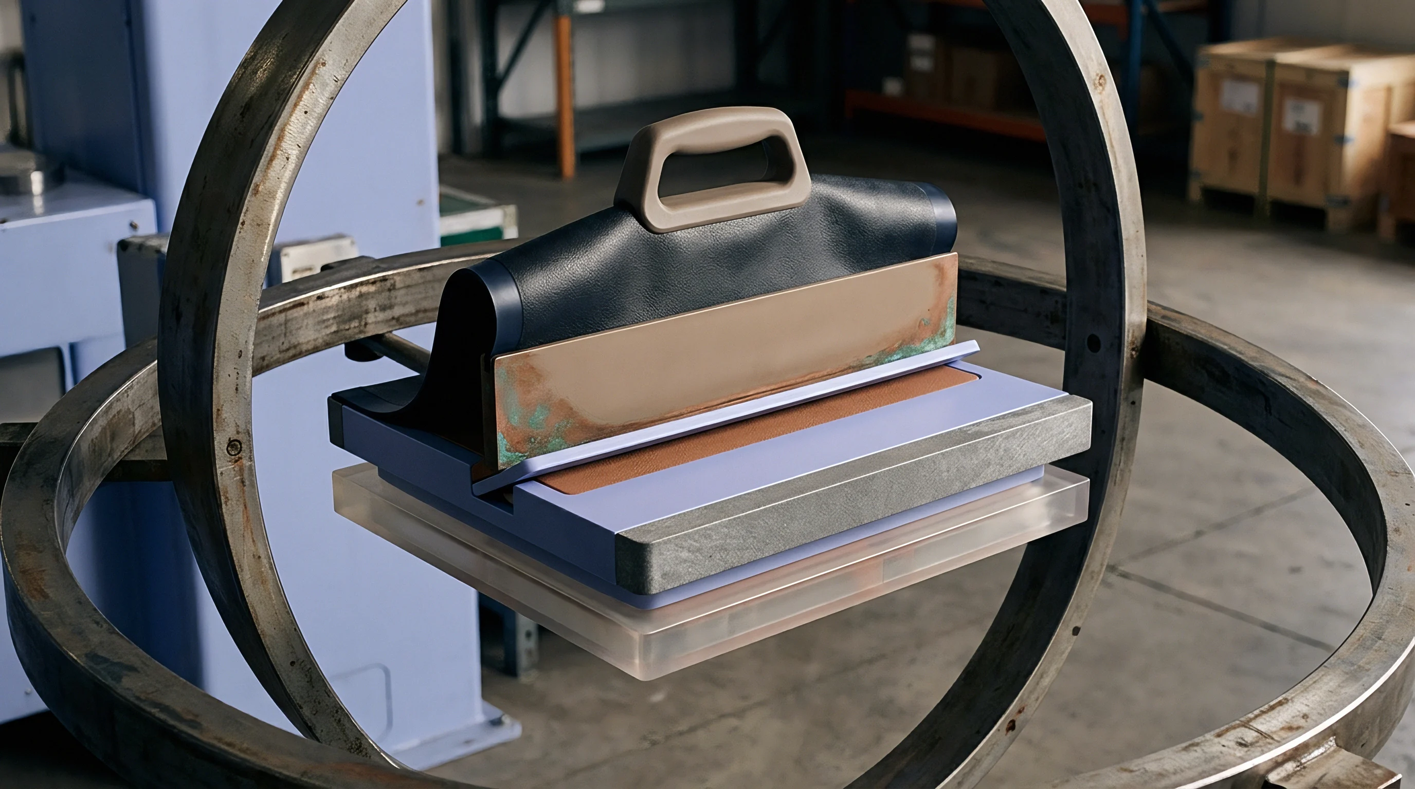
Ignition

Adiabatic Compression Dynamics
When fast injection drives polymer melt against sealed micro-pockets of air, the trapped volume shrinks rapidly, converting mechanical compression energy into intense heat. Because heat cannot transfer into the surrounding tool steel as fast as the volume collapses, the process runs under near-adiabatic conditions. High temperatures within the compressed pocket can then ignite volatile organic compounds driven out of polymer additives and degradation products.
| Compression Ratio | Fill Time Range (s) | Calculated Gas Temp (°C) | Observed Defect Type | Material Surface Response |
|---|---|---|---|---|
| 10 to 1 | 0.20 to 0.50 | 380 to 450 | Gloss Gloss Shift | Localized surface haze without charring |
| 25 to 1 | 0.10 to 0.20 | 550 to 680 | Silver Streaking | Micro-pitting and additive volatilization |
| 50 to 1 | 0.02 to 0.10 | 820 to 1100 | Dieseling Burn Marks | Carbonized resin residue and pit erosion |
| Gas temperatures calculated assuming ambient air temperature of 40°C before compression with an adiabatic index of 1.4 for dry atmospheric gas. | ||||
This rapid adiabatic compression drives sharp local temperature spikes.
Temperature spikes inside compressed gas pockets routinely exceed the thermal degradation limits of engineering thermoplastics. Polycarbonate, polyamide, and polyetheretherketone undergo molecular chain scission when exposed to air trapped above six hundred degrees Celsius. These extreme local temperatures carbonize the resin, leaving dark deposits on the mold wall.
Over long production runs, repeated ignition events erode the textured steel topography, dulling crisp feature edges and enlarging microscopic pits.
A compressed gas pocket reaching fifty atmospheres generates localized temperatures above eight hundred degrees Celsius within two milliseconds of cavity packing.
Trapped gas also physically prevents full melt replication against the steel.
These trapped gas pockets alter local surface luster across the part.
Beyond chemical charring, trapped gas cushions keep molten resin from touching the steel substrate. This lack of contact creates noticeable gloss variations across the part. Areas with solid steel contact reproduce the texture’s true matte finish, while zones affected by micro-air entrapment develop smooth, shiny patches where the polymer skin cooled against compressed gas rather than etched steel.

Thermal Degradation and Pit Erosion
Thermal degradation permanently discolors and breaks down polymer chains.
Entrapped gas inside micro-textured details alters local cooling dynamics. Atmospheric air has a thermal conductivity of roughly zero point zero three Watts per meter-Kelvin, compared to about thirty Watts per meter-Kelvin for tool steel. An air barrier between the melt skin and mold wall thermally isolates the resin, delaying local skin solidification and building uneven shrinkage stresses across the grain boundary.
This imbalance leads to visible sink marks, localized warpage, or ejection distortion when the part clears the tool.
Ignoring adiabatic compression during mold design leads directly to severe tool erosion, visible flaws on cosmetic surfaces, and frequent downtime for manual cavity cleaning.


Vent
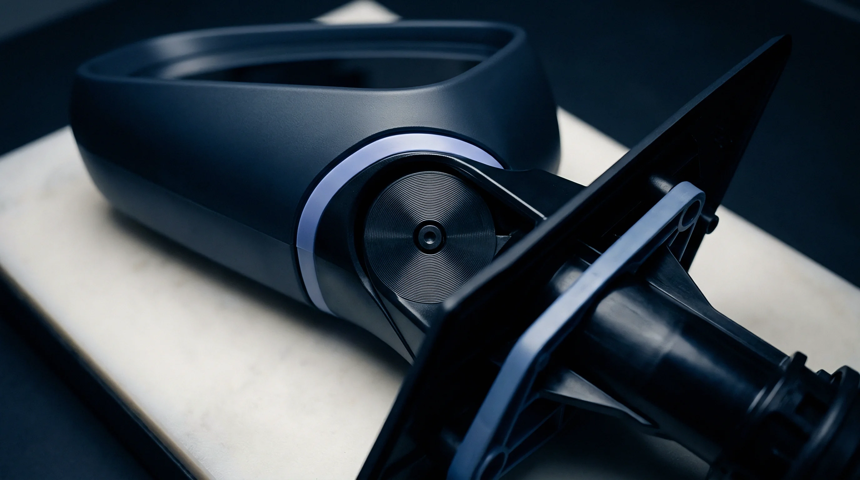
Micro Venting Architecture and Porous Metals
Preventing microscopic air entrapment requires continuous gas escape routes built directly into the textured cavity wall. Standard mold vents are machined into the parting line at depths between ten and thirty micrometers. Micro-textured surfaces need specialized evacuation geometry because pockets form in isolated valleys far from the main parting line.
Running micro-venting channels directly behind textured zones gives compressed air a pathway into secondary collection manifolds.
Standard mold specification DIN 16742 mandates maximum vent depths equal to fifty percent of the polymer resin flash threshold to prevent material seepage under injection pressure.
Porous steel inserts offer an effective path to diffuse trapped gas.
Porous sintered tool steel inserts vent broad micro-textured cavity faces effectively. These inserts feature interconnected internal pores between three and twenty micrometers in mean diameter, letting air escape while stopping high-viscosity molten plastic. Placing porous metal behind laser-textured show surfaces eliminates air cushions, ensuring sharp grain replication across deep draw walls and complex geometric transitions where perimeter vents cannot reach.

Design Checklist for Micro Cavity Venting
Selecting the right venting strategy for textured tool inserts means matching processing parameters against tool steel constraints.
- Porous Sintered Metal Inserts provide uniform surface gas evacuation across textured faces, holding air clearance under four hundred bar packing pressures.
- Peripheral Parting Line Vents release bulk cavity air ahead of the melt front, cut at depths matched to specific resin viscosity limits.
- Ejector Pin Perimeter Micro-Flutes utilize mechanical clearance spaces along movable core pins to vent isolated texture pockets located inside deep rib networks.
- Vacuum-Assisted Cavity Evacuation draws vacuum on sealed mold cavities prior to injection, reducing residual air mass before melt entrance.

Why Do Micro Textured Tool Ribs Trap Gas?
Micro-textured ribs pose severe venting challenges because melt fronts enter the narrow space from opposite sides, trapping air against the closed rib top. The high aspect ratio of these ribs prevents conventional parting line vents from reaching the trapped volume. Gas pinched at the crest cannot pass through solid steel, so the compressed pocket either ignites or pushes back against the advancing polymer.
This resistance leads to short shots, surface burns, and mechanical weakness along the weld line.
In accordance with ISO 20753 tooling guidelines, cavity validation documents must state maximum allowable vent land lengths and micro-porous clearance bounds to enforce tool maintenance schedules before thermal deposit fouling restricts gas permeability.
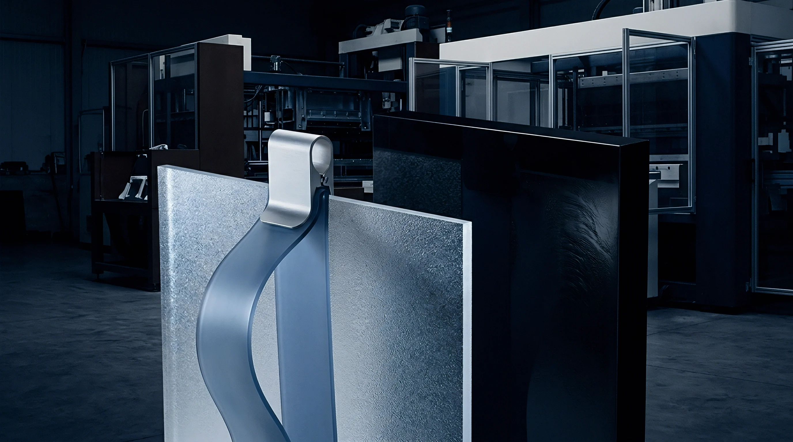

Etch
Topography Metrics and Texturing Methods
The process used to create mold textures dictates the microscopic geometry of the valleys where air gets trapped. Chemical photo-etching uses acid to erode steel left exposed by a photoresist mask, producing rounded micro-pits with smooth transition radii. Five-axis laser ablation uses pulsed fiber lasers to vaporize steel into precise geometry, producing sharp, deep, multi-level patterns.
Electrical discharge machining with graphite or copper electrodes yields stochastic VDI 3400 spark textures with steep micro-craters and undercut edges.
| Texturing Method | Roughness Rz (µm) | Mean Peak Distance Sm (µm) | Valley Aspect Ratio | Micro Air Trap Risk |
|---|---|---|---|---|
| Chemical Photo-Etching | 12 to 45 | 80 to 200 | 0.15 to 0.30 | Low to Moderate |
| 5-Axis Laser Texturing | 5 to 80 | 20 to 100 | 0.40 to 0.80 | High |
| EDM VDI 3400 Erosion | 8 to 63 | 30 to 120 | 0.30 to 0.60 | Moderate to High |
| Polished Mold Steel | 0.1 to 0.8 | N/A | N/A | Negligible |
Pulsed lasers vaporize precise cavity geometries directly into hardened steel.
Highly polished mold steel allows gas to clear the surface cleanly.
Evaluating mold textures requires metrics beyond simple average roughness. Peak-to-valley height, mean peak spacing, and valley root radii all influence air retention. Steep aspect ratios increase capillary resistance, preventing molten resin from reaching the bottom of the texture during fill.
Adding draft to textured cavity walls widens valley openings, making it easier for air to escape and reducing scuffing during ejection.
Texture Specification Procedure
To avoid severe gas entrapment issues on textured parts, tool designers evaluate surface topographies prior to releasing tool drawings for steel cutting.
- Determine the target surface visual requirement and select the corresponding texturing technology based on geometric complexity.
- Calculate the minimum required draft angle by adding one degree of draft per five micrometers of texture depth to prevent scuffing.
- Inspect the 3D surface profile geometry to verify that valley aspect ratios remain below zero point four.
- Establish primary parting line vent placement adjacent to deep texture zones to minimize compressed air paths.
- Integrate vacuum assist channels into the tool design drawing when laser texture depth exceeds forty micrometers.
Micro vents clear trapped gas from cavity boundaries quickly.
The depth of the texture directly dictates the minimum required draft angle.
Tool steel hardness helps prevent vent deformation under high clamping forces.
Gloss variations on initial shots are frequently attributed to improper resin drying or incorrect barrel temperatures, masking underlying micro-air entrapment caused by inadequate valley draft angles inside laser-ablated cavity regions.


Diagnosis
Empirical Methods and Short Shot Analysis
Identifying micro-air entrapment on production parts requires systematic short-shot analysis alongside high-resolution optical surface profiling. During a short-shot trial, injection volume is reduced to seventy percent of part weight and increased in two percent increments. This step-by-step fill mapping isolates where the advancing melt front traps air against textured cavity walls before packing pressure compresses the gas.
Short-shot sequences reveal exact fill front dynamics during cavity loading.
Vacuum assistance evacuates sealed cavity zones before melt entry.
A practical case illustrates the diagnosis process on an automotive interior door panel component measuring three hundred millimeters by two hundred millimeters with a two point five millimeter wall thickness, molded in mineral-filled polypropylene. The tool features a laser-etched geometric grain forty-five micrometers deep. Initial production runs showed severe gloss patches along the outer edge of the textured surface and micro-pitting along secondary flow boundaries.
Systematic root cause analysis proceeded under controlled press conditions.
Injection speed was lowered from fifty millimeters per second to fifteen millimeters per second in five millimeter steps. At higher speeds, trapped air could not clear the grain boundaries in time, driving compression pressure up to fifty-five bar. At fifteen millimeters per second, the gloss patches diminished, but cycle time increased by four point two seconds, making the cell uneconomic.
The core insert was then modified by retrofitting porous sintered steel plugs with a twenty-micrometer pore size directly behind the affected zones.
Physical inspection of short-shot sequences confirms that microscopic air cushions form long before complete cavity volumetric fill occurs.
Higher fill speeds compress trapped air far more aggressively.
After retrofitting, cavity vacuum transducers recorded a pressure drop from atmospheric to zero point two bar before melt arrival. Grain replication improved immediately, with optical profilometry showing texture depth fidelity rise from seventy-two percent to ninety-six percent of the true steel depth. Cycle time returned to the target twenty-two second duration, and gloss variations dropped within the specified range of two point five plus or minus zero point three gloss units at a sixty-degree angle.
Dossier Requirements for Tool Sign-Off
Documenting process capability and tool venting performance requires structured dossier submission prior to final tool acceptance.
- Short-Shot Progression Series provides visual photographic evidence of melt front advancement and identifies air enclosure locations.
- Cavity Pressure Transducer Logs records dynamic pressure curves across fill, pack, and hold phases to verify absence of air back-pressure spikes.
- Surface Profilometry Scans measures optical replica depth against raw mold steel profiles using non-contact laser confocal metrology.
- Thermal Imaging Logs tracks localized surface temperature drops associated with trapped air barriers or adiabatic thermal spikes.
What micro-scale surface energy modifications can permanently reduce capillary resistance inside deep laser-etched cavity valleys without altering the mechanical wear resistance of hardened tool steel?