Calculating Cavity Thermal Contact Conductance for Etched Tool Surfaces
Calculated thermal contact conductance on etched tools drops up to 80 percent during cooling, requiring dynamic pressure modeling to avoid warpage and cycle delays.


Grain
Texturing a flat mould wall converts its surface into a micro-topography of peaks and valleys. When molten polymer meets this cavity boundary during injection, heat flows from the liquid core into the tool steel across a rough interface. Determining thermal contact conductance over an etched tool requires balancing two competing paths: solid contact where polymer touches steel asperities, and heat transfer through stagnant gas trapped within the texture depth.
Across common chemical etch grades from VDI 12 to VDI 36, cavity contact conductance varies significantly throughout the cycle. It rises from roughly 350 W/m²K at initial contact to around 3800 W/m²K at peak packing pressure, before falling back to 250 W/m²K when thermal contraction pulls the interface apart. Trapped gas pockets in an etched cavity reduce peak conductance by 30% to 55% compared to polished steel under equivalent holding pressure.
Establishing accurate boundary conditions is essential for realistic predictions of cooling time, part warpage, and skin freezing kinetics. Standard CAE software often defaults to a constant heat transfer coefficient between 1500 and 3000 W/m²K across the entire cycle. Applying a uniform coefficient to an etched cavity introduces noticeable simulation errors.
Thick wall sections behind textured surfaces retain heat longer than standard software predicts because trapped gas insulates the skin during early packing. Later in the cycle, rapid pressure decay causes early thermal detachment, cutting heat flux well before ejection.

Surface Topography and Micro Valley Entrapment
Acid etching creates a random array of micro-cavities on the tool surface, characterized by standard roughness depth and maximum profile height parameters. EDM leaves overlapping craters with raised rims, whereas laser texturing cuts uniform geometric patterns with defined sidewall draft angles. Regardless of the texturing method, melt surface tension and dynamic viscosity prevent polymer from immediately wetting into the deepest recesses of the tool.
As the melt front advances across the steel, air and off-gases become trapped in micro-valleys. High injection pressure compresses this gas, but complete venting rarely occurs without vacuum assistance. These micro-pockets act as localized thermal barriers.
At elevated temperatures, air has a thermal conductivity of only 0.025 to 0.040 W/m·K, compared to 0.20 to 0.35 W/m·K for semi-crystalline polymers like polyamides, sharply restricting direct heat flow into the steel.
Peak thermal contact conductance reaches 3400 W/m²K on VDI 24 etched tool steel when cavity packing pressure exceeds 45 MPa.
Mechanical contact between the polymer skin and the tool surface evolves continuously during fill. Initially, high melt-front velocity generates shear rates that temporarily lower polymer viscosity near the wall, aiding penetration into the micro-texture. This contact rapidly cools the skin below its no-flow temperature, forming a solid outer layer.
Beyond this point, forcing polymer further into the texture requires internal cavity pressure exceeding the compressive yield strength of the solidifying shell.

Dynamic Heat Flux across Textured Interfaces
Total heat flux across the tool boundary depends on effective contact conductance and the temperature difference between the polymer skin and mould wall. Where polymer makes direct contact with steel, heat transfers efficiently through the metal. Across gas pockets, heat must cross low-density gas molecules.
The contact area ratio ~ actual contact area divided by nominal cavity area ~ governs the proportion of heat passing through metal versus gas. On a polished SPI A2 tool under moderate packing, this ratio reaches 0.85 to 0.98. On a coarse VDI 33 acid etch, initial fill contact often stays below 0.25.
Until hydraulic packing pressure forces the semi-solid skin deeper into the texture, heat transfer relies predominantly on conduction through compressed gas pockets.
Initial cavity filling determines how effectively the melt wets the detailed surface contours.
Solidification kinetics reflect this early thermal lag. Higher boundary resistance slows cooling in the outer polymer layer, keeping the core above its transition temperature longer. This delayed cooling alters crystalline structure in semi-crystalline resins, producing larger surface spherulites than those formed against polished tools.
These structural differences affect local density, impact strength, and surface finish, leading to gloss shifts when packing pressure varies.
- Gas Pocket Thermal Insulating creates localized heat barriers in deep micro-valleys, slowing skin freezing and extending required cooling time.
- Viscoelastic Shear Resistance keeps molten polymer from conforming immediately to sharp micro-etched valleys during rapid filling.
- Interfacial Pressure Decay drops contact stress between part and mould, speeding up thermal boundary detachment during cooling.
- Asymmetry in Part Cooling Rates occurs when textured cavity walls slow heat removal while opposite polished core walls pull heat out fast.
Calculating boundary heat flux accurately requires separating total conductance into solid contact and gas gap components. Transient models must account for cavity pressure, polymer yield stress, and gas compression throughout injection, packing, and cooling phases. Engineers evaluate these transient conditions to establish reliable cycle times and prevent warpage caused by uneven cooling between core and cavity sides.
A tool re-cut to restore collapsed texture features cost thirty-eight thousand dollars in lost production time when cooling estimates relied on polished cavity conductivity numbers.


Gap
As polymer crystallizes and contracts, the solidifying skin begins to pull away from the cavity steel. This separation introduces a macro-scale air gap over the underlying micro-roughness, altering interfacial heat transfer. During filling, high packing pressure holds the melt against the steel, compressing gas pockets and maximizing contact area.
Once the gate freezes and cavity pressure declines, volumetric contraction draws the skin away from the tool surface, causing conductance to drop rapidly.
The transition from pressure-driven contact to gap-dominated heat transfer significantly alters cooling performance. While packing pressure holds the polymer against the steel, heat transfer rates remain above 3000 W/m²K. Once pressure drops below a critical threshold, shrinkage overcomes internal support, opening a clearance gap of 5 to 50 micrometres depending on part geometry, material contraction, and tool constraints.
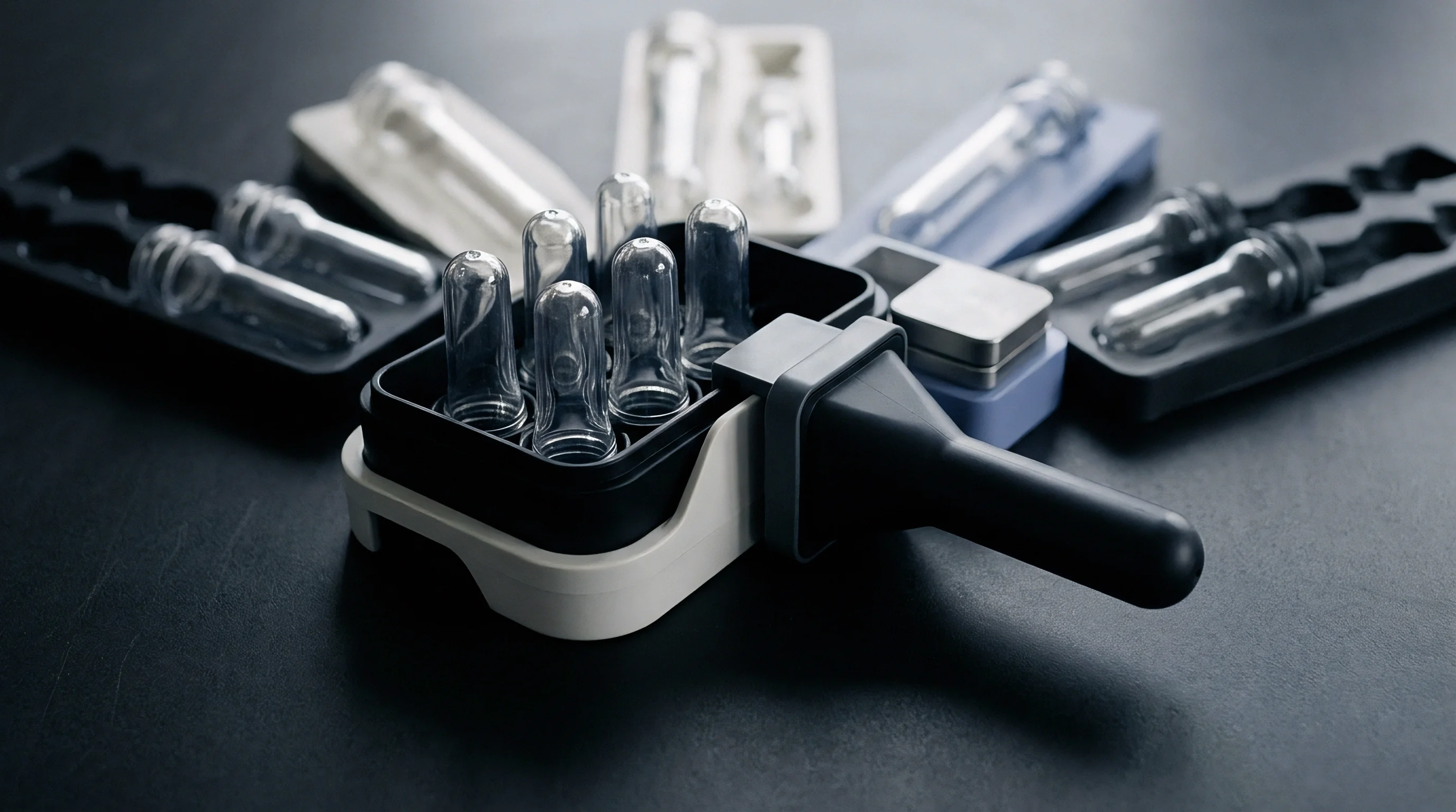
Phase Transition and Volumetric Shrinkage Dynamics
Volumetric contraction varies with temperature and pressure, as documented in PVT data. Amorphous polymers like polycarbonate shrink gradually as they cool through their glass transition. Semi-crystalline resins like polypropylene and glass-filled polyamides undergo a sharper volume drop during phase change as polymer chains organize into dense crystalline domains.
This abrupt contraction accelerates gap formation on textured tool surfaces.
Entrapped gas pockets restrict thermal conduction across the widening gap interface.
Gaps do not form uniformly across complex geometries. Flat regions with minimal draft separate early as the part shrinks toward its center of mass. Conversely, internal cores remain under pressure longer because the material shrinks onto the metal pins ~ maintaining elevated conductance on the core side while the outer cavity wall loses contact.
This asymmetrical cooling creates thermal gradients that induce residual stress and post-moulding distortion.

Air Clearance Kinetics during Pressure Bleed
Cavity pressure decays following gate freeze or hold pressure removal. As internal pressure approaches atmospheric levels, mechanical support for the thin outer skin disappears. At this stage, heat transfer modeling must transition from contact mechanics to conduction and radiation across an insulating air layer.
Conduction across an air gap varies inversely with gap width. The thermal conductivity of gas within the gap depends on temperature and volatile concentration, including moisture and organic compounds released by additives or thermal degradation. Because this clearance gap often equals or exceeds the depth of the texture pattern, macro-gap resistance becomes the dominant thermal barrier during late cooling.
Cavity pressure decays rapidly once hydraulic holding force ends.
Identifying the exact moment of detachment requires fast-response cavity pressure transducers combined with flush-mounted infrared temperature sensors in the tool. When contact stress drops to zero, the heat flux curve exhibits a distinct inflection point. Trial data showed a 1.8 second cooling delay on a VDI 33 textured core when post-gate-seal pressure fell below 4 MPa, confirming how much early thermal detachment hurts cycle time.
- Install flush-mounted piezo-electric pressure transducers directly behind the textured cavity region alongside fast-response surface thermocouples.
- Run a dynamic packing pressure scan, dropping hold pressure incrementally from maximum machine capacity to gate-seal thresholds in 5 MPa steps.
- Record transient heat flux profiles to pinpoint the exact moment the thermal decay slope breaks, signaling physical detachment.
- Calculate instantaneous thermal contact conductance by dividing measured heat flux by the difference between bulk polymer core temperature and steel surface temperature.
Chemical etching variations of six micrometres fall within standard commercial process allowances and cannot account for localized cooling delays.
Pressure
Packing force per unit area determines how effectively molten polymer penetrates micro-features on etched tool surfaces. Contact stress drives plastic and viscoelastic flow in the cooling skin, pressing it into micro-cavities, expanding actual contact area, and displacing air. Without adequate contact stress, an etched surface functions primarily as an insulating layer, extending cycle times and inducing thermal gradients across the part.
Relating cavity pressure to contact conductance requires adapting contact mechanics to account for polymer rheology during rapid cooling. At packing pressures below 10 MPa, the contact area ratio on a VDI 30 finish remains below 0.20, keeping thermal conductance under 800 W/m²K. Increasing cavity pressure to 60 MPa forces the semi-solid skin into micro-grooves, raising the contact area ratio above 0.65 and pushing conductance past 3200 W/m²K.

Mikic Yovanovich Contact Mechanics Adapted for Polymers
The Mikic-Yovanovich model for contact between rough surfaces provides a theoretical starting point. In its original form, contact conductance depends on surface roughness standard deviation, mean absolute profile slope, material hardness, contact pressure, and the harmonic mean thermal conductivity of the contacting materials.
Applying this model to injection moulding requires substituting static metal hardness with temperature-dependent flow stress and viscoelastic compliance. Polymer resistance to deformation drops near glass transition or melt temperatures, making the skin responsive to early packing pressure. As the polymer cools, yield stress rises rapidly, preventing further deformation into micro-features even if high pressure is maintained.
Thermal conduction remains low while interfacial contact stays limited.
Effective microhardness of the polymer skin is evaluated as a function of cooling rate, local temperature, and pressure duration. Rapid surface cooling locks in the contact area ratio achieved during high-pressure packing. Consequently, early application of packing pressure influences heat transfer far more effectively than pressure applied after skin formation.

Does Etch Depth Scale Contact Resistance Linearly?
Profile depth alone does not dictate thermal performance on textured tooling. Measurements across standard chemical finishes demonstrate that texture aspect ratio and spatial distribution exert greater influence than total profile height. Open textures with wide valleys permit polymer entry under moderate pressure, whereas narrow, high-aspect-ratio features trap air at their base.
Laser-textured surfaces featuring draft inside the micro-cavities show lower boundary resistance than acid-etched surfaces of equivalent profile height. Clear micro-draft angles reduce resistance as melt enters the pattern, yielding higher contact area ratios at lower injection pressures. Acid etching often leaves undercut micro-features that hinder complete melt penetration, trapping gas pockets that lower conductance across all pressure levels.
| Texture Standard | Profile Depth Rz (µm) | Conductance at 10 MPa (W/m²K) | Conductance at 35 MPa (W/m²K) | Conductance at 60 MPa (W/m²K) | Peak Area Ratio (Ar/Aa) |
|---|---|---|---|---|---|
| VDI 12 (Fine EDM) | 1.6 | 1450 | 3100 | 4200 | 0.82 |
| VDI 24 (Medium Acid Etch) | 6.3 | 850 | 2400 | 3500 | 0.68 |
| VDI 30 (Coarse Acid Etch) | 12.5 | 520 | 1650 | 2800 | 0.51 |
| VDI 36 (Heavy Textured) | 25.0 | 310 | 1100 | 2050 | 0.38 |
Interfacial resistance increases as profile depth grows larger.
Texture aspect ratios above 1.5 present significant barriers to melt penetration. In deep micro-pits, packing pressure must overcome both compressed gas pressure and the yield strength of the solidifying polymer. If cavity pressure drops before penetration occurs, contact conductance remains low throughout the cooling cycle.
- Melt Viscosity Indexing aligns flow properties with texture dimensions to set realistic packing pressure thresholds.
- Texture Depth Thresholding avoids overly deep etch patterns on wall sections far from the gate where pressure drops significantly.
- Packing Hydraulics Verification checks that machine limits actually deliver required contact stress at the end of fill.
Higher holding pressure drives molten polymer into etch valleys to convert gas-filled insulation zones into direct conductive pathways.
Matching pressure profiles to tool geometry enables predictable management of cooling performance. Pressure measurements from trial runs confirm whether packing forces reach remote textured regions early enough to establish solid contact before skin freezing.
Deeper texture depth requires higher packing pressure to prevent trapped insulating gas from extending cycle time.

Formulas
Determining interfacial conductance requires combining solid contact equations with gas gap terms across the cooling cycle. This formulation provides specific control over boundary conditions in thermal simulations. Total cavity conductance is modeled as solid contact conductance and gas gap conductance operating in parallel.
The mathematical representation follows the core equation:
h_c = h_s + h_g
where h_c is total thermal contact conductance in W/m²K, h_s is solid contact conductance, and h_g is gas gap conductance. The solid contact term depends on the effective thermal conductivity of the interface, feature spatial frequency, and actual contact area under load.

Mathematical Derivation of Combined Conductance
Solid contact conductance is calculated using a modified Cooper-Mikic-Yovanovich relationship adapted for polymer behavior:
h_s = 1.25 k_eff (m / sigma) (P_int / H_c)^0.95
Here, k_eff is the harmonic mean thermal conductivity of polymer melt and tool steel, defined as 2 k_p k_m / (k_p + k_m), where k_p is polymer thermal conductivity and k_m is steel conductivity. The parameter m represents the mean absolute profile slope of the etch, sigma is root-mean-square roughness height R_q, P_int is instantaneous cavity pressure at the wall, and H_c is effective microhardness of the solidifying polymer skin.
Gas gap conductance across micro-valleys is calculated using Knudsen conduction theory to account for small-scale gas layer dynamics:
h_g = k_g / (Y + beta M lambda_0 (T_g / T_0) (P_0 / P_g))
Here, k_g is gas thermal conductivity, Y is mean clearance gap height, beta is an accommodation coefficient for gas-wall energy exchange, M is a gas-specific parameter, lambda_0 is the mean free path of gas molecules at reference temperature T_0 and reference pressure P_0, T_g is gas temperature, and P_g is localized gas pressure inside micro-valleys.
Tool steel maintains elevated surface temperatures during early packing.
Mean gap height Y changes dynamically during moulding as polymer deforms into surface micro-features. Penetration depth h_pen under contact stress is calculated using viscoelastic squeeze flow dynamics:
h_pen = R_z (1 – exp(- (P_int t) / (eta_eff C_geo)))
where R_z is maximum texture profile height, t is effective packing time prior to skin freezing, eta_eff is zero-shear viscosity at boundary temperature, and C_geo is a dimensionless geometry factor characteristic of the etch pattern.

Worked Thermal Resistance Calculations across VDI Grades
A practical calculation illustrates these relationships. Consider glass-filled polyamide 66 (PA66-GF30) moulded against a VDI 27 acid etch finish. Baseline parameters include: polymer thermal conductivity k_p = 0.28 W/m·K, steel conductivity k_m = 29.0 W/m·K, surface roughness sigma = 4.5 micrometres, profile slope m = 0.18, polymer skin microhardness H_c = 42 MPa at skin transition, and peak cavity pressure P_int = 40 MPa.
Calculating harmonic mean thermal conductivity gives k_eff = 2 0.28 29.0 / (0.28 + 29.0) = 0.554 W/m·K. Substituting parameters into the solid contact equation yields:
h_s = 1.25 0.554 (0.18 / 4.5e-6) (40 / 42)^0.95 = 0.6925 40000 0.955 = 26460 W/m²K at direct microscopic contact points.
Under these conditions, the actual contact spot area ratio A_r / A_a equals 0.12. Adjusting pure spot conductance by this ratio produces net solid contact conductance h_s_net = 26460 0.12 = 3175 W/m²K.
Gas gap conductance across the remaining 88 percent non-contact area must also be evaluated. Trapped air at an estimated temperature of 450 K exhibits k_g = 0.037 W/m·K. Mean un-penetrated gap height Y equals 3.8 micrometres. Accounting for gas compression under 40 MPa internal pocket pressure yields h_g = 0.037 / (3.8e-6 + 0.2e-6) = 9250 W/m²K across non-contact zones.
Weighting by the non-contact area fraction gives net gas conductance h_g_net = 9250 0.88 = 8140 W/m²K under compressed conditions.
Combining both terms establishes peak cavity thermal contact conductance prior to pressure drop: h_c = 3175 + 8140 = 11315 W/m²K under compressed gas conditions. As micro-pockets vent or local gas pressure falls during cooling, h_g_net decreases to 450 W/m²K, leaving total contact conductance at h_c = 3175 + 450 = 3625 W/m²K during stable packing.
| Polymer Grade | Etch Finish | Applied Pressure (MPa) | Calculated Area Ratio (Ar/Aa) | Peak Conductance hc (W/m²K) | Detached Conductance (W/m²K) |
|---|---|---|---|---|---|
| PP Homopolymer | VDI 18 | 30 | 0.54 | 2850 | 320 |
| PP Homopolymer | VDI 30 | 30 | 0.28 | 1420 | 180 |
| PA66-GF30 | VDI 18 | 50 | 0.72 | 4100 | 410 |
| PA66-GF30 | VDI 30 | 50 | 0.41 | 2350 | 220 |
Volumetric contraction forms an insulating clearance gap along the interface.
Comparing calculated values with production press measurements shows that thermal contact conductance drops by over 80 percent once cavity pressure reaches zero. Simulations that assume constant conductance underestimate core heat retention and produce inaccurate cooling time estimates.
Specifications enforcing DIN 16742 Tolerance Group TG4 compel toolmakers to model cavity-wall thermal contact conductance explicitly rather than applying isotropic cooling assumptions.
Performing these calculations during tool engineering helps prevent post-trial tooling modifications. Engineering teams use these formulations to position cooling channels effectively, matching local cooling capacity to the thermal resistance of textured zones.
Standard tooling purchase specifications under ISO 20457 Clause 5.3 shift financial liability for warp defect re-tooling to the mould maker whenever calculated contact conductance values are omitted from cooling simulation signoffs.


Trial
Validating calculated heat transfer coefficients requires press-side testing using fast-response instrumentation. While analytical models provide baseline values, variations in steel machining, etching consistency, and resin lot viscosity necessitate empirical verification. Mould trials allow measurement of actual thermal boundary behavior to refine process settings before full production release.
Measuring thermal contact conductance accurately requires precise sensor placement near the cavity surface. Thermocouples positioned within 0.5 millimetres of the textured wall record rapid surface temperature shifts during initial fill. Combined with flush-mounted cavity pressure sensors, they supply synchronized data for inverse heat conduction analysis.

Instrumentation and Real Time Heat Flux Transducers
Capturing transient heat flux across the mould interface requires sensors with millisecond response capability. Standard probes exhibit response delays exceeding 500 milliseconds, missing initial surface temperature peaks. Erodible ribbon or thin-film coaxial thermocouples respond within 10 milliseconds, capturing rapid surface changes during injection.
Installing dual thermocouple pairs at precise depths perpendicular to the cavity wall enables direct calculation of heat flux. Applying Fourier’s one-dimensional heat conduction equation across the sensor spacing yields real-time heat flux through the tool steel. Dividing instantaneous heat flux by the temperature difference between the polymer core and steel surface isolates contact conductance across each phase of the moulding cycle.
Empirical measurements align closely with predicted conductance values.
Real-time temperature traces indicate rapid shifts in thermal behavior when processing parameters are modified. Lower melt temperatures reduce skin compliance, decreasing peak contact conductance during packing. Higher coolant flow rates reduce baseline steel temperature, accelerating skin freezing and narrowing the time window for pressure-driven texture penetration.

Inverse Heat Conduction Parameter Identification
Determining surface contact conductance from subsurface temperature measurements is an ill-posed inverse problem. Minor measurement noise in raw sensor data can generate significant errors in calculated heat flux without numerical regularization. Beck’s sequential estimation algorithm provides stable calculations for inverse thermal analysis in tooling applications.
The inverse solver aligns recorded steel temperature curves with predicted profiles from transient finite-element models. The algorithm adjusts surface conductance values iteratively until calculated temperatures match measured data within specified tolerances. This optimization method produces verified conductance curves corresponding to real press conditions.
- Sensor Calibration Dossier documents exact physical depth, thermal response constants, and signal amplifier scaling factors for cavity transducers.
- Cavity Pressure Profile Trace provides synchronized time-series data matching hydraulic packing force against surface heat flux changes.
- Thermal Imaging Logs record high-resolution surface temperature distributions immediately upon part ejection to verify cooling uniformity predictions.
Surface micro-cavities retain air until sufficient pressure forces penetration.
Multi-cavity trials frequently reveal variations in conductance between cavities. Minor differences in texture wear, etching depth, or balance in runner pressure can alter local thermal boundaries. Identifying these variations during initial qualification helps prevent dimensional drift during high-volume production runs.
Measured heat flux peaks within eighty milliseconds of cavity fill completion before decaying as surface skin freezes.
Engineering teams evaluate these records to refine heat transfer models and update design guidelines for upcoming tooling programs.
How laser-ablated micro-textures alter melt-solidification boundary kinetics compared to traditional chemical acid-etching under high-frequency pressure oscillations remains a subject of ongoing industry debate.


Yield
Production economics depend heavily on cycle time increases caused by thermal boundary resistance in textured cavity steel. Extended cooling requirements add measurable cost to high-volume manufacturing programs. Tooling specifications must evaluate aesthetic requirements alongside piece-price impacts resulting from longer cycle times.
A coarse acid etch finish such as VDI 33 can extend cooling times by 1.5 to 4.5 seconds compared to a polished SPI A2 cavity wall. On a nominal 15-second cycle, a 3-second delay reduces press output by 20 percent. Over a production run of 500,000 parts, this penalty represents an additional 41.6 press hours, increasing overall manufacturing costs.

Cycle Time Penalties and Financial Amortisation
Quantifying the economic impact of textured tooling requires converting thermal contact resistance into machine hourly rates. Operating costs scale with machine clamp tonnage, ranging from $45 per hour for a 100-ton press to $180 per hour for a 1200-ton hydraulic machine. A 3-second cooling extension on a 1200-ton press moulding textured interior panels adds $0.15 directly to the unit production cost.
Tooling amortization models must evaluate initial texturing expenditure relative to cumulative cycle penalties. Acid etching requires lower upfront capital than multi-axis laser texturing. However, laser texturing permits micro-drafted features that improve contact area at lower packing pressures, trimming 1.0 to 2.2 seconds from cooling requirements.
On high-volume programs, the cycle savings realized through laser texturing often offset the higher initial tooling investment.
Cooling delays directly extend the total injection moulding cycle.
Non-uniform cavity cooling also affects production yield. Inadequate contact conductance assumptions can lead to part ejection while internal cores remain above heat deflection temperatures. Incompletely cooled parts distort after ejection, exceeding DIN 16742 flatness tolerances and increasing scrap rates.

Tooling Capital Allocation and Quality Tolerances
Selecting texture grades requires matching surface finish requirements against specified part tolerance classes. Precision dimensions conforming to DIN 16742 Tolerance Group TG3 demand uniform thermal management. High thermal resistance from deep textures increases internal thermal gradients, making tight tolerances difficult to maintain without extending hold and cooling times.
Tooling specifications should clearly define allowable roughness parameters, required draft angles, and cooling line proximity for textured surfaces. Deep textures benefit from conformal cooling channels positioned near the cavity surface to counteract boundary resistance. Utilizing 3D-printed tool inserts with conformal channels helps manage surface temperatures behind heavily textured areas, mitigating cycle time penalties.
| Tool Surface Finish | Initial Tooling Delta ($) | Cooling Delta (sec) | Unit Cost Delta at 100k Units | Unit Cost Delta at 1M Units | Achievable DIN 16742 Grade |
|---|---|---|---|---|---|
| SPI A2 (Polished) | 0 (Baseline) | 0.0 | $0.00 | $0.00 | TG3 |
| VDI 18 (Fine Etch) | +$2,500 | +0.8 | +$0.041 | +$0.019 | TG3 |
| VDI 27 (Medium Etch) | +$3,800 | +2.1 | +$0.090 | +$0.053 | TG4 |
| VDI 36 (Heavy Etch) | +$5,200 | +3.9 | +$0.162 | +$0.102 | TG5 |
| Laser Engineered Texture | +$14,500 | +1.2 | +$0.175 | +$0.045 | TG3 |
Dimensional variation increases as thermal gradients widen across the part.
Reviewing tooling quotations requires verifying surface finish specifications against thermal performance criteria. Proposals offering low upfront costs may omit detailed cooling analysis for textured tool actions. Unanticipated cycle extensions identified during trial signoff impair projected margins and disrupt launch schedules.
Factoring textured thermal contact conductance into early estimates prevents unbudgeted cycle extensions and aligns part cost targets with actual machine rates before cutting steel.