Predicting Anisotropic Thermal Creep Modulus Decay in Injection Moulded Polyamide Structural Components
Anisotropic creep modulus decay in PA66-GF30 is governed by gate-induced fiber orientation, dropping transverse stiffness by 70% under thermal exposure.


Orientation
Injection moulded polyamide structural components reinforced with short glass fibres exhibit pronounced spatial variation in their creep response under sustained thermal and mechanical load. In a 30% short glass fibre reinforced polyamide 66 (PA66-GF30) bracket, the tensile creep modulus measured parallel to the polymer melt flow direction routinely reaches 8,500 MPa at 23 degrees Celsius dry-as-moulded, while the transverse direction yields approximately 4,800 MPa under identical loading conditions. Exposing that same component to 80 degrees Celsius under an applied stress of 30 MPa degrades these values non-linearly over time, dropping the longitudinal creep modulus below 3,200 MPa and the transverse modulus below 1,400 MPa within 1,000 hours.
Structural calculations that rely on isotropic modulus figures extracted from standard ISO 527 tensile bars predict a component deflection half as large as the real physical displacement observed on parts operating inside an engine bay or industrial pump housing.
Fiber alignment across the wall thickness generates this directional variance through a distinct skin-shell-core morphology. High shear stresses near the cold mould steel force the reinforcing glass fibers to align within 15 degrees of the flow vectors in the shell layers. Within the central core, extensional transverse flow forces those same fibers into an orientation perpendicular to the primary melt pathway.
When sustained mechanical stress operates at elevated temperatures, the unreinforced polyamide matrix relaxes via viscoelastic chain slippage, transferring load to the high-aspect-ratio glass fibers. Along the flow direction, fiber-matrix shear stress transfer restrains this strain accumulation. Transverse to the flow direction, the applied load acts directly across the polymer matrix without substantial reinforcement, producing accelerated creep strain rates and rapid apparent modulus collapse.
Under ISO 899-1 tensile creep testing at 80 degrees Celsius and 30 MPa sustained load, PA66-GF30 loses over sixty percent of its initial transverse stiffness within one thousand hours.
Predicting this directional stiffness loss over component lifetimes requires linking three discrete numerical domains: injection moulding flow kinematics, anisotropic homogenization mechanics, and viscoelastic-viscoplastic constitutive modeling. Process simulations yield the second-order orientation tensor across finite element shells or three-dimensional solid meshes. Micromechanical schemes, such as the Mori-Tanaka or double-inclusion formulations, transform these local orientation tensors into orthotropic elastic and viscoelastic stiffness properties.
Structural solvers then march through time under specified thermal and mechanical boundary conditions to compute creep strain accumulation, dynamic modulus degradation, and irreversible permanent set. Tool designers and procurement engineers who skip these directional mappings oversize components unnecessarily or face field warranty claims caused by unexpected fastener relaxation and mechanical interference.
The standard supply agreement frequently penalizes structural failure without providing a unified mathematical framework for anisotropic creep validation. Raw material datasheets present creep rupture and isochronous stress-strain curves derived exclusively from longitudinally oriented ISO 3167 Type A specimens tested in conditioned states. When a part fails due to creep-induced bending around a boss where fibers settled purely transverse to the load vector, suppliers invoke these standard coupon curves to argue that the material operated outside its design envelope.


Morphology
The internal arrangement of short glass fibers within an injection moulded cavity develops directly from the interaction between polymer melt rheology and transient thermal gradients. As molten polyamide enters a chilled mould tool through an edge or sub-gate, the material forms a advancing fountain flow front. Fluid elements decelerate near the centreline and stretch outward toward the cold tool walls, depositing a thin, rapidly frozen skin layer showing modest orientation.
Directly behind this advancing front, intense shear rates align the suspended fibres parallel to the local velocity vectors, constructing the shell layers. In typical structural wall thicknesses between 2.5 mm and 4.0 mm, these high-orientation shell layers occupy between 60 and 75 percent of the total cross-section.

Skin Shell and Core Layer Formation
Within the slower-cooling interior of the wall, extensional flow dominates over simple shear during the cavity filling and packing phases. Molten polymer flows outward toward expanding cavity boundaries, orienting the short glass fibers transverse to the primary filling direction. The resulting core layer exhibits an orientation tensor component along the flow direction that drops from roughly 0.80 in the shell down to 0.20 to 0.35 in the midplane.
Gate placement, fill speed, injection pressure, and melt viscosity dictate the relative thickness of each morphology zone.
A faster injection speed generates narrower core zones by confining high thermal gradients and concentrating shear forces closer to the tool walls. Decreasing injection speed allows the solidifying frozen layer to grow thick during filling, which shifts the shear zone inward and broadens the transverse core region. Post-filling packing pressure forces additional melt into the cooling cavity, inducing secondary flow lines that alter fibre angles in the transition zone between shell and core.
Variations in tool temperature alter the solidification rate of the outer layers, shifting the physical boundary where shear-induced orientation freezes into place.
| Morphology Zone | Wall Fraction (Percent) | Mean Fiber Angle to Flow (Degrees) | Orientation Tensor Component A11 | Initial Modulus at 23C Dry (MPa) |
|---|---|---|---|---|
| Frozen Skin | 3 to 6 | 35 to 45 | 0.48 to 0.55 | 6,100 to 6,800 |
| Outer Shell | 30 to 38 | 8 to 16 | 0.78 to 0.88 | 9,200 to 10,400 |
| Transition Zone | 12 to 18 | 25 to 35 | 0.52 to 0.62 | 6,400 to 7,200 |
| Central Core | 18 to 28 | 70 to 88 | 0.18 to 0.32 | 4,300 to 5,100 |
Orientation data within structural calculations relies on the second-order orientation tensor formulation. In this mathematical description, unity denotes complete parallel alignment along an axis, whereas a value of one-third represents a completely random, isotropic distribution in three dimensions. The primary flow-direction tensor component, designated as A11, serves as the direct scaling factor for directional mechanical properties.
The transverse planar component, designated as A22, captures reinforcement across the flow, while the through-thickness component, A33, remains consistently small due to physical planar confinement within thin-walled injection moulds.
Weld lines introduce severe structural disruptions into this layered morphology. When two opposing melt fronts converge head-on, the fountain flow pushes advancing polymer outward, forcing fibers to align entirely parallel to the weld plane and perpendicular to the primary tensile load vector. In cross-flow weld lines, where streams join along parallel courses, fibers tumble and fail to bridge the boundary zone cleanly.
The local value of A11 across a butt weld line plummets toward 0.10, cutting both the instantaneous tensile strength and long-term creep modulus by up to 65 percent compared to undisturbed shell properties.
The injection moulding setter adjusts holding pressure to eliminate sink marks, yet this packing phase drives melt displacement through the molten core while the shells remain frozen. This secondary displacement reorients core fibers into complex parabolic arches that deviate sharply from idealized midplane assumptions. When dynamic loading occurs at elevated temperatures, shear stress concentrations develop precisely at the interface between the high-modulus shell and the compliant core.
Delamination and accelerated micro-void formation at these internal boundaries trigger premature structural creep failure.
Plasticization
Polyamides contain repeating amide groups capable of forming strong intermolecular hydrogen bonds within amorphous and semi-crystalline regions. These hydrogen bonds restrict the mobility of polymer chains, establishing a dry glass transition temperature of approximately 65 to 75 degrees Celsius for PA66 and 50 to 60 degrees Celsius for PA6. When exposed to ambient humidity, atmospheric moisture diffuses into the amorphous domains, breaking interchain hydrogen bonds and replacing them with water-amide linkages.
This chemical swelling acts as an internal plasticizer, depressing the glass transition temperature into sub-ambient regimes.
Moisture absorption shifts the glass transition temperature of PA66 down to minus 5 degrees Celsius at saturation, while PA6 drops to minus 20 degrees Celsius. In typical operating conditions with 50 percent relative humidity at 23 degrees Celsius, PA66 reaches an equilibrium moisture content of approximately 2.5 to 2.8 percent by weight, which depresses its glass transition temperature to between 15 and 25 degrees Celsius. If an engineer applies structural creep loads at an operating temperature of 60 degrees Celsius, a dry moulding operates below its glass transition, while a moisture-conditioned moulding operates far above it.
This state shift triggers accelerated viscoelastic compliance and rapid apparent creep modulus decay.
A component conditioned to equilibrium moisture content at fifty percent relative humidity displays three times the primary creep rate of an identical dry-moulded part.
Moisture diffusion follows classic Fickian kinetics through thin-walled sections during early exposure phases, but deviates into non-Fickian dual-stage absorption during long thermal exposures. Thick wall sections take months to reach moisture equilibrium under ambient conditions, producing steep moisture gradients across the part thickness. The exterior surfaces become fully plasticized while the interior core remains dry and glassy.
This hygroscopic gradient induces non-uniform internal stress profiles, superimposing compressive residual stresses on the exterior shells and tensile residual stresses within the core.
| Base Polyamide System | Reinforcement by Weight | Moisture at 50% RH (Percent) | Dry Glass Transition (C) | Conditioned Glass Transition (C) |
|---|---|---|---|---|
| Polyamide 6 (PA6) | 30% Glass Fiber | 2.8 to 3.2 | 55 to 60 | -10 to -5 |
| Polyamide 66 (PA66) | 30% Glass Fiber | 2.2 to 2.6 | 70 to 75 | 18 to 24 |
| Polyamide 610 (PA610) | 30% Glass Fiber | 1.2 to 1.5 | 50 to 55 | 28 to 34 |
| Polyamide 12 (PA12) | 30% Glass Fiber | 0.6 to 0.8 | 40 to 45 | 32 to 38 |
| Polyphthalamide (PPA) | 30% Glass Fiber | 0.9 to 1.3 | 125 to 135 | 85 to 95 |
Thermal degradation compounds plasticization when operating environments exceed 100 degrees Celsius for sustained periods. Atmospheric oxygen attacks the tertiary carbons adjacent to the nitrogen atoms in the polyamide chain, generating hydroperoxides that decompose into free radicals. Chain scission reduces the molecular weight of the matrix, diminishing the entanglement density required to sustain mechanical loads over long durations.
Thermal aging also induces secondary crystallization, which shrinks the amorphous volume, embrittles the matrix, and increases interfacial stresses at the glass fiber boundaries.
Hydrolytic degradation occurs in pressurized aqueous environments or under cyclic condensing humidity at elevated temperatures. Water molecules actively cleave the amide backbone linkages, converting long polymer chains into shorter dicarboxylic acids and diamines. This reaction destroys the chemical integrity of the matrix irreversibly, accelerating long-term creep rupture mechanisms.
Components subjected to simultaneous mechanical load, high thermal exposure, and direct fluid contact show creep modulus decay curves that drop precipitously after an initial incubation period.
Suppliers frequently present ISO 1110 accelerated conditioning data to prove part suitability before shipment. That conditioning protocol exposes mouldings to 70 degrees Celsius and 62 percent relative humidity to reach equilibrium moisture rapidly without changing the crystalline structure. However, elevated temperatures encountered in industrial service accelerate physical aging, allowing polymer chains to relax toward lower thermodynamic enthalpy states.
This physical aging increases initial short-term modulus slightly, but reduces long-term creep ductility, predisposing highly stressed components to brittle micro-cracking along transverse core layers.

Formulation
Predicting anisotropic creep modulus decay requires establishing a multi-scale constitutive modeling framework that operates across several orders of spatial magnitude. The approach begins at the microscale, where the neat polyamide matrix and discrete short glass fibers interact, proceeds to the mesoscale representation of local orientation tensors, and terminates at the macroscale finite element component analysis. The effective creep compliance tensor of a representative volume element varies continuously throughout the component geometry based on local flow kinematics.

Micromechanical Homogenization
Homogenization schemes estimate composite stiffness by combining the isotropic properties of the reinforcing fibers with the time-dependent, viscoelastic properties of the surrounding polymer matrix. The Mori-Tanaka mean-field homogenization model provides a robust compromise between computational efficiency and predictive accuracy for two-phase composites with aligned or misaligned inclusions. This scheme considers an average stress state within the matrix phase, accounting for inclusion interactions by assuming each fiber behaves as an isolated inclusion embedded within an infinite pristine matrix subjected to the average matrix strain field.
The Eshelby tensor forms the foundation of this calculation, capturing the constraint imposed by the surrounding elastic medium on an ellipsoidal inclusion undergoing an unconstrained transformation strain. Short glass fibers are modeled as prolate spheroids with an aspect ratio defined by the mean fiber length divided by the mean fiber diameter, typically ranging between 20 and 35 in finished injection mouldings. Fiber attrition during screw plastification, melt conveyance through narrow runners, and passage through high-shear gates breaks long fibers down from their initial pellet length of 3.0 mm to an average distributed length between 180 and 320 micrometres.
Orientation averaging bridges the gap between perfectly aligned unidirectional composite formulations and the real, dispersed orientation observed in moulded parts. The local second-order orientation tensor, derived from mold-filling simulations using the Advani-Tucker formulation, requires closure approximations to reconstruct the full fourth-order orientation tensor. The orthotropic closure approximation and the invariant-based optimal closure approximation provide sufficient mathematical stability to map local stiffness matrices without generating non-physical, non-positive definite elasticity tensors.
Viscoelastic Constitutive Equations
The time-dependent compliance of the neat polyamide matrix is described mathematically using a generalized Maxwell model or a Prony series expansion of the relaxation modulus. The time-dependent linear viscoelastic shear modulus is expressed through the following formulation:
G(t) = G_inf + Sum(G_i exp(-t / tau_i))
In this equation, G_inf represents the fully relaxed long-term equilibrium shear modulus, G_i denotes the relaxation strength of the i-th Maxwell element, and tau_i defines the corresponding relaxation time spectrum. A matching Prony series formulation describes the time-dependent bulk modulus, capturing both deviatoric shear creep and volumetric deformation under multi-axial stress states.
Non-linear creep behavior emerges when the applied equivalent stress exceeds approximately 20 to 30 percent of the material yield strength at a given operating temperature. Under these conditions, linear viscoelasticity underpredicts real deformation rates. The Schapery single-integral non-linear viscoelastic representation incorporates stress-dependent functions into the compliance formulation:
J(t, sigma) = g_0(sigma) D_0 + g_1(sigma) Sum(D_i (1 – exp(-t / (a_sigma(sigma) lambda_i))))
The parameters g_0 and g_1 represent stress-dependent non-linear scale factors that amplify instantaneous and transient compliance respectively, while a_sigma acts as a stress-shift factor that accelerates the internal material clock, analogous to thermal time-temperature superposition. When localized stresses exceed the threshold for viscoplastic flow, an added Perzyna-type or Chaboche viscoplasticity model accounts for irreversible permanent strain accumulation alongside time-dependent viscoelastic recovery.

Time Temperature Superposition and Activation Energy
Thermal acceleration of creep relaxation obeys the time-temperature superposition principle across moderate temperature bands. For temperatures residing below the glass transition, the Arrhenius relationship describes the shift factor, a_T, governing the horizontal translation of creep compliance curves along the logarithmic time axis:
ln(a_T) = (E_a / R) (1 / T – 1 / T_ref)
Here, E_a defines the apparent activation energy for segmental chain motion, R represents the universal gas constant, and T_ref denotes the reference baseline temperature in Kelvin. For dry PA66, E_a typically ranges from 120 to 180 kJ/mol below the glass transition. When the operational temperature exceeds the glass transition temperature, the Williams-Landel-Ferry (WLF) equation provides superior mathematical accuracy:
log10(a_T) = -C_1 (T – T_ref) / (C_2 + (T – T_ref))
The empirical parameters C_1 and C_2 depend heavily on the moisture content of the polyamide matrix. Introducing absorbed water decreases both C_1 and C_2, compressing the relaxation timescale and shifting the creep curve horizontally toward shorter failure times.
A structured calculation sequence guides the predictive transfer from process simulation down to the final structural FEA mesh:
- Process Simulation Export maps flow velocity profiles, shear histories, and cooling rates across the cavity geometry using specialized injection moulding simulation software to extract node-specific second-order orientation tensors.
- Mesh Mapping and Alignment projects these tensor values from the fluid dynamics grid onto the structural mechanical finite element mesh, applying spatial interpolation algorithms that preserve through-thickness gradients.
- Fiber Length Distribution Integration adjusts inclusion aspect ratios per element based on calculated screw shear degradation and gate geometry losses rather than assuming uniform nominal fiber dimensions.
- Micromechanical Homogenization Execution evaluates the Mori-Tanaka equations at each Gauss point, synthesizing instantaneous anisotropic elastic stiffness matrices and directional Prony series parameters.
- Constitutive Stress Update evaluates time-temperature-moisture shift factors for current environmental boundary conditions, solving non-linear viscoelastic-viscoplastic strain increments at each loading step.
- Global Convergence Verification iterates through the structural solver time increments, updating element stiffness values and tracking local stress redistribution from relaxing core zones into high-stiffness shell zones.
Simulation packages execute this six-step sequence using proprietary material databases, but accuracy breaks down if the software relies on generic material cards. Toolmakers frequently discover that a generic PA66-GF30 material file assumes a static fiber aspect ratio of 30 and an isotropic core thickness of 10 percent, while actual moulded parts exhibit an aspect ratio of 18 and a core occupying 28 percent of the wall. This discrepancy leads the homogenization routine to overpredict the transverse creep modulus by up to 45 percent, resulting in non-conservative life estimates for critical load-bearing brackets.

Drift
Validating anisotropic creep decay requires moving past standardized ISO 899-1 uniaxial tensile creep tests performed exclusively on aligned flow specimens. A single tensile creep test conducted on an end-gated multi-purpose ISO 3167 specimen reflects only the shell-dominated longitudinal properties of that specific geometry. Structural components contain complex geometries that experience multi-axial, out-of-plane, and transverse stress fields.
Generating valid predictive data requires testing specimens milled directly from injection moulded plates at discrete orientations relative to the primary polymer melt flow vector.

Directional Test Matrix Execution
Coupons cut at 0 degrees, 45 degrees, and 90 degrees relative to the melt flow direction reveal the true orthotropic envelope of the material. A plaque measuring 150 mm by 105 mm by 2.0 mm, gated along its shortest edge, provides a controlled platform for extracting directional specimens. Testing these coupons under identical temperature and stress conditions reveals the dramatic divergence in creep compliance over prolonged exposure intervals.
| Loading Time (Hours) | 0-Degree Modulus (MPa) | 45-Degree Modulus (MPa) | 90-Degree Modulus (MPa) | Anisotropy Ratio (0 Deg / 90 Deg) |
|---|---|---|---|---|
| 0.1 (Instantaneous) | 6,200 | 4,100 | 3,050 | 2.03 |
| 1.0 | 5,450 | 3,450 | 2,450 | 2.22 |
| 10.0 | 4,700 | 2,850 | 1,950 | 2.41 |
| 100.0 | 3,950 | 2,250 | 1,500 | 2.63 |
| 500.0 | 3,350 | 1,850 | 1,200 | 2.79 |
| 1,000.0 | 3,050 | 1,650 | 1,050 | 2.90 |
| 5,000.0 | 2,500 | 1,300 | 820 | 3.05 |
The data demonstrates that anisotropic stiffness drift accelerates over time. While the instantaneous elastic modulus exhibits an anisotropy ratio of 2.03 between longitudinal and transverse directions, sustained thermal and mechanical loading drives this ratio up to 3.05 at 5,000 hours. The unreinforced transverse matrix relaxes rapidly through viscoelastic flow, while the longitudinal direction continues to derive mechanical reinforcement from the glass fibers bridging the stress path.
Calculations that apply a single time-decay reduction factor across an initial anisotropic stiffness matrix fail to capture this divergence, severely underestimating transverse deflection at extended service intervals.

Where Does the Empirical Fit Diverge?
Classical power-law formulations, such as the Findley creep equation, model primary and secondary creep strain with acceptable precision over short durations. The Findley equation expresses time-dependent strain as an instantaneous elastic component added to a transient power-law term:
epsilon(t) = epsilon_0 + m (t / t_0)^n
In this formulation, epsilon_0 represents the stress-dependent initial elastic strain, m defines the creep strain amplitude coefficient, t_0 is a unit reference time, and n represents the creep exponent, which typically ranges between 0.15 and 0.35 for glass-reinforced polyamides. When calibrated against 1,000-hour laboratory test data, the Findley model fits experimental points closely. However, extrapolating this power-law relationship beyond 5,000 hours introduces dangerous structural inaccuracies.
Physical aging, matrix micro-yielding, and interfacial fiber-matrix debonding eventually accelerate strain accumulation, initiating the tertiary creep stage that leads directly to rupture. Power-law formulations lack mathematical mechanisms to predict this upward inflection in strain rate. When applied to components operating above 80 degrees Celsius under moderate stress, Findley extrapolations often predict continuous stability where physical parts develop localized shear bands, micro-cavitation, and sudden structural collapse.
Multi-axial stress states further compromise standard predictive models. In pressurized fluid housings or torque-loaded mounting brackets, shear stresses act in combination with normal stresses. Under these biaxial states, the hydrostatic stress component accelerates free-volume expansion within the polyamide matrix, boosting local chain mobility and accelerating creep strain rates beyond values predicted by pure uniaxial equivalent stress formulations.
Incorporating a modified Drucker-Prager or Raghava equivalent stress criterion into the viscoelastic solver resolves this discrepancy, correcting the hydrostatic stress sensitivity of the relaxing matrix.
Dynamic mechanical thermal analysis (DMTA) frequency sweeps provide rapid characterization of the master relaxation curves, but converting dynamic loss and storage moduli into static creep compliance requires careful mathematical transformation. Tool designers frequently use the Ninomiya-Ferry numerical conversion method to extract creep compliance from storage and loss data. If the initial dynamic testing fails to capture physical aging kinetics occurring during long dwell periods, the converted compliance curve underpredicts total long-term creep strain by 20 to 35 percent.

Tooling
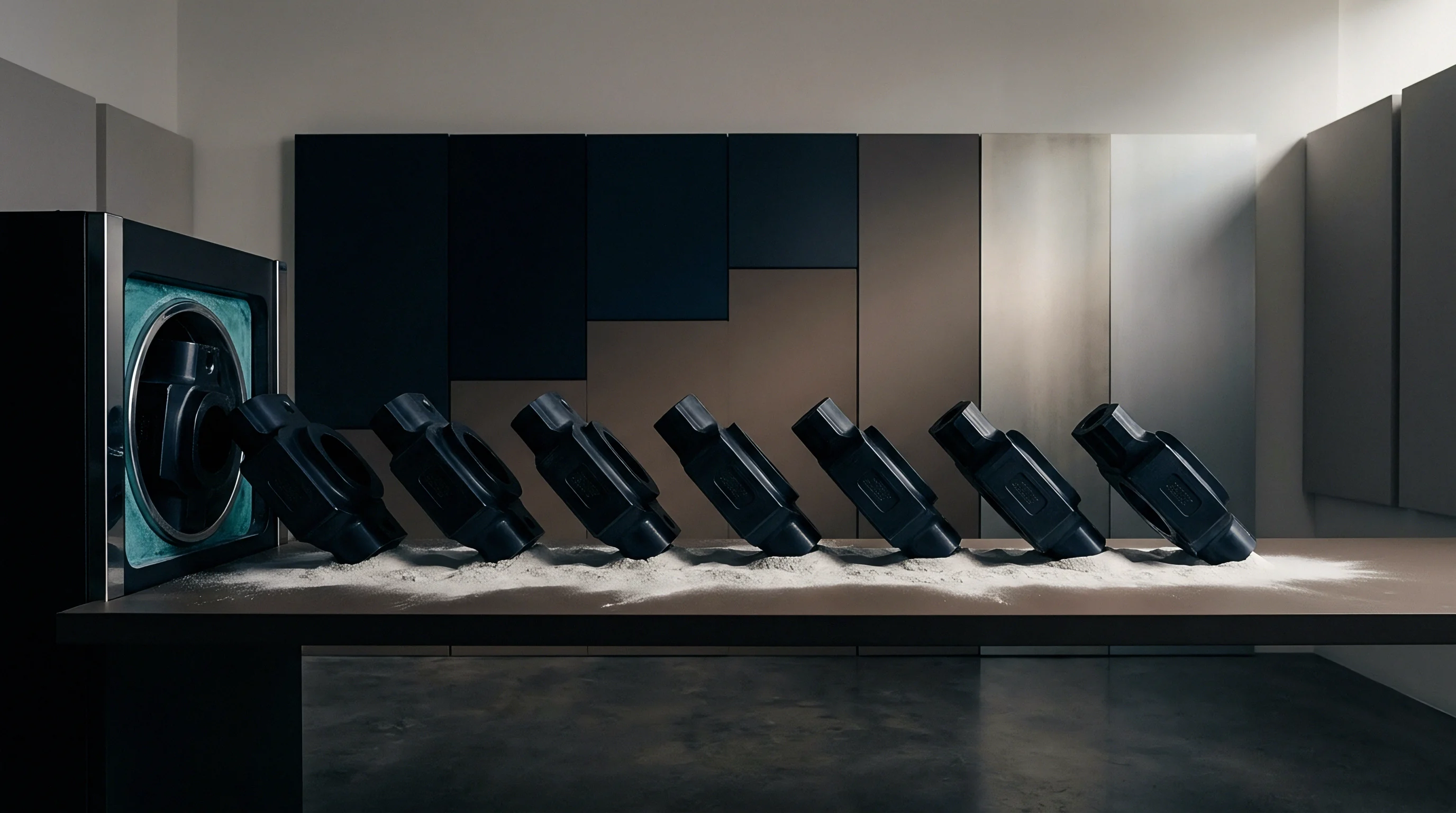
Controlling anisotropic thermal creep modulus decay in the physical component requires addressing the problem inside the toolroom before cutting tool steel. Gate location serves as the single most critical tooling decision dictating fiber orientation, morphology distribution, and directional creep performance. Placing an edge gate on the narrow end of a rectangular beam aligns fibers parallel to its longitudinal axis, optimizing flexural stiffness along the length.
Conversely, center gating that same beam produces radial flow vectors, creating an orientation pattern where fibers lie transverse to the primary bending moment along the beam edges, reducing flexural creep resistance by more than 50 percent.

Gate Architecture and Runner Influence
Submarine gates and pinpoint gates induce intense local shear rates during cavity filling. This extreme shear fragments glass fibers prematurely as they pass through the gate orifice, dropping the mean fiber length from 280 micrometres down to less than 150 micrometres in the immediate gate region. This local attrition impairs stress transfer efficiency, generating a localized zone prone to accelerated creep strain accumulation.
Fan gates and film gates distribute the melt across a wider frontage at lower shear rates, preserving fiber length and establishing uniform orientation profiles across critical structural sections.
Sequential valve gating in hot runner systems offers direct control over weld line placement and flow front orientation. Opening hot runner valve pins sequentially allows the melt front to pass an internal gate location before introducing fresh material, eliminating head-on butt weld lines entirely. Converting a structural bracket from simultaneous gating to sequential valve gating eliminates the weak transverse knit line, preventing catastrophic creep-induced weld fracture under prolonged thermal loading.
| Tool Design Parameter | Standard Practice Choice | Optimized Creep Mitigation Choice | Impact on Creep Modulus Decay |
|---|---|---|---|
| Gate Type | Pinpoint or Submarine Gate | Contoured Fan or Edge Gate | Preserves fiber aspect ratio, increasing long-term modulus by 15% to 20% |
| Gate Location | Parting line convenience | Aligned with principal tensile vectors | Maintains high A11 orientation parallel to stress, doubling creep life |
| Cooling Circuit Layout | Straight drilled waterlines | Conformal cooling channels | Eliminates asymmetric thermal gradients, stabilizing shell layer thickness |
| Cavitation Strategy | 8-cavity unbalanced layout | 4-cavity naturally balanced layout | Eliminates cavity-to-cavity filling variance, standardizing orientation fields |
| Core Pin Venting | Blind pin press-fit | Porous steel or active gas venting | Prevents air traps, preventing thermal degradation and micro-voids |
Tool cooling layouts dictate the symmetry and thickness of the high-orientation shell layers. Asymmetric cooling, where the cavity half runs at 90 degrees Celsius while the core half operates at 60 degrees Celsius to facilitate part ejection, generates uneven frozen layers. The hot tool surface allows slower cooling, producing a thinner shell layer with reduced orientation, while the cold tool surface freezes a thick, highly oriented shell.
This structural imbalance generates residual bending moments across the wall section, which cause progressive thermal warpage and uneven creep strain accumulation under service loads.
Conformal cooling channels manufactured via laser powder bed fusion in tool steels like 1.2709 allow cooling lines to track complex part contours smoothly. Maintaining a constant distance between cooling water and cavity surfaces eliminates hot spots in thick bosses and rib intersections. Eliminating these localized hot spots prevents the formation of thick, randomly oriented core zones, preserving higher average modulus values through the full part geometry.
Draft angles also influence packing efficiency and through-thickness morphology. Providing generous draft angles of 1.5 to 2.0 degrees allows the injection press to maintain effective holding pressure deep into the packing cycle without inducing part binding during ejection. Sustained packing pressure compresses the solidifying core, limiting volumetric shrinkage, suppressing internal micro-porosity, and increasing the mechanical density of the polymer matrix.
Dense, well-packed amorphous phases display superior resistance to viscoelastic chain slippage, reducing long-term creep modulus decay rates throughout the service envelope.

Verification
A structural creep prediction model provides genuine engineering value only when supported by a rigorous physical verification and receiving inspection protocol. Procurement specifications that rely entirely on certificate-of-analysis (CoA) data supplied by the resin compounder fail to protect the buyer. The resin compounder tests pristine ISO standard specimens moulded under ideal laboratory conditions, whereas the actual structural component contains complex flow paths, shear-induced fiber attrition, and morphology gradients dictated by the production tooling.

Digital Image Correlation Creep Testing
Verifying multi-axial anisotropic creep deformation on finished components requires full-field optical measurement techniques. Three-dimensional Digital Image Correlation (DIC) tracks surface strain development across complex injection moulded geometries during sustained thermal loading. Applying a stochastic speckle pattern to the part surface allows calibrated stereoscopic high-resolution cameras to measure three-dimensional displacement fields and calculate strain tensors across thousands of discrete surface facets over test periods exceeding 1,000 hours.
Conducting DIC creep tests within an environmental chamber held at 80 degrees Celsius and controlled relative humidity reveals localized strain concentrations invisible to standard displacement transducers. High-strain zones frequently emerge at the base of structural ribs, around internal core pins, and near weld line locations where simulation models predicted smooth stress distributions. Comparing the measured full-field strain tensor directly against the FEA creep simulation allows engineers to pinpoint inaccuracies in local orientation mapping, mischaracterized fiber length distributions, or inadequate non-linear viscoelastic constitutive formulations.
Destructive characterization of first-article mouldings confirms the microstructural assumptions embedded within the predictive simulation. Polishing cross-sections cut from critical structural locations allows optical reflection microscopy and automated image analysis to measure the second-order orientation tensor components through the wall thickness. Ellipse analysis of individual fiber cross-sections yields both the out-of-plane angle and the planar orientation angle, establishing whether the physical injection process matched the Advani-Tucker orientation predictions generated during the design phase.
Matrix ashing tests performed in accordance with ISO 3451-4 verify reinforcement content across different zones of the component. A component drawing that calls for 30 percent glass reinforcement by weight may display local variations between 26 percent and 33 percent due to fiber-matrix segregation occurring during high-speed cavity filling through thin web sections. Burning off the polyamide matrix at 600 degrees Celsius in a muffle furnace isolates the glass fibers, allowing subsequent length measurement using automated optical image analyzers to confirm that average fiber length has not dropped below the critical threshold required for effective shear load transfer.
Establishing enforceable receiving criteria requires incorporating standardized mechanical benchmarks into purchase agreements:
- X-ray Computed Tomography Scans confirm through-thickness fiber orientation tensor distributions and internal void fractions across structural zones, establishing a non-destructive volumetric baseline prior to production sign-off.
- Dynamic Mechanical Thermal Analysis Traces measure storage modulus and glass transition temperature shifts on coupons machined directly from moulded parts, verifying matrix polymerization and stabilizer additive effectiveness.
- High-Temperature Isochronous Creep Screening applies sustained mechanical loads to production components at 80 degrees Celsius for 100 hours, rejecting manufacturing lots that exceed specified maximum deflection limits.
- Residual Stress Chemical Immersion Checks expose parts to zinc chloride or lithium halide solutions to reveal localized frozen-in moulding stresses that accelerate environmental stress cracking and premature creep rupture.
When buyers audit component qualification dossiers, the most common deficiency is the absence of environmental conditioning records. Moulded polyamide brackets tested for creep compliance directly out of the injection mould display superior short-term stiffness that collapses once the part absorbs ambient moisture in warehouse storage or during sea transit. Quality agreements must specify that all qualification creep verification occurs on specimens conditioned to equilibrium moisture content in accordance with ISO 1110, establishing performance baselines that reflect true operating conditions rather than transient dry-as-moulded states.
DIN 16742 sets tolerance groups for injection moulded plastic components, establishing achievable dimensional limits based on material shrinkage characteristics and tooling precision. However, DIN 16742 addresses only initial dimensions post-moulding. Tool drawings for polyamide structural components carrying sustained loads must include creep allowances, sizing critical features to accommodate predicted anisotropic deflection over the design life.
Failing to link tolerance definitions directly to time-dependent anisotropic modulus decay guarantees that components will drift out of geometric compliance well before reaching their planned operational lifespan.
Standard supply contracts regularly omit explicit liability for long-term creep failure, treating progressive modulus decay as ordinary component wear. Moulders point to compliant first-article dimensional reports and raw material compounder certificates to defend parts that deform excessively after six months of thermal exposure. Buyers who protect their investments draft procurement terms that define maximum allowable deflection under specified load, temperature, and humidity conditions over 2,000 hours of continuous service, requiring the moulder to demonstrate that tooling geometry, gate location, and process parameters maintain structural compliance over time.