Predicting Dynamic Thermo Mechanical Deflection and Parting Line Wear Limits across Multi Plate Assemblies
Predicting parting line wear and deflection requires balancing support pillar layouts, steel hardness, and thermal expansion gaps against resin flash limits.


Stack
Injection pressures reaching 180 to 220 MPa inside cavity impressions act as internal hydraulic jacks, bending backing plates, support platens, and cavity retainers across multi-plate tool assemblies. Structural deflection across plate stacks creates non-uniform parting line separation, leading directly to plastic flash, crushed vent channels, and severe localized steel stress. Calculating plate flexure requires viewing the multi-plate assembly not as a solid monolithic block, but as a series of stacked elastic beams resting on discrete support pillars, ejector housing rails, and machine platen faces.
When peak cavity pressure hits during the filling and packing phases, the center of the cavity plate deflects outward away from the machine platen while the outer edges remain constrained by tie-bar clamp force. Elastic deformation in mold plates scales cubically with unsupported span length and inversely with the cube of plate thickness. A 58 mm cavity plate supported only by outer riser blocks experiences central deflection six times greater than an 88 mm plate under identical clamping and cavity loading conditions.
Bending deflection across central cavity spans exceeding 0.025 mm triggers localized polymer flash in low-viscosity resins like unfilled polyamide 66 at standard melt temperatures.
Plate flexure introduces uneven contact pressure distribution across the shut-off surfaces. Central clamping pressure drops as the core and cavity plates bow away from each other, shifting the mechanical clamp tonnage entirely to the outer perimeter of the parting line. This uneven tonnage distribution accelerates steel fatigue, causing micro-fracturing along sharp shut-off corners and permanent hobbing of the mold faces.
Structural plate deformation manifests in specific tooling and part failure patterns across high-pressure production runs:
- Perimeter parting line hobbing occurs when excessive clamp force concentrates on the outer plate shut-offs because central cavity pressure pushes the inner plate region backward into unsupported clearance gaps.
- Uneven wall thickness distribution arises when core plates deflect asymmetrical under unbalanced runner layouts or single-sided side-gate positions, moving core pins out of geometric concentricity.
- Interlock galling and seizure happens when side-action slide retainers and tapered guide blocks experience lateral displacement secondary to main plate flexure during maximum packing pressure pulses.
- Co-planar plate separation occurs in three-plate and runnerless assemblies where intermediate stripper plates bend away from cavity retainers, creating internal melt leakage behind hot runner nozzles.
Backing plate thickness sizing depends directly on support pillar arrangement and machine platen stiffness. Incorporating pre-loaded support pillars behind cavity impressions reduces central deflection by transforming broad bending spans into short, continuous-beam clear spans. Support pillar preload ranges between 0.03 mm and 0.05 mm taller than surrounding riser rails to guarantee immediate load resistance under full hydraulic clamp compression.
| Steel Grade | Hardness (HRC) | Flexural Modulus (GPa) | Plate Thickness (mm) | Unsupported Span (mm) | Max Calculated Deflection (mm) |
|---|---|---|---|---|---|
| 1.2311 (P20) | 30-32 | 205 | 46 | 120 | 0.042 |
| 1.2738 (P20+Ni) | 32-35 | 205 | 56 | 120 | 0.023 |
| 1.2343 (H13) | 48-52 | 215 | 56 | 120 | 0.021 |
| 1.2083 (420SS) | 50-54 | 200 | 66 | 120 | 0.013 |
| 1.2344 (H13 ESR) | 52-54 | 215 | 76 | 120 | 0.008 |
Ignoring plate bending dynamics during initial tool layout guarantees parting line flash, ruined shut-offs, and premature mold re-machining costs before reaching fifty thousand production cycles.

Gradient
Temperature variation across multi-plate mold structures induces differential thermal expansion that directly alters tool clearances, parting line alignment, and shut-off preloads. A hot runner manifold plate operating at 280 degrees Celsius expands substantially against a cavity plate cooled to 40 degrees Celsius, creating continuous lateral micro-motion at the interface between plates. When plates held at different thermal states are bolted together, thermal stress builds until friction gives way to microscopic slip events.
Thermal expansion follows the linear coefficient of thermal expansion for the specified steel chemistry. High-alloy hot-work steel expands roughly 12 to 13 micrometers per meter for every degree Celsius rise in temperature. Across an 800 mm manifold plate heated from ambient 20 degrees Celsius to an operating process temperature of 260 degrees Celsius, total radial growth reaches 2.49 mm from the center location pin out to the corner drop nozzles.
- Melt manifold temperature reaches setpoint while mold base remains ambient, causing hot runner nozzles to shear laterally against cold cavity gate bushings.
- Core plate coolant valves open, dropping core temperature to 25 degrees Celsius while cavity plate stays at 60 degrees Celsius under rapid molding cycles, expanding cavity dimensions relative to core locks.
- Guide pins experience asymmetric thermal loads, driving pin OD surfaces into forced interference contact against guide bushing walls during mold closing movements.
- Parting line contact pressure shifts dynamically throughout steady-state operation as local thermal equilibrium changes across cavity inserts and outer mold frames.
Hot runner nozzle centers shift relative to cavity gate centers during heat-up. Precise dowel positioning at the mold center point forces thermal expansion outward in a predictable, radial pattern. Dowel pins placed at peripheral plate locations restrict expansion, generating internal thermal stresses exceeding the yield strength of pre-hardened mold steel and distorting nozzle alignment axes.
According to ISO 20457, tool structural calculations assign a nominal thermal expansion tolerance band of plus or minus 0.015 mm per 100 mm of span length across active cavity plate surfaces.
Platen heat transfer introduces secondary thermal gradients along the thickness axis of backing plates. Water channels located too close to plate interfaces draw heat unevenly, creating bow-shaped thermal warping across large plate spans. Placing insulation boards between machine platens and mold clamping plates preserves thermal isolation, stabilizing internal plate temperature fields and locking parting line shut-off alignment within target tolerances.
Tooling vendors often claim that guide pin galling stems from lack of operator grease rather than thermal growth miscalculations across hot runner stripper plates. This excuse ignores basic thermal expansion physics, masking improper expansion clearances around guide bushings and thermal isolation gaps.

Abrasion
Repetitive cyclic contact combined with microscopic lateral sliding at shut-off surfaces initiates fretting corrosion, abrasive wear, and adhesive material transfer across mold parting lines. As the press locks toggle or hydraulic clamp pressure home, land surfaces press together under compressive stresses ranging from 100 to 300 MPa. Small lateral shifts caused by dynamic frame deflection or thermal movement force these compressed faces to rub together, stripping protective oxide films and creating metallic micro-debris.
Fretting wear generates fine oxidized steel particles that lodge between mating mold faces. These loose oxidized iron particles act as hard abrasive grains, gouging microscopic trenches into the polished shut-off lands during subsequent mold closing cycles. Over tens of thousands of clamp cycles, localized land height decreases by 0.010 mm to 0.035 mm, eroding the critical parting line shut-off seal.
Interlock surfaces experience severe adhesive wear when mating steel grades share identical hardness and chemical compositions. Uncoated pre-hardened P20 sliding against pre-hardened P20 under high contact pressure creates microscopic cold welds. As the mold opens, these welds snap, tearing metallic fragments out of both surfaces and leaving ragged, pitted surfaces that rapidly destroy shut-off integrity.
| Core / Cavity Material | Counter-Face / Lock Material | Surface Treatment | Friction Coefficient | Wear Rate (10^-6 mm³/N·m) | Galling Threshold (MPa) |
|---|---|---|---|---|---|
| 1.2311 (30 HRC) | 1.2311 (30 HRC) | None (Bare Steel) | 0.75 | 12.4 | 45 |
| 1.2343 (50 HRC) | 1.2343 (50 HRC) | Gas Nitrided (1000 HV) | 0.35 | 1.8 | 180 |
| 1.2344 (52 HRC) | Ampco 18 Bronze | None | 0.22 | 2.1 | 140 |
| 1.2083 (52 HRC) | 1.2083 (52 HRC) | Physical Vapor DLC | 0.12 | 0.3 | 310 |
| 1.2379 (58 HRC) | 1.2379 (58 HRC) | PVD TiAlN Coating | 0.18 | 0.5 | 280 |
Parting line degradation alters part wall dimensions along shut-off borders and creates flash flash boundaries that breach product specification limits. Downstream assembly lines reject components carrying flash tails as small as 0.03 mm, which interfere with automated ultrasonic welding fixtures and secondary seal seats.
Standard tooling supply contracts mandate that parting line wear exceeding 0.015 mm depth within the first 500,000 cycles constitutes a primary tool design defect, obligating the toolmaker to replace damaged inserts and re-engineer shut-off land bearing areas at their sole expense.


Predictor
Mathematical modeling of parting line wear limits relies on combining structural finite element deflection matrices with Archard’s wear equations. Calculating wear volume requires integrating contact pressure distributions across the shut-off surface area over the total sliding distance generated per clamp cycle. Dynamic simulation couples transient thermal expansion profiles with mechanical cavity pressure pulses to output predicted parting line life expectancies.
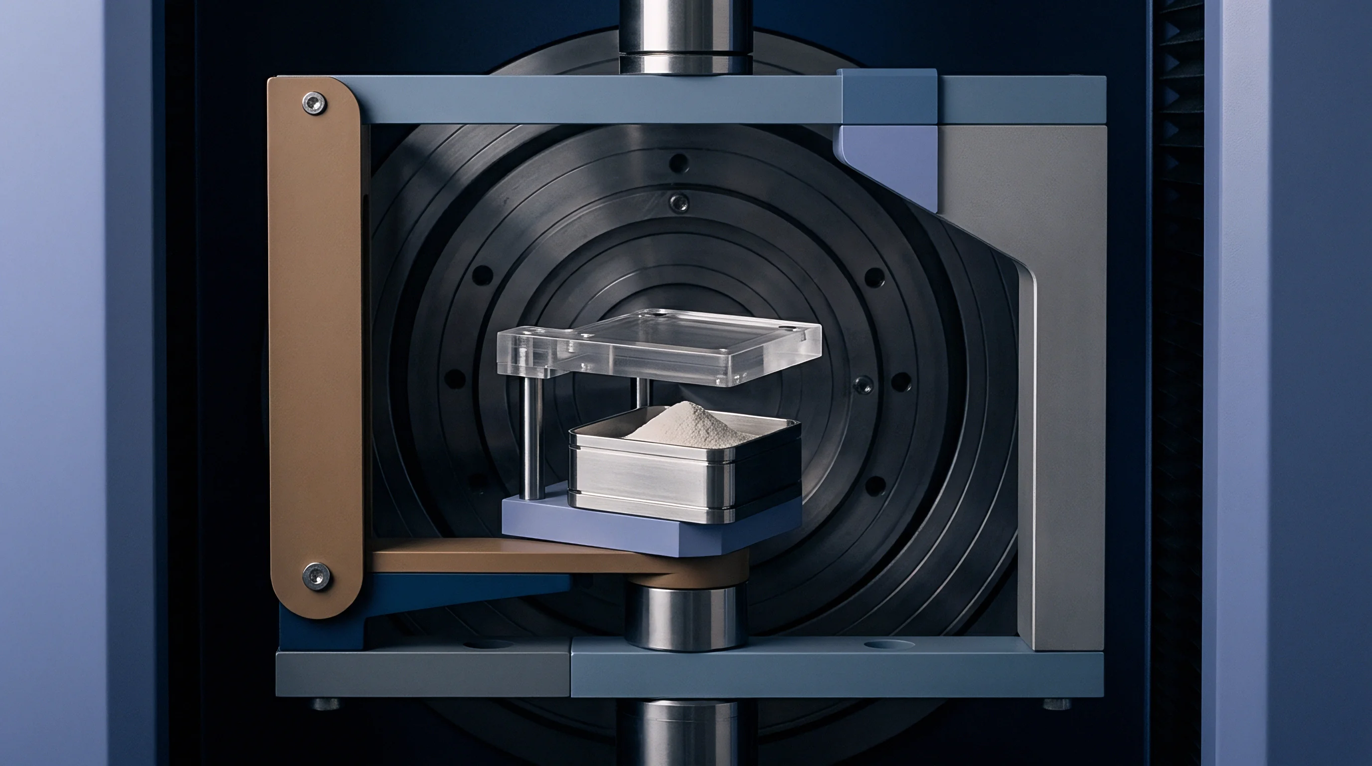
Is Local Parting Line Wear Predictable Using FEA?
Finite element analysis accurately predicts macro-level plate deflections and global thermal expansion shifts across multi-plate assemblies. Precise localized wear prediction remains difficult because real-world microscopic surface roughness, lubrication degradation, and airborne shop contaminants alter local friction coefficients during extended production runs.
Archard’s classic wear calculation defines total worn volume as proportional to normal contact force multiplied by sliding distance and divided by the surface hardness of the softer mating material. Dimensional wear depth derives directly from multiplying localized contact pressure by the specific wear coefficient and microscopic slip distance occurring per injection cycle.
To evaluate parting line flash risks, compare calculated tool deflection clearance gaps against the critical viscosity-dependent flashing threshold of specific polymer resins. Melt viscosity drops rapidly at elevated shear rates during injection filling, enabling liquid polymer to enter microscopic parted gaps under high hydrostatic core pressure.
| Polymer Resin Grade | Melt Temp (°C) | Mold Temp (°C) | Viscosity at 1000 1/s (Pa·s) | Flashing Gap Threshold (mm) |
|---|---|---|---|---|
| PA66 (Unfilled) | 280 | 80 | 85 | 0.010 |
| POM (Copolymer) | 205 | 90 | 140 | 0.015 |
| PP (Homopolymer) | 230 | 40 | 110 | 0.018 |
| ABS (Standard Grade) | 240 | 60 | 220 | 0.030 |
| PC (Unfilled) | 300 | 90 | 310 | 0.038 |
| PBT (30% Glass Filled) | 260 | 80 | 185 | 0.022 |
Worked predictive calculations reveal how minor changes in plate support layout dramatically alter tool life. Take a 64-cavity connector mold running unfilled polyamide 66 with a 0.010 mm maximum allowable flash gap limit. Finite element modeling under 200 MPa injection pressure shows central plate flexure producing a 0.018 mm opening gap along the inner cavity shut-offs, exceeding resin flow boundaries by 0.008 mm.
Adding four 40 mm diameter hardened support pillars directly behind the central cavity core blocks reduces total flexure to 0.006 mm, keeping parting line separation safely below the critical 0.010 mm flashing limit.
Engineers calculate total shut-off clearance by summing initial toolroom machining tolerances, thermal expansion differentials, dynamic plate deflections, and projected abrasive wear depth over time. The combined stack-up formula models the operational state:
Total Gap = Tooling Machining Tolerance + Plate Deflection + Differential Thermal Expansion + (Cycle Count × Wear Depth per Cycle)
Setting maximum allowable continuous wear limits requires identifying when total gap accumulation equals the resin flash threshold under peak filling pressures.
Unresolved questions persist regarding how high-frequency micro-vibrations originating from servo-electric clamp toggle mechanisms accelerate fretting oxidation rates at parting line contact points.

Steel
Selecting appropriate steel chemistries, heat treatments, and surface engineering treatments provides the structural defense against dynamic parting line wear and thermo-mechanical bending. High-stress multi-plate assemblies require tough core-backing plates combined with exceptionally hard, fatigue-resistant cavity inserts and wear pads. Proper material pairing balances mechanical yield strength against wear resistance while preventing micro-fretting galling modes.
Powder metallurgy tool steels offer superior carbide dispersion compared to conventional ingot-cast alloys, dramatically improving edge toughness and micro-chipping resistance along delicate parting line shut-offs. Vacuum heat treatment followed by multiple tempering cycles eliminates residual tensile stresses, ensuring dimensional stability across thermal processing cycles.
Selecting surface coatings and steel combinations requires evaluating distinct operational roles across the multi-plate assembly:
- Hardened wear plates manufactured from oil-hardening O1 steel or premium aluminum bronze alloys absorb sliding friction beneath side-action slides, protecting main frame plates from direct gouging wear.
- Physical vapor deposition coatings such as Diamond-Like Carbon or Titanium Aluminum Nitride apply ultra-hard, low-friction micro-layers over hardened tool steel inserts, dropping sliding friction coefficients below 0.15.
- Deep case nitriding generates a hard diffusion layer up to 0.3 mm deep with surface hardness exceeding 65 HRC, protecting cavity shut-off lands against high-impact clamping stress and abrasive resin wear.
- Guided ejection interlocks incorporating self-lubricating graphite inserts eliminate oil contamination risks in cleanroom molding environments while maintaining precise side-to-side alignment across parting surfaces.
Surface treatments must preserve underlying base metal geometry without introducing thermal distortion. Low-temperature PVD processing conducted below 500 degrees Celsius prevents loss of base steel temper hardness, whereas conventional chemical vapor deposition carried out at 1000 degrees Celsius causes catastrophic dimensional warping across finished mold plates.
DIN 16742 mandates structural tool steel design allowances that bound parting line shut-off deformation within Class TG3 tolerance standards for precision engineering moldings.
Harder steels placed at shut-off lands prevent localized hobbing, while softer sacrificial wear surfaces direct sliding abrasion into easily replaceable component plates.

Closure
Preventing premature parting line failure requires integrating deflection limits, thermal expansion calculations, and tribological steel selection into the initial tooling design phase. Dynamic thermo-mechanical modeling validates backing plate thickness, support pillar positions, and interlock clearances long before raw forging blocks arrive at the toolroom machining center. Managing parting line life extends beyond specifying high clamping force; it demands balancing structural stiffness against continuous thermal micro-motion across every plate interface within the assembly.
Tool qualification protocols demand running continuous twenty-four-hour thermal stability trials at maximum production cadence before final buyer sign-off. Optical profilometry scans conducted across T1 sample shut-off lands verify whether calculated deflection gaps remain inside target viscosity flash thresholds under production molding conditions. Documenting base wear patterns during initial lot sampling establishes baseline reference profiles for tracking long-term mold health.
Establishing clear maintenance rebuild thresholds protects valuable cavity tooling investments. Production facilities schedule parting line remachining when shut-off land wear reaches 60 percent of the critical polymer flash gap thickness. Refurbishing worn shut-off faces via precision laser welding and micro-milling restores initial shut-off planes, preserving tool longevity and preventing catastrophic parting line damage across multi-million cycle production runs.