Optical and Pressure Foil Standardisation for Automated Inspection of High Cavitation Shutoff Lands
Optical scanning and calibrated pressure foil convert shutoff land inspection into digital metrics, securing flash-free runs on high-cavitation tools.


Plane
Shutoff lands on a 96-cavity medical pipette tool maintain sealing across parting surfaces narrower than 0.8 mm. When a press clamps 200 tonnes across hardened 1.2343 ESR tool steel, contact pressure distributes unevenly across the matrix. A difference of 3 µm in local land height changes contact pressure by 45 MPa, moving steel from safe elastic seal into yielding or allowing polymer blow-by.
Parting faces rely on planar uniformity across every pocket to halt melt fronts driven at 120 MPa injection pressures.
Flash forms when local parting face separation exceeds the critical sealing gap of the resin. For an unfilled polypropylene with a melt flow rate of 25 g/10 min under ISO 1133 test conditions, that gap measures 0.012 mm. Polyethylene with lower melt viscosity flashes at 0.008 mm.
Toolmakers historically diagnosed parting contact by wiping Prussian blue paste over the cores, closing the clamp, and reading the transferred pigment by eye. The paste spreads in fluid films between 0.005 mm and 0.020 mm thick, obscuring micro-gaps and defying digital capture.
Parting surfaces under 200 tonnes of clamp force deform locally according to the stiffness of the backing plate.
Automated inspection replaces paste transfer with standardized sensory mediums. These mediums pair physical micro-encapsulated pigment sheets with high-resolution digital image capture. Calibrated tactile foils compress under mechanical load, releasing colour-forming chemistry at calibrated stress thresholds.
The resulting optical density map delivers dimensional data to vision inspection stations running telecentric optics, eliminating visual estimation from mold sign-off.

Parting Face Mechanics under Clamping Loads
Platens bend under machine tie-bar loads. Center cavities compress early while corner cavities lift, yielding non-uniform mechanical preloads across high-cavitation matrices. Tool designers cut landing pads 0.015 mm to 0.030 mm proud of core inserts to absorb machine force and protect delicate edge geometries.
These raised perimeter lands limit the crush transferred to cavity perimeters. The machine setter verifies that shutoff lands receive enough compressive stress to seal against the melt pressure without exceeding the compressive yield strength of the steel, typically 1400 MPa for tool steels tempered to 52 HRC.
| Steel Grade | Hardness (HRC) | Yield Stress (MPa) | Target Sealing Range (MPa) | Crush Limit (MPa) |
|---|---|---|---|---|
| 1.2343 (AISI H11) ESR | 50 to 52 | 1420 | 60 to 90 | 350 |
| 1.2083 (AISI 420) ESR | 52 to 54 | 1500 | 70 to 105 | 400 |
| 1.2767 (AISI 6F7) | 54 to 56 | 1650 | 80 to 120 | 450 |
| Ampcoloy 940 (CuNi2Si) | 28 to 30 | 580 | 25 to 45 | 140 |
Differential thermal expansion compounds mechanical deflection during production. A core half running hot oil at 90 degrees Celsius expands more than a cavity side cooled with chilled water at 15 degrees Celsius. The dimensional mismatch shifts interlocking tapers and rubs shutoff faces.
Optical assessment confirms whether tool room fitting accounts for thermal growth or if shutoffs bind during cycling.
The supplier argues that hand-stoning shutoff lands until blue transfer appears solid delivers sufficient seal integrity for the production run.

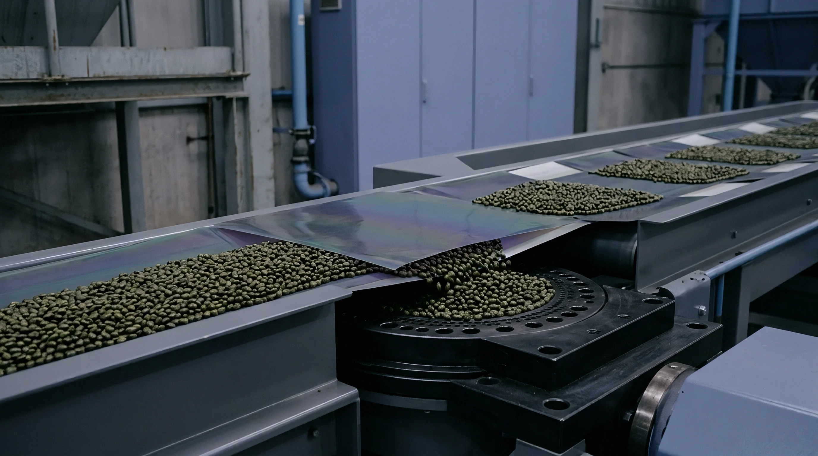
Crush
Tactile pressure foil houses micro-encapsulated colour-forming chemistry on a polyester backing. Pressure bursts the synthetic micro-capsules, discharging a leuco dye that reacts with a developer layer to generate a magenta hue. Mono-sheet variants carry the developer and micro-capsules on a single 100 µm film.
Two-sheet formats separate the donor micro-capsules onto a 40 µm film and the developer onto a matching 50 µm receiver film, creating a 90 µm sandwich. The density of the colour matches the peak compressive stress applied across the parting faces.

Chemical Film Formats and Contact Mechanics
Film compression mechanics require attention to physical thickness. Inserting a 0.090 mm foil between shutoff lands introduces artificial spacing. Toolmakers relieve cavity perimeters to ensure contact concentrates exclusively on primary lands.
Clamping a tool over a uniform sheet without cavity relief deforms the foil into vacant mold pockets, tearing the polyester carrier and smearing the dye. Automated evaluation uses precut foil strips cut by digital flatbed knife tables to match parting lines.
- Low pressure foils cover contact stresses from 2.5 MPa to 10.0 MPa to verify initial shutoff contact before full clamp tonnage engages.
- Medium pressure sheets resolve contact between 10.0 MPa and 50.0 MPa, isolating local zones starved of machine tonnage across the inner matrix.
- High pressure materials register values between 50.0 MPa and 130.0 MPa, highlighting destructive localized preloads capable of fatiguing mold steel.
- Ultra high films record compressive loads from 130.0 MPa to 300.0 MPa to audit landing pad crush blocks positioned on main mold bases.
Foil tests demand strict exposure controls. Technicians hold clamp pressure for precisely 120 seconds. Capsule rupture exhibits viscoelastic dependency, producing deeper colour density under prolonged dwell times.
Tool temperature also alters micro-capsule wall compliance. Running tests at 80 degrees Celsius softens the capsule shells, shifting the calibration curve by 18 percent compared to ambient shop tests at 20 degrees Celsius.
Holding clamp tonnage beyond two minutes skews dye density values above actual parting line loads.
Dwell periods must be standardized across every test cycle. Uncontrolled clamp release introduces shear marks, which crush remaining capsules and generate reading artifacts. Clamping speed must stay below 5 mm/s during the final 2 mm of stroke to prevent dynamic impulse loads from distorting the reading.
A buyer writes foil grade selection, dwell duration, and press temperature directly into the tooling validation protocol to secure repeatable land audits.
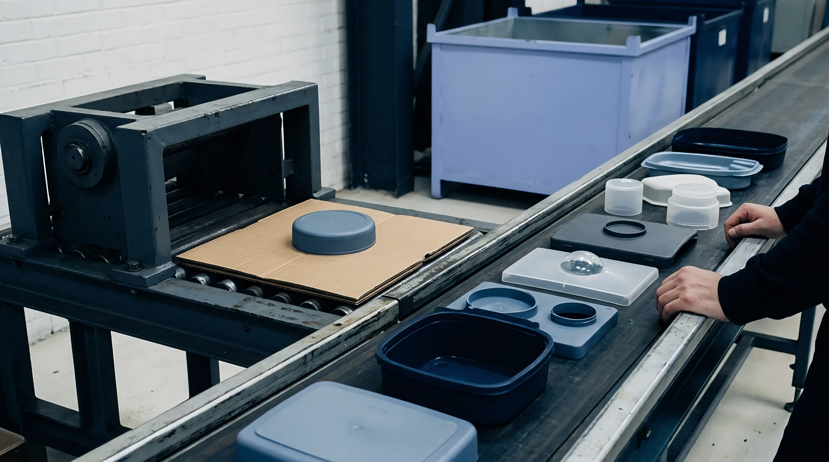

Scan
Exposed tactile foil transitions into actionable quality records via optical metrology. Flatbed image scanners or production vision cameras photograph the pink-to-magenta imprint. Telecentric lens systems prevent perspective distortion, preserving scale across large multi-cavity footprints.
Standard consumer camera lenses induce optical distortion at image margins, bending outer cavity rows and producing spatial errors up to 0.4 mm across a 600 mm mold base.

Vision Architecture and Pixel Conversion
Optical arrays digitize film colour into chromaticity coordinates. Analysis programs separate green light absorption from red channels, since leuco dye absorption peaks between 530 nm and 560 nm. Converting images into calibrated RGB or CIELAB colour space maps optical density directly to pressure values using calibration look-up tables.
Lighting must provide diffuse illumination without directional hot spots that would mimic local steel peaks.
Resolution requirements dictate optical choices. Resolving a 0.2 mm shutoff land requires a pixel footprint no larger than 0.02 mm, demanding an optical resolution exceeding 1200 dots per inch. Optical systems capture both pressure foil colouration and bare steel topography.
Chromatic confocal white-light sensors read surface profiles directly from the mold steel, identifying land height variations before clamping foils.
Non-telecentric optics introduce parallax errors that miscalculate outer cavity shutoff areas by up to twelve percent.
Specular reflection off polished steel complicates non-contact optical inspection. Shutoffs finished to mirror specifications reflect directional light away from camera sensors, appearing as voids. Polarizing filter pairs eliminate surface glare, leaving pure chrominance signals from foil impressions for machine vision processing.

Are Optical Scans Sufficient without Tactile Verification?
Optical measurements of raw steel topography register geometric form without accounting for mechanical deflection under press tonnage. A chromatic confocal scan maps a land flat within 1 µm, yet that same land can lift 15 µm when machine clamp force bows the tool plate. Combining optical topography scans of bare steel with digitized tactile foil impressions links static manufacturing tolerances to loaded working performance.
| Metrology Method | Vertical Resolution | Lateral Resolution | Acquisition Time per Core | Field Environment Tolerance |
|---|---|---|---|---|
| Chromatic Confocal White Light | 0.01 µm | 1.5 µm | 180 seconds | Requires clean tool room bench |
| Telecentric Foil Scanner | 0.80 µm (stress equivalent) | 20.0 µm | 12 seconds | Tolerates press-side lighting drift |
| Coherence Scanning Interferometry | 0.001 µm | 0.5 µm | 300 seconds | Demands vibration isolation table |
| Structured Light 3D Projector | 2.0 µm | 35.0 µm | 5 seconds | Susceptible to steel specular glare |
Edge erosion, microweld cracking, and localized galling show up during optical inspection passes. Automated software identifies pressure dropouts along land perimeters, isolating areas vulnerable to resin leakage. Processing engines apply threshold filters to divide passing land areas from degraded shutoff steel.
The toolmaker guarantees dimensional accuracy to the approved 3D model, asserting that dynamic press deflection falls entirely outside mold construction warranties.

Metric
Digitized pressure maps convert qualitative visual patterns into numbers. Statistical metrics track land health across multi-cavity molds. Contact Area Ratio quantifies the proportion of designed land surface that registers sealing pressure above the critical resin shutoff threshold.
An acceptable shutoff land holds a Contact Area Ratio above 0.92, ensuring continuous sealing borders around every cavity.
Pressure Uniformity Gradient calculates the rate of pressure change across the land width. High gradients signal edge pinching, where sharp corners take destructive loads while inner land regions remain unloaded. When land corners take excessive stress, mold steel deforms, creating flash pathways during sustained production.
- The operator cleans shutoff lands using solvent sprays to remove grease residues, then allows the steel to reach 20 degrees Celsius.
- Technicians insert precision-cut tactile foil across the cavity matrix and jog platens to contact without impact.
- The press applies set clamp tonnage for 120 seconds, opens smoothly, and ejects the foil without mechanical shear.
- Digital imaging systems scan the exposed foil within thirty minutes to limit latent dye bleeding.
- Analysis routines process pixel densities through calibration curves, flagging cavities failing the 60 MPa threshold.
Tolerances under DIN 16742 govern finished plastic parts, but toolmakers work to tighter steel tolerances. Grinding shutoff faces demands flatness within 0.003 mm across individual inserts and 0.010 mm across the entire mold plate. Automated image analysis evaluates these parameters cavity by cavity.
Tool acceptance criteria require every cavity in a high-cavitation layout to show unbroken sealing bands. Gaps wider than 0.05 mm in the pressure band cause rejected parts. Automated algorithms detect these discontinuities, mapping specific cavity numbers to required tool adjustments.
Neglecting quantitative shutoff metrics leads to parting line damage, forcing costly mold rebuilds that interrupt serial manufacturing.
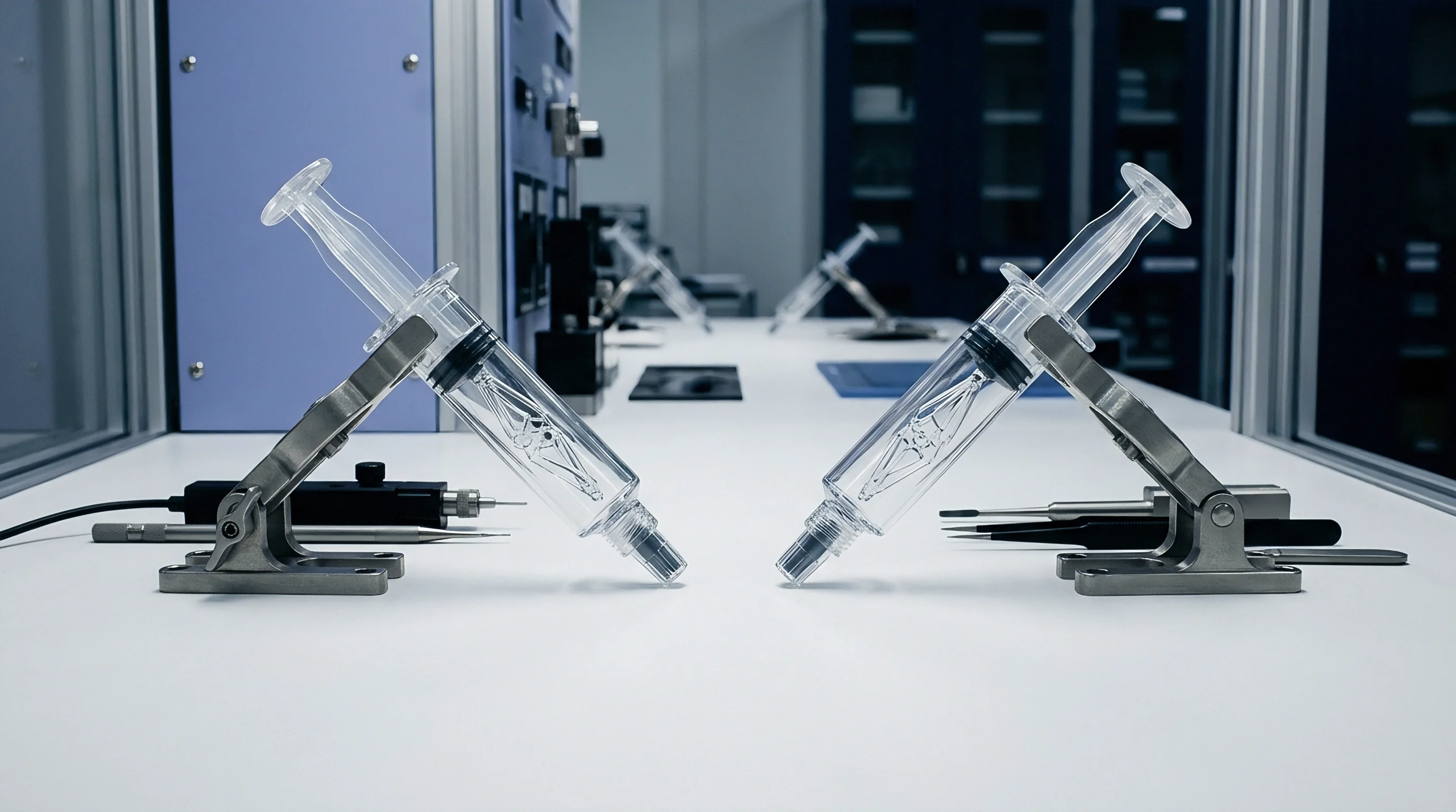
Margin
A tooling quote reflects the hours spent fitting shutoffs. Building a 64-cavity medical syringe tool costs 140,000 euros. Traditional manual spot-fitting consumes 80 hours of bench time.
Automated foil auditing with telecentric optical scanning cuts fitting cycles to 18 hours, saving 6,200 euros in initial toolroom labor. The financial benefit expands during high-volume production runs.
Tooling economics hinge on machine cycle stability. Flash defects stop automated packaging lines, triggering quality holds on entire shifts. Replacing or re-grinding damaged inserts on a high-cavitation tool removes the mold from the press for two weeks, costing 24,000 euros in machine downtime.
Standardized shutoff audits during mold qualification prevent premature steel fatigue.
| Cost Component | Manual Spotting (Blue Paste) | Standardized Digital Metrology | Variance Impact |
|---|---|---|---|
| Initial Fitting Labor | 8,000 EUR | 1,800 EUR | 6,200 EUR reduction |
| Mold Commissioning Dwell | 14 days | 3 days | 11 press days recovered |
| Scrap from Flash Defects | 2.8 percent | 0.3 percent | 18,750 EUR saved per year |
| Emergency Cavity Refurbishment | 12,500 EUR | 0 EUR | Eliminated tool pull |
Flash removal tools cannot touch high-cavitation medical moldings without risking contamination. Scrap parts caused by shutoff wear must be ground or discarded. Establishing quantified contact standards on the tool drawing shields buyers from paying for mold maintenance caused by poor steel fitting.
Supply agreements containing explicit minimum shutoff pressure specifications hold toolmakers accountable for flash performance through warranty runs, securing predictable production costs.

Verdict
Standardizing shutoff land qualification shifts mold sign-off from subjective craft to objective science. Combining calibrated tactile foils with automated optical scanning delivers repeatable records of parting face mechanics under load. Tool drawings must include Contact Area Ratios and minimum sealing pressures alongside traditional dimensional tolerances to govern tool builds.
Buyers commissioning high-cavitation tooling balance the expense of digital metrology against the financial fallout of parting line damage and production scrap. Standardized audit protocols protect tool steel integrity and stabilize cycle performance across millions of shots.
How do micro-scale dynamic thermal gradients shift local land compression during sub-four-second cycles?