Toolroom Blueing Shut off Verification for Injection Moulding
Toolroom blueing shut-off verification proves metal contact under compression to eliminate plastic flash, protect tool steel, and validate parting line pre-load.

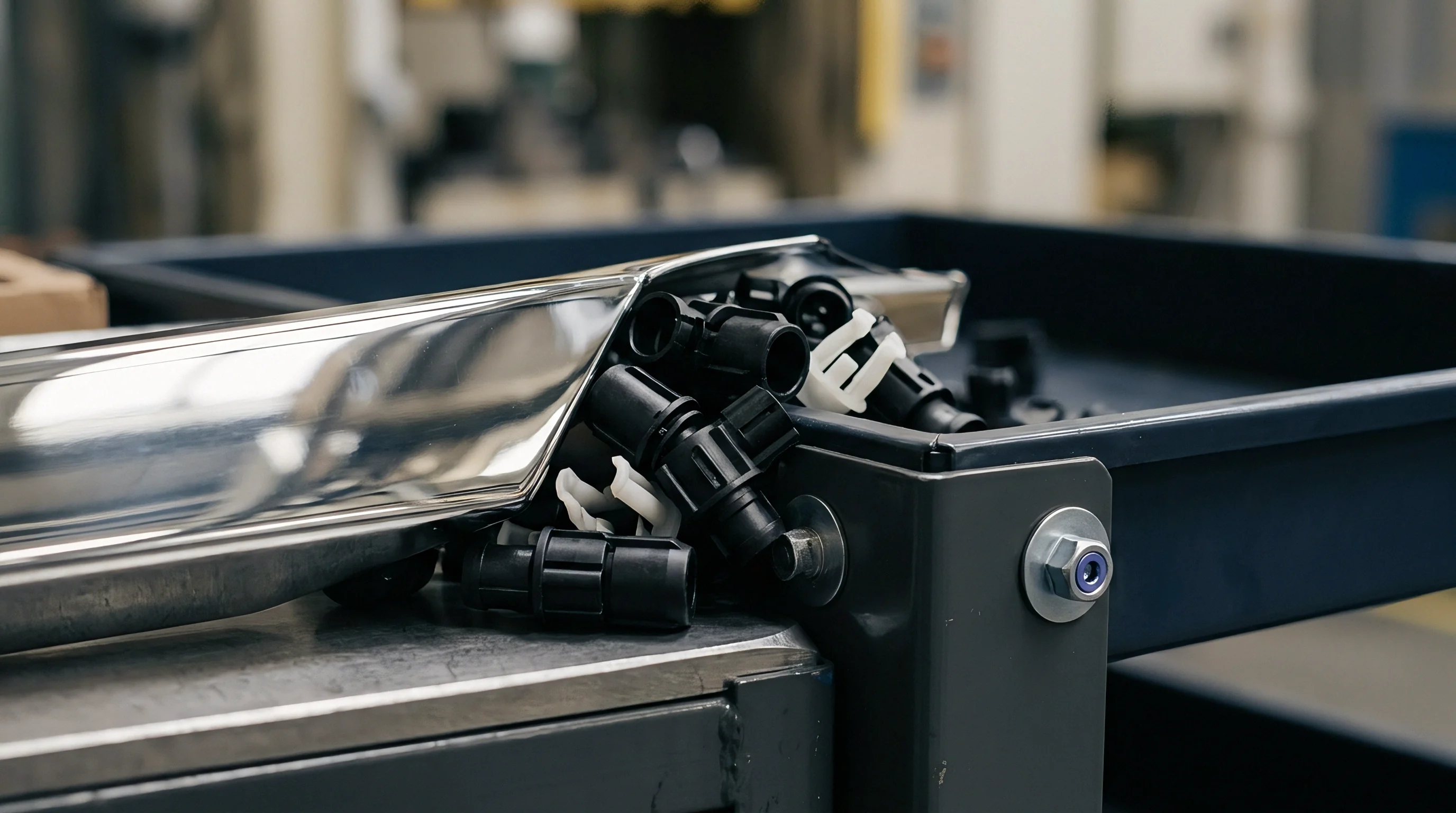
Dye
Toolmaker engineering paste applied to matching mold faces reveals real metallic contact through blue transfer pigment films ranging between two and five micrometers in thickness. Precision mold building relies on this optical transfer method to prove that steel components meet under mechanical compression before plastic resin enters the cavity under injection pressure. Reliance on digital CAD models alone falls short when toolmakers fit parting line lands, slide shut-offs, and internal core-cavity interlocks.
Machining tolerances, heat treatment distortion, and assembly stack-ups create microscopic clearance gaps or excessive local preloads that damage tool steel. Blueing compounds act as a non-compressible fluid indicator, transferring from a coated reference face to an uncoated target face to visually highlight high spots, clearance voids, and contact gradients across critical sealing zones.
Because steel does not yield easily, applying too thick a layer of blueing paste masks structural clearance gaps, generating false transfer marks that deceive bench fitters into over-grinding essential shut-off lands. Precision bench spotting demands a high-viscosity, non-drying paste formulated with ferric hexacyanoferrate suspended in heavy mineral oil or synthetic wax carriers. Toolroom spotting checks require non-drying blue paste with particle diameters below two micrometers.
When the toolmaker brings the mold halves together on bench guiding pins, steel surfaces bearing against one another squeeze the paste outward, leaving intense blue transfer on true high spots while un-transferred regions expose gaps larger than the film itself.

Pigment Layer Physics on Steel Lands
A non-drying mechanical paste transfers under compression to indicate high points across precision shut-off surfaces. The fluid mechanics of blueing pastes govern their fidelity as dimensional measurement tools. If the applied coating exceeds five micrometers, liquid displacement under manual clamp force bridges real physical gaps, indicating seventy percent contact where actual steel engagement remains under thirty percent.
Bench technicians apply the medium using hard felt rollers or short-bristle brushes, wiping the surface with lint-free wipes until only an iridescent, light-blue haze covers the reference land. The thickness of this haze measures approximately two micrometers, matching the allowable flash threshold of low-viscosity polymers such as polyamide 66 and polyoxymethylene.
During bench fitting, the mechanical force pushing mold halves together dictates transfer efficiency. Spotting presses deliver uniform vertical closure forces between ten and fifty kilonewtons, simulating the initial touch-off phase of production molding machines. Direct manual clamping with bench clamps or socket screws frequently introduces side-loading and asymmetric tilt, skewing transfer patterns across long parting lines.
Uneven application of blueing medium causes misinterpretation of parting line contact when evaluating shut-offs for high-pressure injection molding. Toolroom fitters must maintain strict cleanliness protocols, removing ambient dust, oil residue, and grinding grit from tool cavities before applying indicator compounds.
Holding transfer film thickness to two micrometers during bench spotting prevents false contact readings on tool steels hardened to fifty-six HRC.
The visual density of the transferred blueing mark correlates with local compression pressure. Heavy pigment transfer that appears deep navy indicates high contact pressure where steel lands carry the primary clamp load. Faint, patchy blueing signals light touching, sufficient to prevent resin leakage under low injection pressures but vulnerable to flashing under maximum cavity packing loads.
Complete absence of pigment transfer confirms a clearance gap exceeding five micrometers, which mandates precise bench stone dressing or TIG micro-welding to restore sealing integrity.

Preload Forces across Parting Surfaces
Interlocking tool faces demand calibrated mechanical interference to seal against molten polymer at five hundred bar cavity pressure. Parting line lands are designed with intentional standing preload, where shut-off steel projects zero point zero fifteen to zero point zero three zero millimeters beyond nominal mold parting planes. This standing height ensures that under full hydraulic or toggle clamping tonnage, elastic deformation of backing plates and core blocks brings all sealing surfaces into tight contact without crushing core details.
Verification through blueing paste requires iterative assembly and bench fitting cycles to map how this preload distributes across the tool face.
Shut-off draft angles alter how blue paste transfers during tool assembly. Flat shut-offs orthogonal to the press clamp direction experience pure compressive loading, transferring paste cleanly without smearing. Angled shut-offs, designed at five to ten degrees of draft to seal vertical cavity features, experience combined sliding friction and normal compression during tool closure.
Wiping action on steep angles smears blueing paste along the approach vector, obscuring the exact location of initial contact. Toolmakers compensate by applying blueing medium exclusively to the female side of angled shut-offs while leaving the male core clean, observing the leading edge of pigment transfer to verify precise engagement.
Incorrect shut-off preload damages mold steel and compromises part geometry. Insufficient preload leaves clearance gaps that generate flash, requiring secondary manual deflashing operations that add labor costs to part production. Excessive preload concentrates hundreds of metric tons of force onto narrow sealing lands, exceeding the yield strength of tool steels such as P20, H13, or S7.
Crushing of shut-off lands leads to permanent steel deformation, creating permanent flash tracks that demand expensive laser cladding or insert replacement to repair.
| Steel Hardness Grade | Shut-Off Type | Draft Angle (deg) | Target Preload (mm) | Min Blueing Transfer (%) |
|---|---|---|---|---|
| 1.2311 / P20 (30-34 HRC) | Flat Parting Land | 0.0 | 0.015 – 0.020 | 85 |
| 1.2344 / H13 (48-52 HRC) | Flat Parting Land | 0.0 | 0.020 – 0.025 | 90 |
| 1.2083 / 420 SS (50-54 HRC) | Angled Interlock | 7.0 | 0.010 – 0.015 | 95 |
| 1.2379 / D2 (58-60 HRC) | Telescoping Core | 10.0 | 0.008 – 0.012 | 95 |
Interpreting transfer patterns accurately takes a methodical look at pigment distribution, heading off tool damage and flash in high-volume production.
- Excessive pigment viscosity prevents full steel clearance by bridging micro-gaps under light manual assembly force.
- Uneven paste application generates false contact patterns that lead toolmakers to grind correct steel lands away.
- Foreign particle inclusion creates artificial clearance gaps, causing misinterpretation of overall mold closure alignment.
- Incomplete degreasing leaves oil films that repel transfer medium, producing un-transferred spots on perfectly fitted steel.
Light transfer patterns are sometimes dismissed on the assumption that full clamping hydraulic force closes the zero point zero one millimeter gap during high-tonnage production runs.
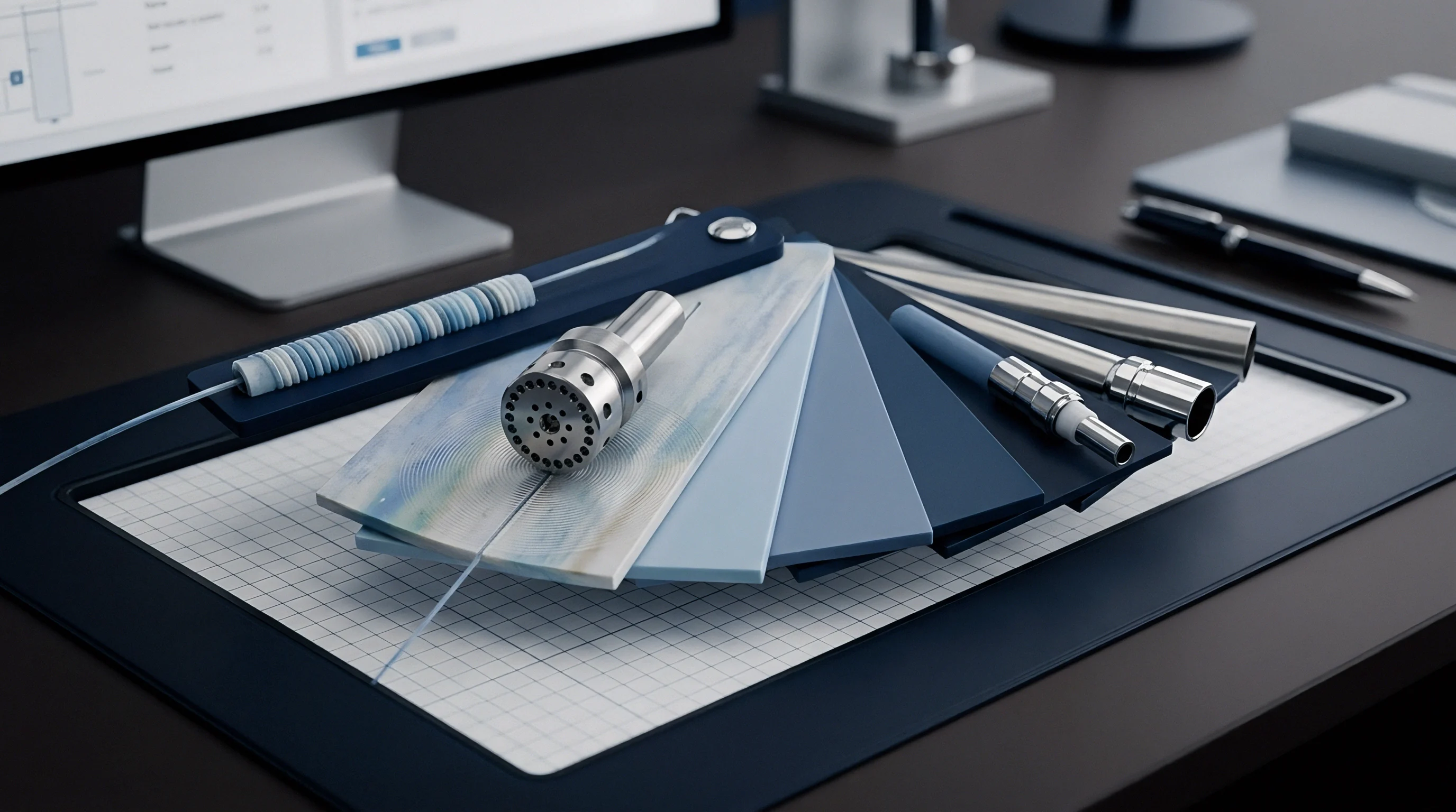

Interlock
Side-action slides and angled core faces mandate precise geometric engagement before main parting line surfaces touch. Interlocking mechanisms govern mold half alignment, preventing side-shifting caused by asymmetric plastic injection pressures. When narrow core pins or tall cavity walls form shut-offs, guiding components like side locks, top locks, and taper locks absorb lateral forces to align mold cavities within zero point zero zero five millimeters.
Blueing verification on interlocks confirms that alignment hardware engages fully before cavity shut-off steels meet, protecting delicate shut-off lands from micro-collisions during rapid press closure.
In multi-cavity injection molds, thermal gradients shift interlock clearances between cold bench fitting and operational mold temperatures. When core and cavity plates run at different temperatures, differential thermal expansion moves the shut-off centers out of alignment. Verification relies on spotting press transfer testing paired with calculated thermal offsets, making sure the interlocks seat correctly without galling or binding once the mold reaches operating heat.

Thermal Expansion Offsets on Angled Steels
Differential thermal growth between cold toolroom benches and warm oil-heated mold bases alters mechanical fit by several hundredths of a millimeter. Standard toolroom assembly occurs at an ambient temperature of twenty degrees Celsius. Production molding of engineering thermoplastics like glass-reinforced polybutylene terephthalate or polyphenylene sulfide runs tool steel temperatures between eighty and one hundred forty degrees Celsius.
Steel expands at approximately twelve micrometers per meter per degree Celsius. Across a six-hundred-millimeter mold base, an eighty-degree temperature rise yields zero point five seven millimeters of expansion across the main parting plane.
If the cavity plate operates twenty degrees hotter than the core plate, the thermal mismatch across shut-off interlocks equals zero point one four millimeters. Angled shut-offs designed with five degrees of draft absorb this thermal expansion by shifting axial contact height. A five-degree shut-off translates zero point one four millimeters of lateral expansion into a vertical shift of one point six millimeters.
Bench fitters must adjust blueing transfer verification targets based on these thermal calculations, ensuring intentional clearance on cold bench spotting checks so that steel faces make contact at operational heat.
| Nominal Distance (mm) | Bench Temp (°C) | Operating Temp (°C) | Delta Temp (°C) | Calculated Expansion (mm) |
|---|---|---|---|---|
| 200 | 20 | 80 | 60 | 0.144 |
| 400 | 20 | 100 | 80 | 0.384 |
| 600 | 20 | 120 | 100 | 0.720 |
| 800 | 20 | 140 | 120 | 1.152 |
Fitters measure core movement relative to cavity plates during bench assembly. Blueing verification of thermal offsets uses step-gauged shims placed under guiding lock wear plates during cold fitting. By shimming interlocks outward by the calculated expansion allowance, fitters verify that blue paste transfers evenly across angled shut-offs only when simulating hot operating geometry.
Telescoping Shut off Clearance Geometry
Vertical sealing faces require minimum seven-degree draft angles to prevent micro-galling during rapid cycling. Telescoping shut-offs feature male core elements entering female cavity recesses to create holes, slots, or passthrough features in molded parts. Unlike flat parting lines that land vertically under compression, telescoping shut-offs slide along one another during the final two to five millimeters of mold stroke.
Blueing paste applied to telescoping lands reveals whether the core enters central to the cavity or leans to one side due to guide pin clearance stack-up.
Angled shut-off faces fitted with seven degrees of draft exhibit zero wiping smear when interlock guiding aligns within five micrometers of true position.
Clearance geometry on telescoping shut-offs must balance plastic flash prevention against metal-to-metal galling risks. Zero-clearance fits on vertical faces scrub away protective lubricating oil films, causing atomic transfer between steel faces that leads to catastrophic tool seizing. Toolmakers land the initial shut-off face across a narrow sealing belt measuring one point five to three point zero millimeters in width, relieving the steel behind this land by zero point five millimeters.
Blueing transfer paste proves that contact remains restricted to the primary sealing belt, confirming that non-contact relief zones remain untouched.
- Clean all shut-off faces with solvent degreaser and lint-free wipes until zero residue remains.
- Apply non-drying engineering paste to the reference half at uniform sub-five-micron thickness using a hard felt roller.
- Close tool under hand pressure on bench guiding pins until core interlocks engage.
- Separate tool halves axially without tilting to prevent wiping of transferred medium.
- Inspect target shut-off lands under ten-times optical magnification to evaluate blueing coverage against engineering drawings.
Telescoping shut-off faces showing zero transfer medium on bench trials will flash resin during shift thermal stabilization.


Press
Bench spotting stands as a static preliminary check, whereas dynamic machine lockup generates localized platen deflection. Modern injection molding presses exert clamping forces ranging from five hundred to over forty thousand kilonewtons to resist plastic cavity pressures. Machine platens flex under these heavy loads, bending outward near the center tie-bar spans.
Mold backing plates follow this platen bending curve, causing the outer edges of mold parting lines to clamp tightly while the center shut-off lands lose compression. Blueing verification conducted on bench spotting presses fails to mirror dynamic platen deflection unless verified under production machine clamping tonnage.
To verify actual shut-off contact under operating tonnage, engineers run press-side blueing trials. Technicians apply a thin film of blueing compound in the toolroom, mount the assembled mold into the production press, clamp it under full tonnage, and immediately part the mold without injecting resin. Reading the pigment transfer under true clamping conditions shows whether platen deflection creates unsealed areas near the center or crushes the steel at the outer corners.
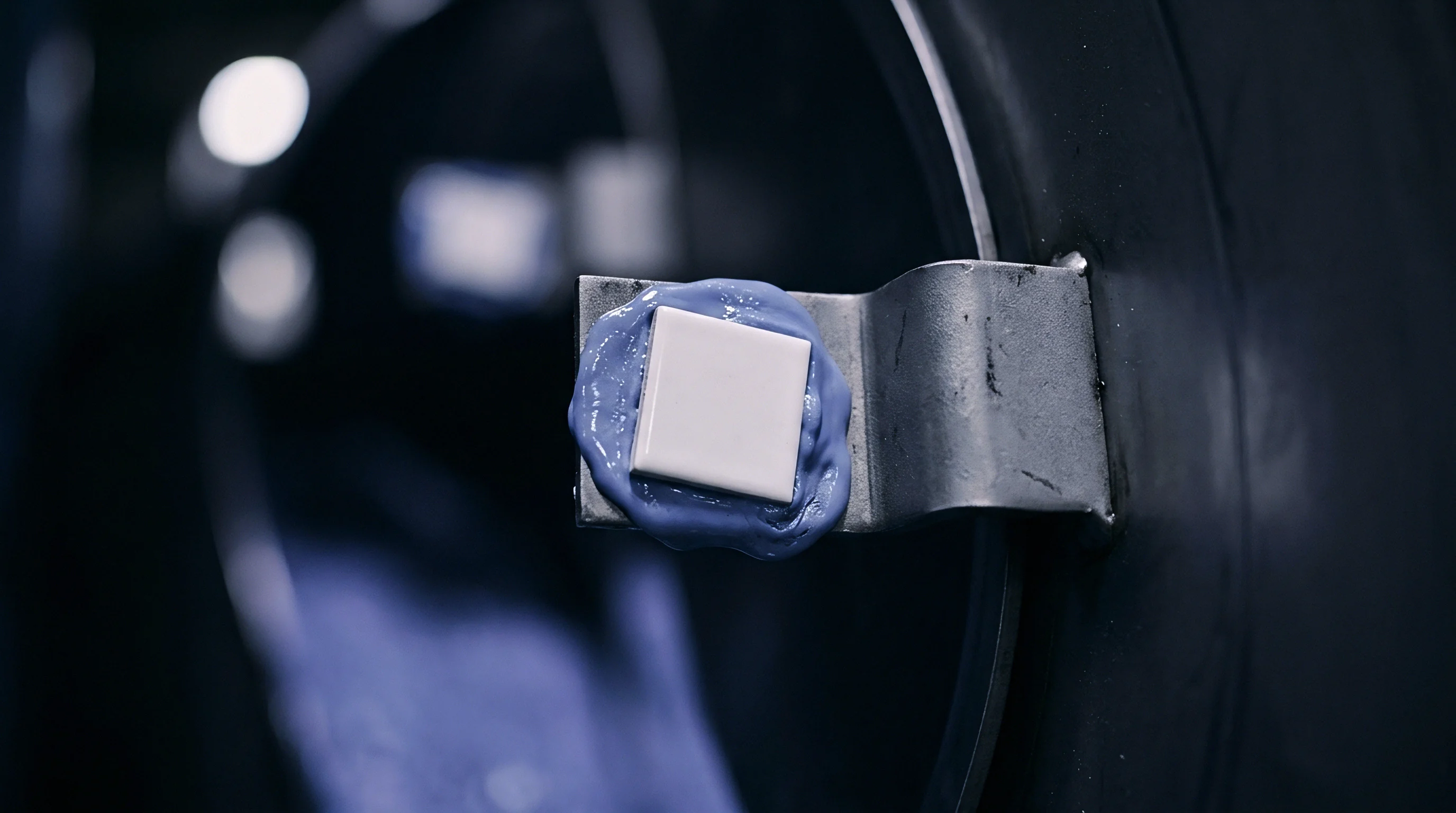
Are Bench Spotting Results Valid under Tonnage?
Hydraulic clamp forces exceeding three thousand kilonewtons flex mold backing plates, altering shut-off contact distributions. Bench spotting presses deliver light vertical closure, typically capping force at fifty to one hundred kilonewtons. This force levels surface asperities but fails to induce structural elastic deformation in heavy steel plates.
When a multi-cavity tool verified on the bench enters a high-tonnage production press, center cavities often yield heavy part flash because central shut-off lands bow away from each other under platen bending.
Comparing transfer patterns between bench conditions and production tonnage highlights structural weaknesses in mold base design. If center shut-offs exhibit hundred-percent transfer on the bench but fade to zero transfer under full press tonnage, the mold backing plates lack sufficient thickness or support pillar density. Engineers insert hardened support pillars directly behind central cavity blocks to resist platen deflection.
Re-testing blueing transfer under full clamp tonnage confirms whether adding support pillars successfully restores uniform shut-off compression across all cavities.
| Clamp Tonnage (% Nominal) | Platen Deflection (mm) | Center Land Transfer (%) | Corner Land Transfer (%) | Observed Flash Height (mm) |
|---|---|---|---|---|
| 30 | 0.005 | 95 | 95 | 0.080 (Low Clamp) |
| 60 | 0.018 | 85 | 98 | 0.035 |
| 80 | 0.032 | 70 | 100 | 0.015 |
| 100 | 0.048 | 45 | 100 (Overloaded) | 0.065 (Center Gap) |
Feeler gauge checks validate non-contact relief areas while blueing paste verifies shut-off lands. Press-side inspection protocols combine chemical indicator transfer with physical gap measurements to ensure tool integrity under high operating pressures.

Feeler Gauge and Optical Verification
Precision thickness shims combined with stereomicroscopic examination verify relief gaps behind sealing lands. Feeler gauges calibrated down to zero point zero one millimeters are inserted into non-shut-off relief pockets while the tool remains clamped under manual lockup on the bench. If a zero point zero two millimeter feeler gauge slips into a shut-off land designed for zero contact clearance, the steel has been over-ground during bench fitting.
Optical stereomicroscopes equipped with ring illuminators inspect the edges of transferred blue pigment, checking for sharp transfer boundaries that signify clean steel contact without edge rounding.
Standard ISO 2768 tolerances mandate that non-contact steel relief clearances hold zero point five millimeters minimum depth to prevent flash traps.
Digital imaging systems replace subjective visual estimates of blueing transfer area. Technicians photograph transferred pigment on shut-off lands using calibrated industrial cameras, running image processing algorithms to quantify exact contact percentages. High-volume automotive tooling specifications require documented proof that shut-off lands maintain over ninety percent blueing transfer across primary parting planes before sample molding trials commence.
- Tonnage scaling verification matches bench transfer patterns against full hydraulic clamp tonnage.
- Platen parallelism check quantifies structural deflection under fifty-bar lockup pressure.
- Thermal equilibrium window establishes shut-off contact at hundred-degree mold operating temperature.
- Feeler gauge cross-check confirms zero gap along non-contact relief zones.
Molding operations absorb twenty-four thousand dollars in rework costs when unverified hydraulic platen deflection causes micro-flashing across eighty-four connector cavities.


Wear
Repetitive clamping cycles degrade precision shut-off lands through continuous friction, localized coining, and resin particulate erosion. Injection molding tools running multi-cavity production execute millions of clamp closures over their operational lifespan. Every stroke drives matching steel shut-offs together, generating micro-scale impacts that flatten sharp steel edges.
Over time, high preload forces induce localized coining, sinking the shut-off land below nominal parting planes. Blueing verification serves as a diagnostic maintenance protocol during tool refurbishments, pinpointing worn sealing zones before part flash causes expensive production line stoppages.
Polymer additives accelerate this degradation. Abrasive mineral fillers, glass fiber reinforcements, and corrosive flame retardants scour steel shut-offs during high-velocity cavity filling. When glass fibers cross shut-off lands during micro-venting or localized flash events, they erode the hard tool steel, carving micro-grooves that destroy sealing capability.
Periodic blueing inspections quantify the rate of land erosion, indicating when steel refurbishment becomes necessary to sustain part quality targets.

Galling Mechanisms on Abrasive Polymer Streams
Thirty percent glass-filled polyamide resins accelerate mechanical degradation at unlubricated sliding interfaces. Melted resin forced into microscopic clearance gaps acts as a grinding compound under high injection velocity. As glass-filled melt passes across parting line shut-offs, high shear stresses drag glass fibers along the steel face, stripping protective oxide films and exposing raw tool steel to atmospheric oxidation and wear.
Galling occurs when unlubricated sliding shut-offs experience metal transfer under high contact pressure. Micro-welding between matching core and cavity steels tears particles out of the surface, creating raised burrs that score opposing steel faces during mold opening. Toolmakers apply physical vapor deposition coatings like titanium aluminum nitride or chromium nitride to shut-off lands, elevating surface hardness above seventy HRC.
Blueing transfer checks on PVD-coated lands confirm that surface treatments maintain dimensional uniform thickness without creating localized high spots that concentrate stress.

Laser Cladding and Stone Refinishing
Toolroom technicians restore worn sealing lands by depositing cobalt-base alloys prior to micro-grinding. Conventional TIG welding introduces extreme thermal energy into tool blocks, generating heat-affected zones that warp surrounding cavity geometry and cause micro-cracking in hardened steel. Laser cladding uses focused optical energy to melt specialized alloy powders onto worn shut-off edges with minimal heat input, restricting heat distribution within zero point two millimeters of the weld deposit.
Following laser cladding, technicians use precision diamond stones and ceramic lap files to re-establish nominal land geometry. Iterative blueing checks guide this manual stone refinishing process. The fitter applies blueing paste, closes the mold on the spotting press, inspects pigment transfer onto the newly welded land, and stone-grinds high spots flagged by dense blue transfer.
This cycle repeats until blueing transfer matches adjacent original steel lands within five percent coverage density.
- High-resolution photographic logs document blueing coverage across every shut-off land at final T1 trial.
- Feeler clearance records map non-shut-off relief areas down to zero point zero two millimeters.
- Dimensional inspection reports link shut-off land contact percentage to part flash measurements.
Standard ISO 20753 tooling compliance contracts mandate zero visual flash above zero point two millimeters after ten thousand continuous automatic cycles.


Audit
Financial sign-off on new injection tooling hinges on empirical proof that shut-off faces hold tight seals without steel damage. Global sourcing practices purchasing high-cavitation production tooling cannot rely on simple verbal assurances from toolmakers regarding shut-off fit. Verifying blueing transfer patterns forms an indispensable milestone within tool commissioning contracts.
Payment structures tie final tool release funds to verified shut-off performance, requiring certified blueing inspection reports and high-resolution photographic evidence recorded during initial tool trials at the supplier facility.
Establishing clear engineering acceptance limits prevents disputes between mold builders and production molding plants. Contracts define acceptable blueing transfer percentages across distinct mold zones: primary parting line lands surrounding part cavities require ninety-five percent continuous transfer, secondary venting lands require eighty-five percent, and outer mold rest pads require eighty percent. Defining these metrics numerically eliminates ambiguous interpretations of manual spotting results, securing long-term tool performance across multi-million-shot production runs.

Tooling Handover Dossier Requirements
Commercial acceptance schedules link final milestone payments directly to verified zero-defect parting line trials. Before an injection mold leaves the toolmaker factory, a formal quality handover dossier must be compiled, approved, and archived. This dossier documents every mechanical fit verification step executed during mold build, assembly, and trial phases.
A primary component of this dossier is the parting line blueing verification log, containing color imagery detailing transfer patterns across all core, cavity, slide, and lifter shut-offs under dry bench lockup and full machine clamping tonnage.
Procurement teams inspect parting line photographic logs before authorizing final tooling payments. Standardized handover protocols demand that blueing verification images accompany CMM dimensional reports, cooling channel pressure decay test logs, and dry-cycle kinematic video files. If photographic logs reveal spotty blueing transfer along critical sealing surfaces, the procurement team withhold final release funds until the toolmaker stone-fits the shut-off lands to achieve specified contact density.
This strict documentation gate protects buyers against inheriting tools that require immediate, expensive mold maintenance upon installation in production plants.
Tool handover contracts requiring documented ninety-five percent shut-off blueing transfer prevent post-delivery mold rework expenses.
Quality management standards like ISO 9001 demand full traceability of tool modifications made during commissioning trials. When blueing checks during T1 trials reveal shut-off flash, all subsequent steel adjustments, laser cladding repairs, or stone dressing operations must be recorded in the tool engineering history log. This record provides maintenance engineers with baseline fit data when executing future tool overhauls or troubleshooting flash defects after millions of molding cycles.

Cavitation Amortization and Flash Risk
Multi-cavity molds multiply shut-off failure risk, turning subtle steel crushing into rapid cavity deactivation. In high-cavitation tooling producing medical components or caps and closures, mold bases contain sixty-four, ninety-six, or one hundred twenty-eight identical cavities. A failure in shut-off fit on a single cavity forces setters to shut off that individual cavity stream or remove the entire mold from production for toolroom repair.
Downed cavities decrease production yields while maintaining constant machine hour costs, inflating piece prices and eroding tooling investment payback models.
Tool amortizations rely on predictable, uninterrupted cycle execution at quoted production speeds. Flashing caused by bad shut-off seals damages parts and risks tool steel damage if flashed plastic crushes between mold faces on subsequent automatic cycles. Mold damage protection sensors detect crushing hazards only down to zero point one millimeter, whereas plastic flash as thin as zero point zero two millimeters can crush shut-off steel under full clamping tonnage.
Rigorous blueing verification during tool build remains the single most effective preventive measure against premature shut-off crushing and unexpected tooling write-downs.
Cost modeling demonstrates the economic return of thorough toolroom blueing verification. Spending thirty hours of skilled toolmaker bench fitting time during initial assembly adds approximately three thousand dollars to upfront tooling costs. Supplying a mold with unverified shut-offs that flashes during production runs causes secondary manual deflashing, unscheduled mold maintenance, machine downtime, and scrap generation that easily exceeds fifty thousand dollars within the first three months of production.
Upfront shut-off verification secures capital investment, protects gross margins, and verifies that production tooling delivers flash-free parts throughout its contractual lifetime.
Tooling buyers remain divided over whether non-contact blueing clearance measurements ought to be re-verified at fifty thousand cycles or reserved exclusively for major refurbishment intervals.