Calculating Thermal Expansion and Clamping Loads in High Cavitation Moulding
Calculated thermal expansion along tool plates dictates guide pin clearances and shut-height clamp adjustments required to prevent parting line damage.


Expansion
Thermal Mass and Dimensional Shift in Large Multi-Cavity Tooling
High cavitation moulds containing 64, 96, or 128 cavities present extreme physical dimensions where heat distribution governs structural geometry. Steel expands under heat. A tool steel plate measuring 1,000 millimetres in width experiences substantial physical movement as its internal temperature rises from ambient room condition to steady-state moulding temperatures.
Tooling steel grades commonly used in high-production moulding, such as 1.2344 (H13) tool steel or 1.2083 (420 stainless steel), possess precise coefficients of thermal expansion ranging between 10.5 and 11.8 micrometres per metre per degree Celsius. When a tool plate heats from a cold bench state of 20°C to an operational temperature of 140°C for engineering polymers, a 1,000-millimetre plate expands laterally by more than 1.2 millimetres across its outer cavity centers.
When tool designers position cavities across an extended pitch, thermal growth directly dictates the positional accuracy of nozzle touches, gate alignments, and interlocking core pins. Cavities located near the central geometric axis of the platen experience minimal spatial displacement relative to the main runner feed. Cavities located at the outer perimeter move outward systematically.
If the stationary hot runner manifold plate operates at 280°C while the adjacent cavity plate operates at 80°C using water cooling channels, a differential thermal expansion gradient forms immediately across the assembly interface.
At an operating temperature delta of 200°C, a 1.2344 steel hot runner manifold expands by 2.36 millimetres over a 1,000 millimetre length against its supporting cavity plate.
Manifold drop nozzles must slide across cavity gate seats or utilize floating dowel systems to accommodate this lateral travel without shearing gate seals. Miscalculating this growth leads to nozzle offset, melt leakage behind the manifold, or severe bending forces on nozzle tips. Moulders attempting to start a high-cavitation tool before the hot runner and tool plates achieve thermal equilibrium risk immediate metal-to-metal galling on side slides and guide pillars.
| Steel Grade | Standard Classification | Coefficient of Thermal Expansion (10⁻⁶/K) | Thermal Conductivity (W/m·K at 100°C) | Plate Expansion at 1,000 mm (20°C to 120°C) |
|---|---|---|---|---|
| 1.2311 / 1.2312 | P20 Pre-hardened | 12.2 | 33.0 | 1.22 mm |
| 1.2344 | H13 Premium Tool Steel | 11.5 | 26.3 | 1.15 mm |
| 1.2083 | 420 Stainless Steel | 10.6 | 23.8 | 1.06 mm |
| Ampcoloy 940 | Beryllium Copper Alloy | 17.5 | 208.0 | 1.75 mm |
Heat transfer through large steel structures is non-linear during initial startup phases. Outer plate boundaries cool through air convection and radiation while internal zones remain hot due to continuous melt injection. Thermal imaging reveals temperature differentials up to 35°C between plate centers and external corners unless specialized variable-spacing cooling circuits maintain uniform heat removal.
The clamp holds fast.
Tooling plates experiencing non-uniform thermal distribution suffer from bowing or dish-shaped warpage. This curvature introduces unequal clamp force transmission across the parting line. Center cavities receive excessive pre-load pressure while corner cavities experience reduced parting line seal, producing severe part flash along perimeter cavities during high-pressure injection phases.
Ignoring plate expansion calculations destroys parting line shut-off faces within the first fifty thousand moulding cycles.
Growth

Interference Mechanics and Alignment Systems under Thermal Gradients
Maintaining precision register between moving and stationary mould halves requires rigorous calculation of differential temperature profiles. Cold steel resists force. In fast-cycling thin-wall container moulds, the fixed side hot runner manifold runs at elevated temperatures, transferring heat into the fixed cavity plate.
The moving core plate relies on high-velocity chilled water at 10°C to strip heat from the moulded part, keeping the moving plate significantly colder than its fixed counterpart. A temperature differential of 60°C between the fixed plate and moving plate shifts leader pin locations relative to their mating bushings.
Interference fits on alignment components lock up when guide pins cross thermal gradients without adequate running clearance. Standard guide pillars sized at 50 millimetres in diameter experience micro-scale expansions, but the spatial pitch between opposing guide pillars expands along the full width of the plate. If the fixed plate expands by 0.50 millimetres while the moving plate expands by only 0.12 millimetres, guide pins bound inside bushings during stroke movement, causing severe scuffing or catastrophic tie-bar binding.
Can Thermal Growth Misalignment Shear Mold Core Pins?
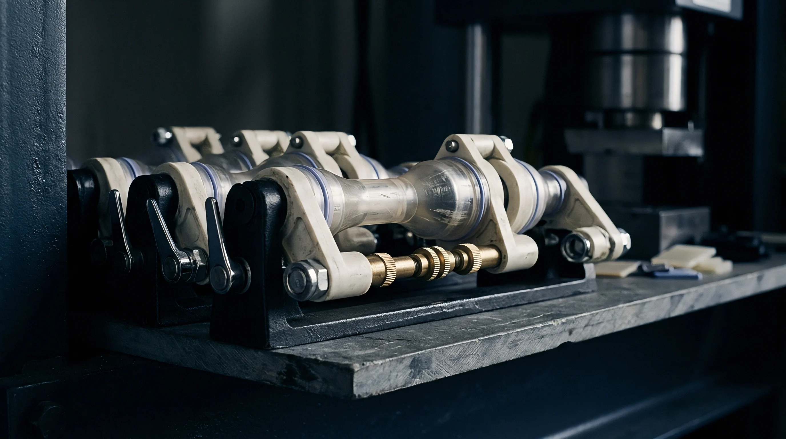
Precision core pins forming small features, such as medical luer locks or pipettes, feature diameters under 1.5 millimetres. When fixed side cavities shift position relative to moving side core pins due to plate growth differentials, the core pins enter the cavity off-center during tool closure. Core pins bend first.
Bending forces exceeding the material yield limit produce permanent core deflection, wall thickness variations in the part, or complete shearing of the core pin during final lock-up.
- Interlocking tapered locks absorb lateral alignment shifts by utilizing angled precision wear plates mounted on external tool faces to center the mould before cavity entry.
- Guided ejector plates require separate thermal allowance clearances to prevent core pin binding within the backplate during high-temperature operation.
- Floating cavity inserts utilize ground pockets with engineered thermal growth gaps, allowing individual insert centers to adjust independently against the main frame.
- Thermally decoupled leader bushings incorporate insulated mounting flanges to prevent thermal energy transfer from hot plates directly into alignment shafts.
Tolerances defined under ISO 286 for precision sliding fits fail when operating temperatures alter component diameters beyond two hundredths of a millimetre.
Side action slides and lifter mechanisms experience acute operational problems under thermal growth. Internal slide components reach higher temperatures than outer retaining gibs due to direct contact with fresh melt. Tight fits cause binding.
When internal slide units expand faster than external gib rails, the clearance vanishes entirely, leading to mechanical galling. Toolmakers forced to repair damaged slide tracks often cite improper lubrication rather than acknowledging thermal growth calculations that lacked sufficient operational clearance allowances.


Tonnage

Melt Pressure Integration and Thermal Lockup Load Requirements
Determining total clamping force for high cavitation tooling involves calculating both plastic melt hydraulic force and thermal pre-load growth. Melt pressure drops downstream. Injection pressure inside the cavity during peak packing phases reaches between 300 and 800 bar, depending on polymer viscosity and flow length to wall thickness ratios.
Multiplying projected cavity area by internal cavity pressure yields the raw hydraulic opening force that the injection press clamp must overcome.
High cavitation moulds concentrate tremendous total projected areas across large platens. A 96-cavity closure mould with individual cavity projected areas of 700 square millimetres presents a total polymer projected area of 67,200 square millimetres. At a peak packing pressure of 600 bar (60 N/mm²), the polymer melt exerts an opening force of 4,032 kilonewtons, equivalent to 411 metric tonnes of opening pressure.
Hot runners grow outward.
In addition to melt opening force, thermal growth introduces a physical length change along the shut-height axis of the mould. As the tool heats inside the press, its stack height increases along the z-axis between machine platens. On mechanical toggle clamping machines, a tool stack height increase of 0.35 millimetres due to thermal expansion dramatically elevates the final clamping load beyond the machine’s rated capacity.
- Calculated required hydraulic clamp force based on total projected cavity area and maximum packing pressure.
- Added 15 percent safety factor for cold runner and hot runner nozzle tip pressure spikes during cold start phases.
- Measured exact tool stack height at cold ambient temperature using external laser micrometers across four corners.
- Calculated axial thermal expansion along the z-axis using thermal expansion coefficients for the total steel thickness.
- Adjusted press die-height position during warmup to maintain constant tie-bar strain readings as tool temperature rises.
Excessive clamping force causes tie-bar stretch, platen deflection, and permanent crushing of parting line land areas. Land crushing eliminates air vents, leading to short shots, diesel burning of the polymer, and excessive burrs along part edges. Clamp force settings left unmonitored during hot tool installation cause toggle mechanisms to lock over center with force levels capable of cracking casting platens.
Process setters frequently encounter parting line flash along central cavities while outer cavities show no flash. Moulders often respond by increasing hydraulic clamping force, escalating the structural damage. The central flash occurs because high central cavity pressures cause localized elastic deflection of the mould plates, opening a micro-gap despite high total clamp tonnage on the machine frame.
What structural stiffness threshold prevents plate separation under central melt forces remains a subject of ongoing investigation among tool designers.

Arithmetic

Step-by-Step Thermal Expansion and Clamp Load Calculation
To demonstrate structural calculations, consider a 128-cavity medical tube cap mould constructed from 1.2344 steel. Assume the following design parameters: total plate width along the x-axis is 800 millimetres, total plate height along the y-axis is 800 millimetres, and total tool stack height along the z-axis is 600 millimetres. The cold tool sits at a baseline temperature of 20°C. Steady-state operating conditions bring the cavity plates to 90°C using hot oil circulation, while the hot runner manifold reaches 260°C.
First, calculate the linear thermal expansion of the cavity plate along its width. The formula for linear thermal growth is ΔL = L₀ × α × ΔT. Here, L₀ represents the initial length of 800 millimetres, α for 1.2344 steel is 11.5 × 10⁻⁶ / K, and ΔT is 90°C minus 20°C, which equals 70 K. Applying these numbers yields ΔL = 800 × (11.5 × 10⁻⁶) × 70, resulting in a lateral expansion of 0.644 millimetres across the plate width.
Next, compute the axial growth along the z-axis that impacts machine clamp shut-height. The tool stack consists of 450 millimetres of cavity and backing plates operating at 90°C, and 150 millimetres of manifold plate area operating at an average localized temperature of 180°C. For the cavity plates: ΔL_cavity = 450 × (11.5 × 10⁻⁶) × 70 = 0.362 millimetres. For the hot runner zone: ΔL_manifold = 150 × (11.5 × 10⁻⁶) × 160 = 0.276 millimetres.
Summing both values gives a total stack height growth ΔZ_total of 0.638 millimetres.
| Calculation Phase | Physical Variable | Input Value | Derived Output Value | Operational Implication |
|---|---|---|---|---|
| X/Y Axis Thermal Shift | Plate Length / Delta T | 800 mm / 70 K | 0.644 mm expansion | Requires floating guide pin clearances |
| Z-Axis Axial Growth | Stack Height / Delta T | 600 mm / Combined | 0.638 mm expansion | Demands die-height opening before heat-up |
| Hydraulic Melt Force | Area / Cavity Pressure | 128 cavities × 380 mm² @ 650 bar | 3,161.6 kN (322.3 tonnes) | Minimum static hydraulic clamp floor |
| Tie-Bar Strain Pre-Load | Platen Displacement Modulus | 0.638 mm shut-height change | +142.5 tonnes forced pre-load | Exceeds 400-tonne machine limit if static |
Now evaluate the clamp force requirements. Each tube cap cavity has a projected area of 380 square millimetres. Total polymer projected area across 128 cavities equals 48,640 square millimetres.
Assuming a peak packing pressure inside the cavity of 650 bar (65 N/mm²), the melt opening force equals 48,640 mm² × 65 N/mm², which yields 3,161,600 newtons, or 322.3 metric tonnes. Adding a standard cold runner/sprue projected area contribution of 12 percent increases the required hydraulic separation resistance to 361 tonnes.
If the machine die-height remains fixed at cold tool setup, the 0.638 millimetre z-axis thermal growth compresses the platens and stretches the four tie-bars. On a typical 400-tonne injection moulding press with a tie-bar spring constant of 223 tonnes per millimetre, a shut-height increase of 0.638 millimetres generates an unintended thermal pre-load force of 0.638 mm × 223 tonnes/mm = 142.3 additional metric tonnes. Adding this thermal pre-load to the baseline clamping set-point overloads the frame, risking structural fatigue failure of press tie-bar threads.
Press tie-bar load cells must read real-time strain under DIN EN 201 testing standards to prevent mechanical clamp over-pressurization during heating cycles.
Under formal procurement specifications governed by standard tooling supply contracts, suppliers must state cold tool dimensions alongside calculated hot operating dimensions. Failure to document predicted z-axis thermal growth in the tool dossier voids machine platens warranties if mechanical overload occurs during factory acceptance testing.

Deflection

Platen Deformation Dynamics and Shift-Length Process Stability
Injection press platens deform under load rather than behaving as infinitely rigid solid blocks. Platens flex under center loads. When a high cavitation mould transfers hundreds of tonnes of clamp force through its outer backing plates, the press platen experiences elastic bending along its central span.
The platen center bows away from the mould backing plate by distances ranging between 0.05 and 0.20 millimetres under full tonnage.
Platen flexure changes the clamping force distribution across the parting line. The outer perimeter of the mould receives excessive compressive force, while the central cavities experience reduced shut-off pressure. Coupled with the internal melt pressure pushing outward, central cavities flash continuously while perimeter parts remain dimensionally undersized due to crushing of their parting line vents.
Flash signals low tonnage.
Tie bars carry the strain. Electric injection moulding machines utilize digital strain gauges mounted directly on each tie-bar to measure structural elongation in real time. If the mould expands non-uniformly due to asymmetrical water cooling lines, the upper tie-bars experience higher tensile loads than the lower tie-bars.
Modern press control systems automatically adjust individual tie-bar nut positions or issue alarms when strain imbalance exceeds five percent across opposing frame corners.
Process drift across a twelve-hour night shift traces back to gradual thermal saturation of the machine platens and hydraulic fluid. Temperature offsets alter tool height. As heat transfers from the mould backing plates into the cast iron press platens over hours of continuous operation, the platens themselves expand, altering the pre-set clamping gap.
A platen temperature increase of 15°C introduces enough dimensional growth to add 30 tonnes of unintended clamp force on fixed die-height toggle presses.
Good tooling survives heat. Press setters manage shift drift by establishing closed-loop tie-bar strain control. Closed-loop control systems continuously monitor strain readings and adjust the machine die-height motor in increments as small as 0.01 millimetres, maintaining a constant effective clamping tonnage regardless of thermal growth within the mould or press frame.
Moulders using older hydraulic presses without automated tie-bar monitoring must implement routine shut-height recalibration schedules. Recalibrating die-height after the tool operates at full temperature for two hours ensures that clamping loads match initial calculations rather than running under destructive thermal over-compression.


Audit

Verification Protocols and Commercial Sourcing Risk Management
Procuring high cavitation tooling requires detailed verification of thermal expansion models before steel cutting begins. Buyers inspecting tool drawings must demand explicit engineering calculations covering manifold thermal movement, plate growth allowances, and projected clamping tonnages under peak melt pressure. Approving a tool design without verified thermal expansion calculations transfers financial liability for tool failure directly from the toolmaker to the purchasing entity.
Dimensional compliance standards such as DIN 16742 set strict tolerance bands for injection-moulded plastic parts. Grade TG3 tolerances require cavity dimensions to hold limits within hundredths of a millimetre. Holding TG3 tolerances across a 128-cavity tool is impossible if thermal expansion causes cavity centers to shift relative to core centers during production runs.
Tooling qualification protocols must mandate an eight-hour continuous thermal stability trial during initial Factory Acceptance Testing (FAT). The tool must run at target cycle times without pause while real-time sensor arrays log plate temperatures, tie-bar strain loads, and parting line separation values. Any requirement to increase clamping tonnage above calculated levels to stop central parting line flash indicates structural plate deflection caused by uncompensated thermal expansion.
Commercial contracts for high-cavitation tooling must include explicit warranty protection against thermal galling and parting line crushing. A robust tooling procurement clause specifies that the toolmaker bears full cost for replacing damaged cavity inserts, crushed vent lands, or galled sliding components if failure occurs under specified operating temperatures and within approved clamping tonnage limits.
Signing off on high-cavitation tooling requires verifying that physical press capacity aligns with total calculated loads. Buyer procurement teams must cross-check press tie-bar spacing, platen deflection charts, and automated shut-height control capabilities before allocating a hot runner tool to a specific production facility. Validating these mechanical and thermal calculations prior to tool sign-off guarantees long-term process capability, protects capital tooling investment, and eliminates costly night-shift downtime.