Thermal Resistance Basics in Textured Plastic Injection Molds
Textured mold cavity thermal resistance stems from trapped micro-air gaps, reducing interfacial heat transfer coefficients down to 800 W/m²K and extending cooling cycle duration.
Boundary
Microscopic Surface Asperities and Microair Trapping
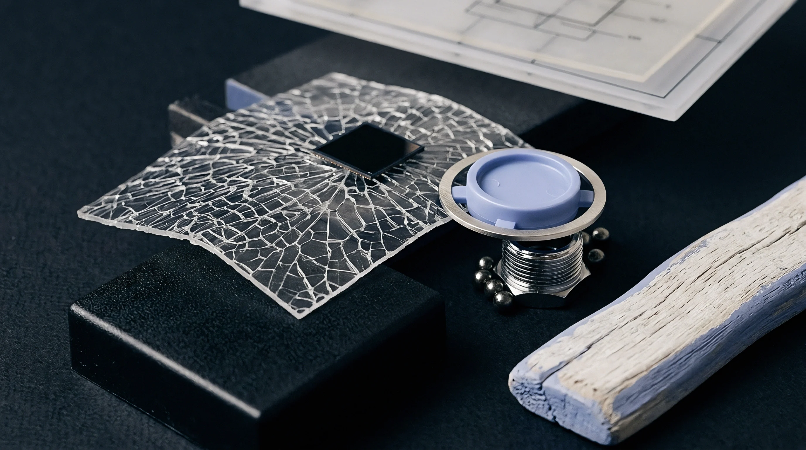
Polymer solidifying against a textured cavity faces conditions far different from those in a polished steel tool. Chemical acid graining, spark-erosion EDM finishes, and femtosecond laser ablation create microscopic peaks and valleys across mold steel, with profile depths ranging from 6 microns on fine textures up to 120 microns on coarse automotive patterns. As molten resin flows over these asperities, its surface tension and shear-dependent viscosity resist immediate wetting into narrow valleys.
High-velocity injection propels the melt front across texture peaks, trapping pockets of cavity gas before hydrostatic packing pressure can develop fully.
Static air locked within micro-valleys has a thermal conductivity near 0.026 W/m K, compared to 24 to 34 W/m K for tool steel alloys like P20 or H13. This trapped air forms an insulating barrier between the plastic and the steel, so real solid-to-solid contact during initial filling often covers less than 20 percent of nominal surface area. Thermal dissipation across this composite boundary drops sharply relative to a smooth tool, causing mold designers who rely on uniform heat transfer coefficients to overestimate cooling rates in textured zones.
Micro-asperity geometry dictates early skin formation physics. Sharp peaks on EDM finishes act as localized thermal conductors, rapidly cooling isolated spots of resin while adjacent micro-valleys retain melt heat. Chemical graining produces rounded valleys that alter friction and local velocity.
Laser-ablated textures present steep sidewall draft angles that trap air pockets when the melt front moves parallel to the grain orientation. Mounting thermocouple probes directly behind the textured cavity wall allows analysis of the interfacial contact area, confirming that early thermal transfer drops sharply as micro-roughness depth increases.
The boundary layer determines local polymer freezing rates. Rapid heat dissipation through polished steel creates a dense, highly oriented skin within milliseconds of contact, whereas textured surfaces delay initial skin freeze by holding elevated temperatures at micro-valley contact points. High-viscosity polymers, including glass-filled polycarbonate and structural polyamide grades, resist micro-valley penetration under low cavity pressure.
These micro-void networks persist throughout injection, maintaining a thermal bottleneck until packing pressure forces the viscous polymer into the texture recesses.
Defining Interfacial Thermal Resistance
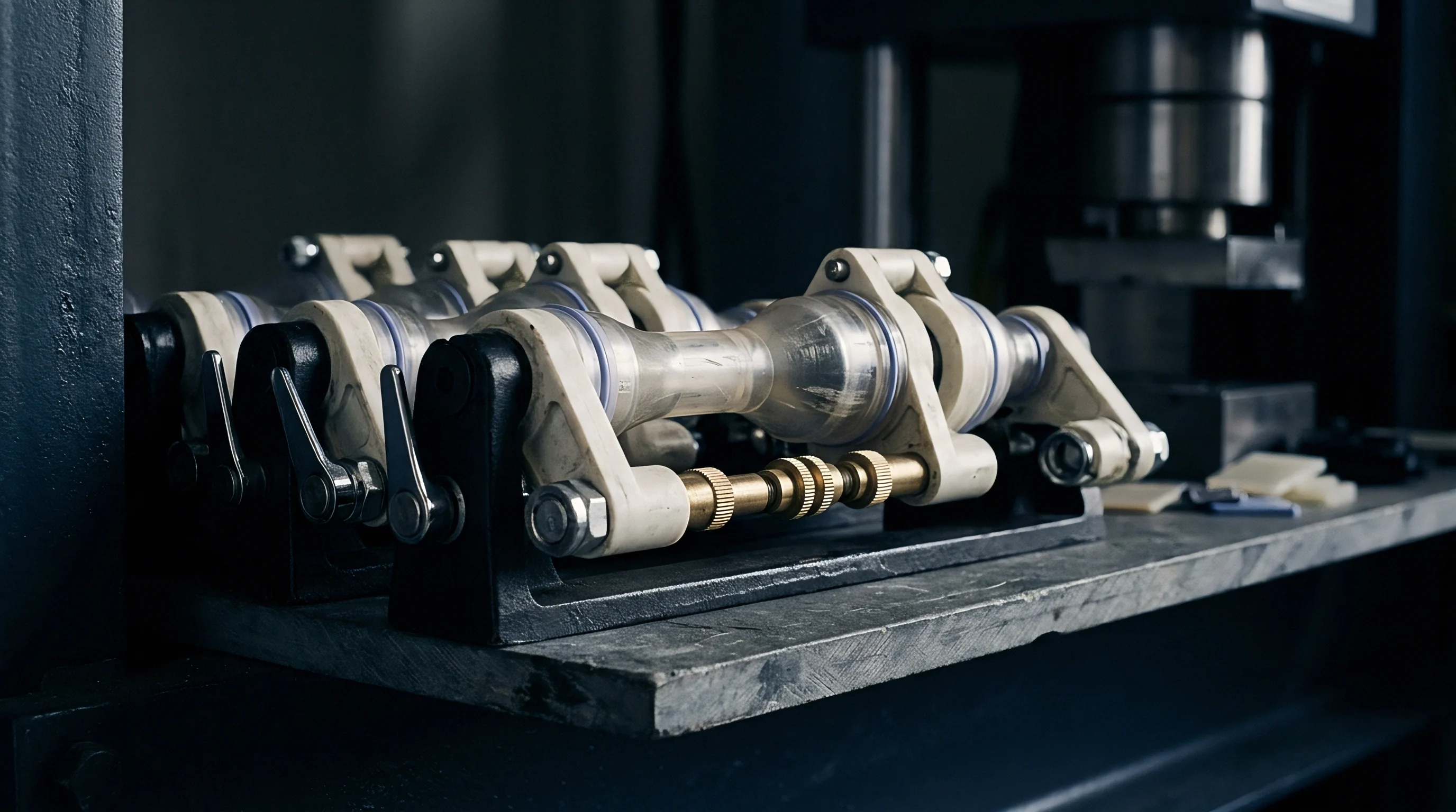
Interfacial thermal resistance quantifies the temperature drop across the contact zone between polymer melt and tool steel for a given heat flux. Expressed directly as thermal contact resistance or inversely as the interfacial heat transfer coefficient, this parameter acts as added thermal impedance in series with mold steel conduction and internal plastic heat transport. Standard thermal modeling software often treats mold surfaces as continuous contacts with constant heat transfer coefficients between 2000 and 4000 W/m²K. Textured surfaces disrupt this assumption, as dynamic heat transfer coefficients drop to between 600 and 1500 W/m²K during early packing.
Trapped micro-air pockets within chemical texture valleys reduce true solid-to-solid contact area between polymer melt and tool steel.
Total thermal impedance at the textured interface combines two parallel dissipation paths: direct conduction through localized steel-to-polymer contacts across micro-asperity peaks, alongside conduction through trapped air pockets and radiation across microscopic gap voids. Mathematically, effective interfacial resistance equals the reciprocal sum of these component conductances. Solid-to-solid contact points dominate heat flux when high cavity packing forces resin against peak summits, whereas air gap conduction takes over inside deep texture valleys where cavity pressure fails to overcome surface tension.
Polymer skin formation alters contact dynamics throughout the cycle. Liquid resin initially exhibits low contact resistance as fluid stress forces melt against micro-features. Rapid cooling then increases resin yield stress, forming a semi-rigid skin within tenths of a second.
This solidifying skin resists further physical deformation under hold pressure, locking micro-gaps between the skin and micro-valley baselines in place. Thermal resistance remains elevated throughout solid-state cooling, slowing heat removal from the part interior until mold opening.
Ignoring interfacial contact resistance leads directly to mispositioned cooling channels, localized warpage, extended cycle times, and gloss variations across textured show surfaces.


Gap
Dynamic Contact Pressure and Viscous Melt Inflow
Contact pressure within the cavity changes through all four phases of the molding cycle. Injection begins at low pressure as resin fills open volume, bridging micro-peaks without invading deep texture grooves and leaving air gaps intact. Pressure rises exponentially as the mold fills and transitions to holding pressure, where levels between 200 and 800 bar compress trapped gas pockets and force solidifying resin into micro-valleys.
Polymer displacement into these grooves increases true contact area from under 20 percent initially to peak values around 85 percent.
Melt viscosity dictates how far resin penetrates into micro-features during holding pressure. High melt flow index resins fill fine texture valleys under modest cavity pressure, while low melt flow index polymers and heavily filled compounds resist deformation, requiring substantial holding pressure to collapse micro-air gaps. As thermal contraction begins, viscoelastic recovery within the cooling resin generates restoration forces that oppose hold pressure, pulling polymer away from sharp sidewalls.
Volumetric shrinkage during cooling causes physical separation between the plastic skin and cavity walls. Internal contraction pulls the part away from texture features, particularly on core-side textures or shallow geometry lacking adequate packing pressure. Cavity pressure drops toward atmospheric levels as gate freeze-off occurs.
Contact area decays rapidly once hold pressure drops, expanding micro-air gaps between skin and steel and returning cooling mechanics to an air-gap dominated thermal resistance state during late-stage cooling.
Interfacial Heat Transfer Variations over the Cycle
Interfacial heat transfer coefficients on textured mold surfaces track cavity pressure history over time, producing a characteristic bell-shaped curve. Initial melt contact yields low values near 800 W/m²K due to incomplete wetting. Pressure build-up during packing elevates heat transfer coefficients to peak values between 2500 and 3500 W/m²K on medium grain textures.
Once the gate seals, pressure drops and thermal contraction reduces contact pressure, pulling late-stage heat transfer coefficients back below 1000 W/m²K before mold opening.
Amorphous polymers present different contact resistance profiles than semi-crystalline polymers. Polycarbonate and ABS soften gradually through their glass transition, allowing hold pressure to maintain contact area over a wider temperature range. Polypropylene and polyamide undergo rapid crystallization at specific thermal thresholds; this sudden phase change drives prompt volumetric contraction, triggering early detachment from micro-valleys and accelerating micro-gap expansion early in the cooling phase.
Surface tension reinforces heat insulation by preventing liquid resin from wetting micro-cavity root radii without sufficient driving pressure. High surface tension resins form high contact angles relative to mold steel, trapping spherical air bubbles at valley bottoms. Raising melt temperatures lowers polymer surface tension and improves physical wetting, reducing initial gap size and baseline contact resistance before packing pressure is applied.
Surface Defect Manifestations in Grained Cavities
Interfacial thermal contact resistance variations across textured surfaces drive several distinct quality failures in precision injection molding operations.
- Differential gloss bands develop on show surfaces where cavity pressure variations create unequal contact area, resulting in uneven cooling rates and distinct reflectivity zones.
- Localized sink marks form behind thick structural ribs when thermal resistance at the textured surface retards heat removal from the outer skin, keeping internal resin molten while adjacent thin walls freeze.
- Ejection scuffing marks occur when incomplete thermal dissipation leaves the polymer skin soft, allowing deep texture peaks to shear plastic during ejection.
- Weld line notch weakness intensifies in textured zones because delayed heat removal prevents polymer chain entanglements from consolidating before the melt front freezes.
- Tiger stripe flow lines emerge when alternating contact resistance zones cause cyclic melt freezing and hesitation along advancing flow fronts across coarse grain patterns.
Surface gloss variations on textured parts can stem from inconsistent bead blasting grit sizes during graining rather than solely from underlying cavity heat transfer dynamics.


Flux

Transient Heat Conduction and Cooling Kinetics
Heat transfer through mold walls follows transient conductive mechanisms governed by Fourier’s law coupled with interfacial boundary conditions. One-dimensional heat flux through the mold interface equals the interfacial temperature drop multiplied by the dynamic heat transfer coefficient. Polymer thermal conductivity is low across technical resins, typically between 0.15 and 0.35 W/m K. High internal thermal resistance within the plastic wall acts in series with contact resistance at the mold boundary, causing heat flux to drop dramatically if either path is impeded.
Reduced heat flux across textured interfaces slows local cooling, extending the time required for internal core resin to pass through its heat deflection temperature or crystallization threshold. Heat trapped within wall centers must conduct outward through an insulating layer of plastic skin and across the high-resistance interface. While wall thickness exponentially affects overall cooling time, interfacial contact resistance dictates skin boundary temperature during early cycle development.
Under 400 bar cavity pressure, deep VDI 36 textures experience a 32 percent drop in interfacial heat transfer compared to a polished SPI A2 surface. Thermocouple readings 1.0 mm below the textured cavity steel record slower temperature spikes during injection and prolonged thermal elevation during packing. Slower heat transfer into the tool steel maintains high surface temperatures on the polymer, extending the cycle time needed to achieve enough structural rigidity for ejection.

Differential Cooling Rates between Polished and Textured Steel
Molded parts featuring both polished functional areas and textured show surfaces experience severe differential cooling. Polished core slides or cavity inserts extract heat rapidly, quickly establishing rigid polymer skins. Adjacent textured cavity walls pull heat away far more slowly due to micro-gap contact resistance.
This asymmetric cooling generates internal stress gradients across the wall thickness ~ the core side freezes rapidly while the textured cavity side stays thermally expanded.
Thermal gradients drive part warpage as plastic contracting at different rates across its cross-section bows toward the side that cools last or undergoes greater volumetric shrinkage. Asymmetric thermal history also alters local crystallinity ratios in semi-crystalline polymers. Fast-cooled polished faces form low-crystallinity skins, whereas slowly cooled textured faces form thick, highly crystalline skin layers with higher localized density and higher linear shrinkage.
| Surface Finish Specification | Peak Cavity Pressure (bar) | Interfacial HTC (W/m²K) | Thermal Contact Resistance (m²K/W) | Effective Contact Area (%) |
|---|---|---|---|---|
| SPI A1 (Polished Mirror) | 150 | 2800 | 0.000357 | 65 |
| SPI A1 (Polished Mirror) | 400 | 4200 | 0.000238 | 92 |
| VDI 18 (Fine EDM) | 150 | 1800 | 0.000556 | 45 |
| VDI 18 (Fine EDM) | 400 | 3100 | 0.000323 | 78 |
| VDI 33 (Coarse EDM) | 150 | 950 | 0.001053 | 22 |
| VDI 33 (Coarse EDM) | 400 | 1850 | 0.000541 | 58 |
| Mold-Tech 11010 (Leather Grain) | 150 | 720 | 0.001389 | 18 |
| Mold-Tech 11010 (Leather Grain) | 400 | 1400 | 0.000714 | 48 |
Data from thermal contact analysis confirms that doubling cavity packing pressure on deep textured surfaces narrows the heat transfer coefficient gap between polished and textured tooling. Elevating pressure forces plastic melt deeper into micro-grooves, reducing effective air gap thickness. This increases solid-to-solid contact points, stabilizing heat flux and mitigating asymmetric cooling across hybrid tools.

Thermal Warpage Mechanics and Shrinkage Anisotropy
Non-uniform heat transfer on textured surfaces induces anisotropic shrinkage throughout the part body. Linear thermal contraction depends directly on the thermal history experienced by cooling polymer chains. Rapidly chilled polymer skins lock in high molecular orientation parallel to the flow direction, yielding anisotropic shrinkage vectors.
By contrast, slowly cooled resin adjacent to textured interfaces undergoes stress relaxation, allowing polymer chains to randomize before freezing into isotropic shrinkage characteristics.
At a peak cavity pressure of 350 bar, a VDI 33 textured surface exhibits an interfacial heat transfer coefficient of 1,200 W/m²K compared to 3,800 W/m²K for a polished SPI A1 finish.
Differential volumetric shrinkage through wall sections creates bending moments within flat panels, with the degree of bowing tracking the heat flux difference between core and cavity sides. Parts with core-side structural ribs and deep cavity-side texturing suffer compounded distortions. High thermal contact resistance on the textured cavity face keeps that plastic hot, shifting primary thermal contraction toward the core side.
Meanwhile, structural ribs freeze quickly due to high contact area, pulling part sidewalls inward.
Correcting thermal bowing requires active balancing of mold surface temperatures. Lowering cavity-side coolant inlet temperatures relative to core-side temperatures compensates for textured thermal resistance, equalizing heat release rates across opposing mold halves.
Higher thermal resistance demands longer cooling times or lower coolant temperatures to achieve equivalent part rigidity before ejection.


Window
Molding Machine Parameters and Cavity Pressure Optimization
Process setters tune machine operating profiles to minimize the cooling penalties of interfacial contact resistance. Key variables include injection velocity, holding pressure amplitude, holding duration, barrel melt temperature, and mold coolant temperatures. High injection velocity drives melt into the cavity rapidly, keeping melt temperatures high during initial wall contact.
Hotter melt has lower initial viscosity, allowing better micro-wetting over texture peaks before skin formation locks in micro-gaps.
Holding pressure is the most direct tool for collapsing micro-air gaps in textured cavities. Pressure profiles must deliver enough force to deform semi-solid polymer skins into micro-valleys without flashing tool parting lines. Step-down profiles sustain peak contact area early while preventing stress concentration around sprue gates.
Melt viscosity governs peak packing, and tracking transient thermal conductivity across the cooling cycle isolates mold steel conduction from interfacial gap resistance.
Mold temperature controllers maintain the steel surface conditions required for consistent contact mechanics. Water circuits operating at elevated temperatures reduce thermal shock during initial melt contact, while slower skin freezing allows extended viscous flow into micro-grain features under hold pressure. Lowering mold temperatures shortens overall cycle time, but it increases thermal contact resistance by freezing plastic skins rapidly over texture peaks, leaving large micro-air voids trapped beneath.

What Cavity Pressure Threshold Overcomes Interfacial Microair Insulation?
Overcoming interfacial micro-air insulation requires reaching a critical threshold of internal cavity pressure during early packing. Empirical testing shows cavity pressure must exceed 300 bar for fine textures and 500 bar for coarse automotive grains to collapse trapped micro-air pockets effectively. Below these thresholds, pressure fails to deform the cooling skin into micro-grain roots, leaving contact resistance near maximum limits.
Installing piezoelectric pressure transducers directly beneath textured cavity zones provides real-time verification of threshold pressure arrival.
Pressure transfer efficiency depends heavily on gate location, runner sizing, and wall thickness progression. Long flow lengths lead to significant pressure drops along the cavity path, leaving distal textured regions with less than 50 percent of sprue-side packing pressure. Low local pressure results in incomplete micro-grain filling, high thermal contact resistance, slow heat extraction, and localized gloss degradation.
Multi-gate configurations or sequential valve gating maintain uniform cavity pressure, establishing consistent heat transfer coefficients across large textured show faces.

Rapid Thermal Response Mold Control Systems
Rapid Heat Cycle Molding, known as Variotherm technology, dynamically modulates cavity wall temperatures to eliminate thermal resistance barriers during texture replication. High-temperature steam or pressurized hot water heats cavity surface steel above the resin’s glass-transition or melting temperature prior to injection. Hot steel prevents skin formation entirely during filling, allowing molten resin to wet micro-texture features under minimal pressure.
Air gaps collapse as polymer fluid enters micro-valleys without added thermal resistance.
Chilled water circulates through internal mold channels immediately after filling, rapidly cooling both tool and part. Dynamic thermal cycling eliminates the insulating air layer, raising peak interfacial heat transfer coefficients above 4000 W/m²K. Variotherm processing eliminates weld lines, stabilizes gloss uniformity, and reduces residual internal stress. However, capital costs for high-pressure water units, insulated mold plates, and specialized manifold valving limit system deployment to high-value aesthetic parts.
Establishing an optimized process window on textured tools requires methodical multi-stage parameter qualification.
- Inject short shots without holding pressure to establish fill pattern profiles and confirm balanced melt front progress across all textured cavity branches.
- Increase injection velocity incrementally until surface gloss variations near gate locations disappear and pressure peaks remain below machine transfer limits.
- Apply initial holding pressure at 50 percent of maximum hydraulic capability, measuring actual cavity pressure response using embedded piezoelectric quartz sensors.
- Step up holding pressure in 50-bar increments, recording thermocouple temperature decay rates behind textured cavity steel to identify the threshold pressure where heat transfer coefficients stabilize.
- Extend holding pressure time systematically until part weight gains cease, confirming full gate seal and maximum density compaction inside micro-grain features.
- Adjust mold temperature controller setpoints to equalize core and cavity surface thermal decay rates, counteracting differential bowing distortions caused by asymmetric contact resistance.
Deeper texture depth requires higher mold wall temperature during injection to force melt penetration into micro-valleys before skin freezing occurs.
Whether micro-air gap insulation can be entirely eliminated without dynamic mold surface heating remains an open question for deep, high-aspect-ratio laser textures.


Cavity

Steel Selection and Thermal Conductivity Considerations
Tool steel alloy selection fixes the baseline thermal conductivity of mold cavity structures. Standard P20 pre-hardened steel (1.2311) delivers thermal conductivity near 29 W/m K. Premium H13 hot-work tool steel (1.2344) offers higher toughness and wear resistance but lower thermal conductivity around 24 W/m K. Corrosion-resistant stainless grades like 420 stainless or 1.2083 drop conductivity further to approximately 19 W/m K. Lower thermal conductivity in the steel compounds interfacial contact resistance, restricting heat extraction across textured cavity faces.
Copper alloy inserts offer superior thermal conductivity for demanding textured mold zones. Beryllium copper and high-conductivity copper-nickel-silicon alloys (Ampcoloy 940) exhibit conductivities between 100 and 200 W/m K. Installing copper alloy inserts directly behind textured cavity steel draws heat away from micro-asperity roots rapidly, counteracting the insulating effect of trapped air gaps. High-conductivity copper backing lowers cavity wall temperatures during cooling, restoring rapid solidification kinetics despite elevated contact resistance.
Steel hardness and grain structure dictate acid etching performance and micro-texture durability. Heterogeneous steel microstructures with carbide segregation etch unevenly, producing inconsistent micro-valley geometries that trap air pockets unpredictably. Vacuum-remelted ESR tool steels deliver homogeneous grain structures, yielding uniform micro-asperities under chemical graining.
High-hardness steels (above 48 HRC) maintain sharp micro-peak definition across long production runs, whereas softer steels undergo peak deformation that alters long-term contact characteristics.
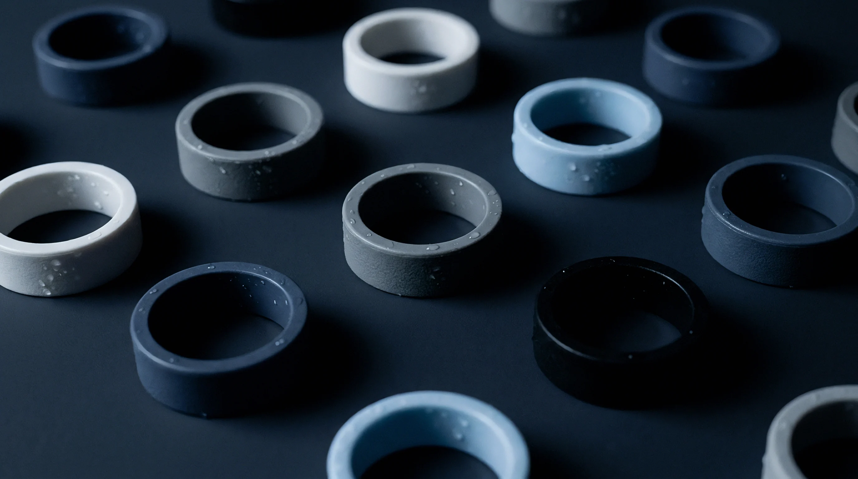
Texture Generation Methods and Surface Geometry Effects
Manufacturing methods used to produce cavity textures create distinct surface topographies that alter thermal contact resistance behavior.
| Tool Material Alloy | Thermal Conductivity (W/m·K) | Standard Hardness (HRC) | Acid Etching Performance | Laser Ablation Suitability |
|---|---|---|---|---|
| P20 (1.2311) | 29.0 | 30 – 34 | Standard | Moderate |
| H13 (1.2344 ESR) | 24.5 | 48 – 52 | Excellent | High |
| 420 Stainless (1.2083) | 19.0 | 48 – 52 | Good | Moderate |
| Ampcoloy 940 (CuNiSi) | 106.0 | 28 – 32 | Not Applicable | Low |
| Tool Steel 1.2709 (3D Printed) | 20.0 | 38 – 54 | Moderate | High |
Chemical acid etching relies on masked acid baths to dissolve localized steel pockets, creating rounded micro-valleys and smooth micro-peaks. Rounded valley profiles facilitate polymer melt entry under moderate holding pressure, minimizing trapped air volume. Electrical Discharge Machining (EDM) generates cratered, random surface topographies with sharp, brittle re-cast white layers.
These craters create micro-overhangs that trap cavity gas, yielding high initial contact resistance values that persist throughout packing.
Femtosecond laser texturing carves precise 3D surface geometries with digital control over draft angles, depth profiles, and micro-groove aspect ratios. Laser ablation eliminates chemical bath variability and recast white layers entirely. Digital texture design allows engineers to incorporate subtle draft angles into individual micro-grain sidewalls.
These micro-drafted geometries allow expanding air to escape sideways as the melt advances into micro-valleys, dramatically reducing trapped void volume and lowering thermal contact resistance.

Conformal Cooling Layouts for Textured Tooling
Conventional drilled cooling lines struggle to deliver uniform heat removal behind complex, curved textured show surfaces. Straight gun-drilled channels vary in distance from the cavity surface, creating alternating hot and cold steel regions across the part face. This variable distance compounds contact resistance differences, generating severe local thermal gradients and part warpage.
Direct metal laser sintering (DMLS) 3D printing technology enables conformal cooling channels that closely mirror complex cavity contours.
Conformal cooling channels positioned at a uniform distance (typically 1.5 to 2.0 times channel diameter) beneath textured cavity faces establish equalized thermal resistance paths across the entire tool. Conformal circuits maintain consistent steel backing temperatures, accelerating heat extraction from micro-valley air gaps. This layout minimizes internal steel thermal path resistance, counteracting boundary contact delays on deep leather-grain or geometric laser textures.
Executing high-performance textured tooling requires verifying material, geometry, and cooling specifications early in design.
- Tool steel grade verification establishes that cavity steel exhibits vacuum-degassed ESR quality to ensure uniform chemical graining and predictable micro-asperity thermal contact.
- Thermal conductivity mapping balances copper alloy insert placement behind deep textured show surfaces against high-wear steel inserts in structural parting zones.
- Laser texture draft optimization applies minimum 1.5-degree micro-draft angles to individual micro-grain sidewalls to promote micro-air evacuation during packing.
- Conformal circuit distance profiling holds additive cooling channels at a constant offset depth relative to textured geometry contours.
- Surface hardening treatment cross-check verifies that nitriding or PVD coatings do not fill fine micro-valleys or alter surface energy wetting angles.
Tooling acceptance specifications under DIN 16742 Grade TG4 specify that wall thickness shrink variations caused by textured thermal delay fall within the dimensional tolerance band of the untextured CAD baseline.
Tooling purchase agreements implementing DIN 16742 tolerance classes explicitly obligate the toolmaker to adjust cavity steel dimensions to compensate for textured thermal contraction offsets prior to final sign-off.

Valuation
Cycle Time Penalties and Machinery Operating Rates
Interfacial thermal resistance on textured mold surfaces translates directly into cycle time penalties during mass production. Slower heat dissipation through textured cavity faces extends the cooling time required for polymer walls to reach ejectable structural rigidity. An extra 1.5 to 4.0 seconds of cooling time per cycle on high-tonnage automotive or housing tools significantly impacts plant productivity and unit economics.
Machine-hour operating costs scale directly with clamp tonnage and energy consumption. Operating a 650-ton electric injection molding press carries hourly cost allocations between $75 and $130 depending on facility overhead and location. Adding 2.5 seconds to a 25-second baseline cycle time represents a 10 percent reduction in hourly part output.
Over an annual run of 500,000 components, a 2.5-second contact resistance penalty consumes 34.7 additional machine operating hours, raising conversion costs by several thousand dollars per tool cavity.
| Parameter / Financial Metric | Polished Baseline (SPI A2) | Fine Texture (VDI 18) | Coarse Texture (VDI 33) | Deep Leather Grain (MT 11010) |
|---|---|---|---|---|
| Interfacial Heat Transfer (W/m²K) | 3600 | 2800 | 1600 | 1100 |
| Required Cooling Duration (s) | 12.0 | 13.2 | 14.8 | 16.5 |
| Total Cycle Time (s) | 22.0 | 23.2 | 24.8 | 26.5 |
| Parts Per Hour (Single Cavity) | 163.6 | 155.1 | 145.1 | 135.8 |
| Conversion Cost Per 100k Parts ($) | $58,068 | $61,250 | $65,472 | $69,955 |
| Unit Cost Penalty vs Baseline ($) | $0.000 | $0.032 | $0.074 | $0.119 |
Steel selection commits capital early. Quote calculations account for two additional seconds of cooling time per millimeter of wall thickness on heavily grained show parts. Higher upfront investment in high-conductivity copper alloys or conformal 3D printed steel inserts amortizes rapidly against cycle time reductions on production runs exceeding 100,000 units.
Scrap Rates, Dimensional Yield, and Quality Audits
Thermal contact resistance variations cause intermittent scrap spikes during cold startups or thermal drift across shift changes. Startup shots on cold tools run at lower mold wall temperatures, increasing initial melt viscosity and trapping maximum air gap volumes behind textures. This higher initial resistance causes incomplete grain replication and gloss deviations on first-article parts.
Reaching steady-state thermal equilibrium requires 15 to 30 production cycles, during which parts must be segregated and audited for dimensional bow and gloss compliance.
Quality control audits measure dimensional yields using automated coordinate measuring machines (CMM) and multi-angle optical gloss meters. Asymmetric bowing caused by differential textured cooling accounts for a significant share of rejected enclosures. Implementing strict cavity wall temperature monitoring reduces scrap by ensuring hold pressure consistently overcomes micro-air gap thresholds on every cycle, maintaining stable heat transfer rates across multi-cavity tools.
Tooling Ownership and Maintenance Mechanics
Maintenance practices directly affect long-term thermal contact behavior on textured molds. Outgassing from processing polymers deposits volatile waxes and flame retardant residues within fine texture micro-valleys over extended production runs. This contamination fills air gaps with low-conductivity organic residue, permanently elevating contact resistance and degrading surface gloss fidelity.
Ultrasonic cavity cleaning and solvent degreasing protocols should be scheduled every 50,000 shots to strip micro-deposits and restore baseline heat transfer performance.
Abrasive wear from glass-filled resins gradually rounds off sharp micro-asperity peaks, reducing micro-grain height and altering surface area over time. Peak rounding increases solid contact area under hold pressure, paradoxically lowering thermal contact resistance while destroying visual texture definition. Tooling transfer contracts must define ownership responsibilities for periodic cavity re-etching, establishing clear quality thresholds where thermal performance and aesthetic grain fidelity must be restored to original CAD baselines before final sign-off and asset transfer.