Thermoforming against Injection for Volumes below Fifty Thousand Units
Thermoforming delivers lower total landed cost below fifteen thousand units by saving upfront tooling capital, beyond which injection piece price efficiency dominates.
Sheet
Heavy-gauge vacuum forming shapes extruded thermoplastic sheet into finished enclosures at a fraction of the tooling capital required for high-pressure injection molds. The process relies on rubbery-state deformation above the polymer’s glass transition temperature or melting point, where atmospheric differential or modest pneumatic assist pulls a clamped sheet over or into a milled tool. Injection molding, by contrast, forces molten resin through runners under hydraulic pressures exceeding one thousand bar, packing a closed cavity before cooling.
This distinction in melt rheology defines the structural and geometric limits of parts produced below fifty thousand units.
Extruded sheet carries an orientation and stress history from the mill. Screw shear and roll stacks align polymer chains along the machine direction, introducing directional splits in tensile modulus and impact performance. When that sheet heats up prior to forming, sag tracks molecular weight distribution and thermal conductivity.
Semi-crystalline resins like polypropylene have narrow processing windows because their melting transitions are sharp, while amorphous plastics like acrylonitrile butadiene styrene and polycarbonate soften gradually and tolerate web temperature variation. As internal stresses relax under heat, the sheet shrinks inside the clamp frame before ever touching the mold.
Injection molding erases that upstream thermal history in the barrel. High shear through the nozzle and gate uncoils polymer chains, dropping viscous resistance as resin enters the cavity. Once material hits cold steel, a frozen skin forms instantly against the wall while the core remains molten, producing a distinct skin-core morphology.
Molecular orientation peaks directly behind the advancing freeze front, locking aligned chains into the exterior while the center cools slowly and isotropically. That cross-sectional gradient largely governs part warpage, anisotropic shrinkage, and load-bearing behavior.
Wall Thickness Distribution and Stretch Dynamics
In vacuum and pressure forming, final wall thickness depends on how far the sheet stretches before freezing against mold steel. Straight drape forming over a male core thins the perimeter base while leaving the apex near original gauge. Female cavities do the opposite: the rim stays heavy and the deep-drawn bottom thins out.
Toolmakers counter severe localized thinning with plug assists, pushing warm plastic deep into the cavity with syntactic foam or aluminum plungers before pulling vacuum. Plug geometry, penetration speed, and stroke timing dictate where resin lands, keeping corners from starving out.
Injection tooling delivers uniform nominal walls across complex shapes because pressurized liquid melt follows the paths of least fluid resistance. Ribs, bosses, and wall intersections still require careful proportioning against the nominal wall to avoid cosmetic sink marks on the show surface. Thickness transitions above twenty percent risk flow hesitation, trapped gas, and uneven volumetric shrink.
Where injection designs rely on constant wall sections for stiffness, thermoformed parts inevitably carry variable wall profiles that demand conservative structural assumptions.
| Process Characteristic | Heavy-Gauge Thermoforming | High-Pressure Injection |
|---|---|---|
Draw ratio calculations dictate whether a deep enclosure is feasible in thermoforming. The ratio of finished part surface area to the original clamped footprint governs net thinning: a three-to-one draw thins a six-millimeter sheet down to an average of two millimeters, with deep corners dipping below one millimeter if plug timing drifts. Corner radii have to open up as draw depth increases to keep corners from blowing out.
Injection molding avoids draw ratios entirely, working instead within flow-length-to-thickness limits set by resin melt viscosity.
Polymer Morphology and Stress Distribution
Cooling dynamics differ fundamentally between open-surface pneumatic forming and closed-cavity molding. A thermoformed part sheds heat primarily through the tool face it contacts; the back side cools into ambient plant air or under fan banks. This single-sided contact builds an asymmetric thermal gradient through the thickness.
The tool-contact skin freezes fast, locking in its microstructure, while the free side cools slowly and continues relaxing stresses. That thermal imbalance induces post-mold bowing, often requiring dedicated cooling fixtures to hold flat panels true after demolding.
Single-sided cooling on three-millimeter amorphous sheet induces up to zero point four percent directional bow when core-to-surface delta exceeds fifteen degrees Celsius.
Injection molds pull heat symmetrically from both sides through cooling lines drilled into the core and cavity blocks. Steel tooling circuits balance heat extraction from the part centerline outward, minimizing residual bending moments across broad, flat areas. Technicians can also bias cooling line temperatures between mold halves intentionally to counteract geometry-induced warpage and dial in final part flatness.
Residual stress dictates how well a finished part resists environmental stress cracking over its service life. Thermoformed parts retain substantial orientation stress in sections formed near the bottom of their processing window, which can trigger craze growth and cracking around aggressive chemicals. In injection molded parts, residual stress concentrates around gates where packing pressure packs extra material into freezing channels.
Annealing relieves built-in orientation in critical components, but it adds cycle time, fixturing, and unit cost.
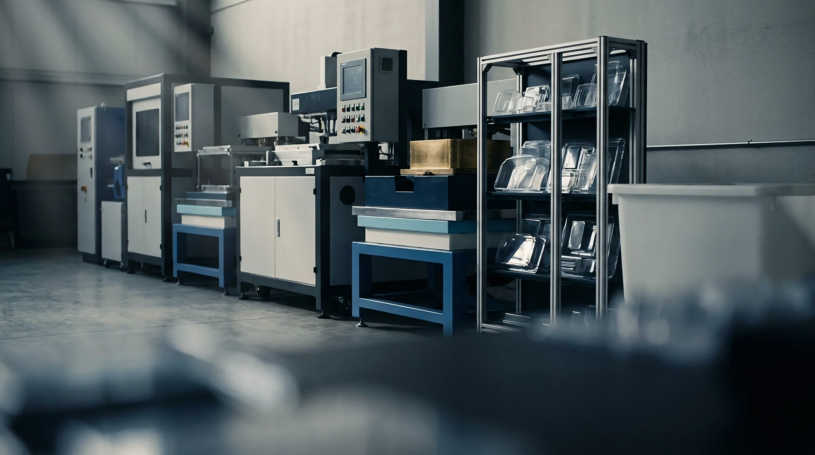
Draft Angles and Feature Definition
Part shrinkage dictates minimum draft angles for both processes. On male thermoforming cores, cooling plastic shrinks tightly onto the tool. Draft angles below three degrees risk scuffing, galling, or part distortion during air ejection.
Female cavities benefit from this shrinkage: as the plastic cools, it pulls inward and away from cavity walls, making draft angles as shallow as one degree workable without scuffing textured faces.
Internal structural features highlight the tooling divide between the two methods. Injection molds form crisp internal corners, fine surface textures, stiffening ribs, alignment bosses, and thread details directly in the steel. A thermoformed part captures sharp detail only on the side contacting the mold; the non-tool surface softens every transition and washes out fine features.
Reinforcements like snap fits and tall mounting bosses cannot be pulled directly from heavy-gauge sheet and must be added later as secondary injection-molded components using adhesive or ultrasonic welding.
Adding internal rib structures to thermoformed covers doubled secondary assembly labor in tooling evaluations where internal gridwork could not be drawn into the primary sheet without leaving sink marks on the show face. Injection tooling absorbs that structural detail directly into core steel, eliminating downstream bonding steps at the expense of upfront mold cost.
Undercuts add mechanical complexity in either process. Injection molds use angle pins, hydraulic core pulls, collapsing cores, or lifters to clear trapped geometry during mold opening. Thermoforming tools rely on articulated core sections, air-actuated side slides, or loose aluminum pick-outs that eject with the part and get stripped by hand.
Loose inserts slow cycle times and add labor, making them practical only for small runs where automated side actions would not pay for themselves.
- Web Bridging Failure occurs when warm sheet bunches across narrow internal channels, creating unintended webbing between adjacent male mold projections.
- Corner Thinning Strain arises from excessive localized draw ratios, driving wall dimensions below structural design tolerances under mechanical load.
- Chill Mark Bands form when cold plug-assist materials contact warm sheet prematurely, locking in thickness lines across cosmetic surface zones.
- Blistering Distortions develop when absorbed atmospheric moisture vaporizes inside hygroscopic polymers like polycarbonate during radiant heating cycles.
Parting lines highlight another clear workflow difference. Injection tools shut off on precision-ground steel faces, trimming the part edge in the mold and preventing flash under clamp tonnage. Thermoforming tools do not separate the part from the sheet during forming; the part emerges attached to a clamped scrap skeleton.
Establishing finished boundaries requires a secondary trimming pass, shifting final dimensional control from the mold maker to five-axis CNC router fixtures.
A rule of thumb dictates that female thermoforming cavities yield tighter outer dimensional consistency while male cores yield precise internal pocket dimensions.

Steel
Aluminum dominates low-volume thermoforming tooling because it cuts quickly and conducts heat efficiently. Cast tooling plate like Mic6 and forged alloys like 7075-T6 machine fast on high-speed CNC mills, holding toolroom labor well below steel benchmarks. Aluminum’s thermal conductivity is roughly four times that of P20 mold steel, providing rapid heat extraction through the tool face even with straightforward water line layouts.
For runs below fifty thousand parts, aluminum tools resist surface wear and handle vacuum-forming clamping pressures without issue.
Injection tooling for runs under fifty thousand parts typically uses pre-hardened P20, NAK80, or 7075-T6 aluminum inserts mounted in standard steel mold bases. Injection pressures, gate erosion, and repeated clamp cycles subject tooling to mechanical fatigue that quickly damages softer metals. Aluminum injection molds can cut build times by thirty percent and reduce initial mold costs, but they require strict process control to prevent parting line peening, flash, or stripped hydraulic ports.

Machining Operations and Vacuum Plumbing
Forming pressure in vacuum operations peaks at one atmosphere, or roughly six atmospheres when using pressure-assist air boxes. These low operating pressures allow lighter mold wall sections and simplified clamping frames. Vacuum evacuation requires micro-holes drilled through the tool cavity to vent air trapped behind the sheet.
Drill diameters must stay below zero point eight millimeters; anything larger lets hot plastic draw into the vent holes, leaving visible cosmetic witness marks on the part surface.
Deep pockets and tight internal radii often use porous aluminum inserts or wire-EDMed perimeter vent slots instead of drilled holes. Porous inserts pull vacuum uniformly across textured faces without individual vent marks. Injection molds vent through ejector pin clearances and shallow parting line reliefs.
Because molten polymer has high viscosity, air escapes through gaps under zero point two millimeters without the plastic flashing into the vents.
Cooling lines in thermoforming tools are gun-drilled or cast directly into the aluminum as copper tubing. Mold temperatures run between thirty and seventy degrees Celsius to balance sheet cooling against overall cycle time. Uniform thermal distribution across the tool face is critical to avoid differential shrinkage over long spans.
Injection molds require much more aggressive, tightly controlled cooling loops ~ often conformal or cross-drilled ~ to handle melt entering at up to three hundred degrees Celsius.
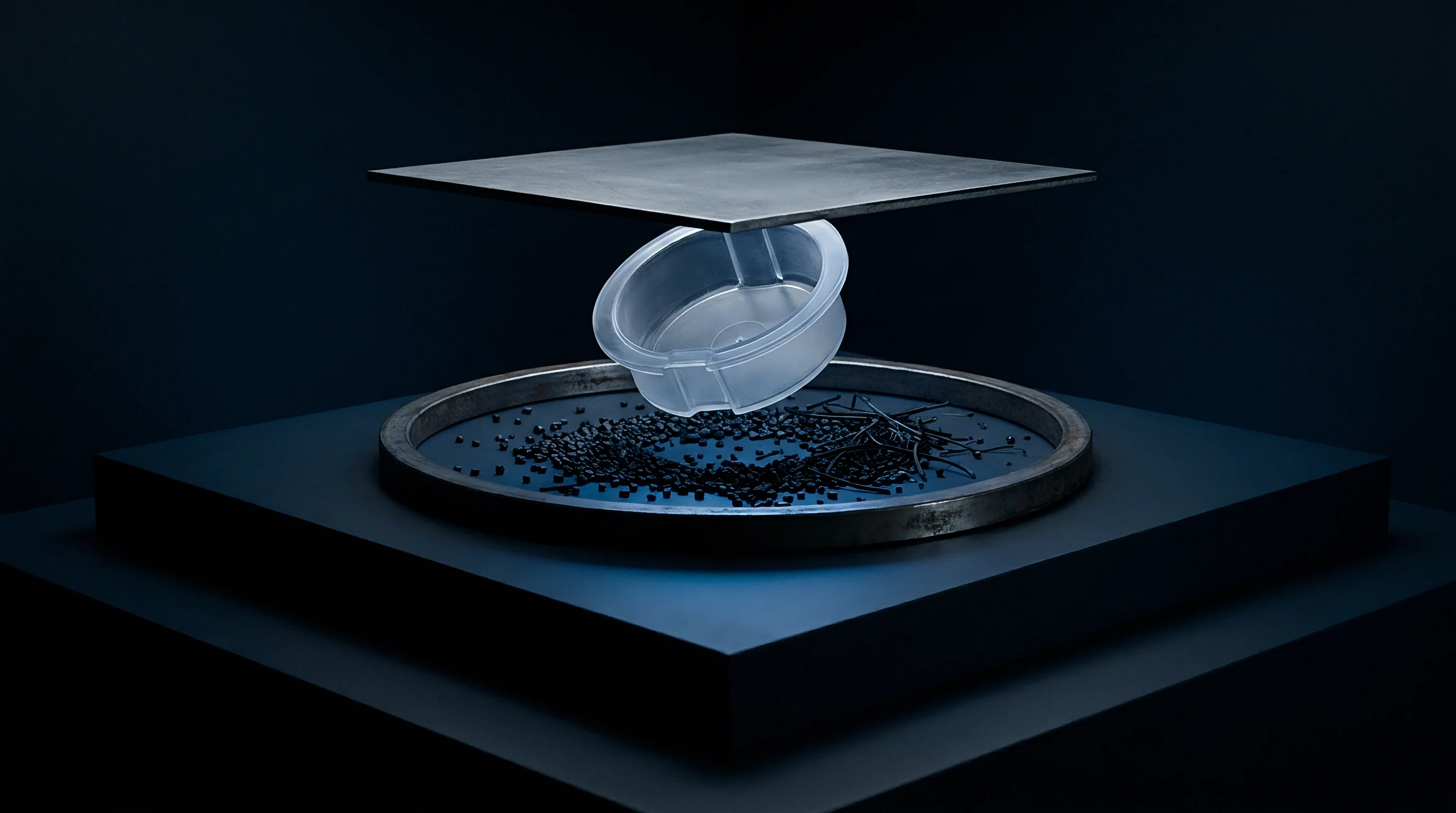
Injection Tooling Complexity and Cavitation
Injection presses need heavy, rigid steel plates to handle hundreds of tons of clamp force without deflecting. A single-cavity mold for a mid-sized trim panel includes core and cavity blocks, ejector pins, guided ejector plates, sprue bushings, hot or cold runner manifolds, and leader pins. That steel requirement drives up material and machining costs long before the mold touches a press.
Adding cavities multiplies the initial tooling bill, which makes multi-cavity injection molds hard to justify for short production runs.
Hot runner systems eliminate runner scrap and reduce cycle times by keeping plastic molten right up to the cavity gate. However, the manifold and its temperature controllers can cost more than an entire thermoforming tool. Short runs rarely justify hot runners, forcing molders toward cold runner layouts that add sprue weight to every shot, consume more material, and require press-side regrind operations.
- Mount the machined mold onto the thermoforming platen, verifying surface flatness across mounting interfaces using dial indicators.
- Connect vacuum lines, pressure assist lines, and fluid temperature control circuits, confirming pressure tight seals under operational limits.
- Cycle radiant heater banks over an unformed sheet test sample, measuring temperature distribution across nine web grid points using calibrated infrared sensors.
- Initiate automated forming sequence, adjusting plug assist depth and vacuum actuation timing to eliminate localized web drag lines.
- Extract first article parts after cool-down, subjecting profiles to coordinate measuring machine dimensional layout against master computer aided design models.
Side actions in injection tooling allow complex geometry but drive up tool costs quickly. Hydraulic cylinders, horn pins, and sliding cores require careful hand-fitting and hardening to prevent galling during production. Thermoforming tools handle minor undercuts with simpler mechanisms: air-actuated mechanical flips, hand-loaded inserts, or segmented cores that collapse as the part lifts.
Keeping moving mechanisms out of the main tool keeps upfront costs down on low-volume projects.
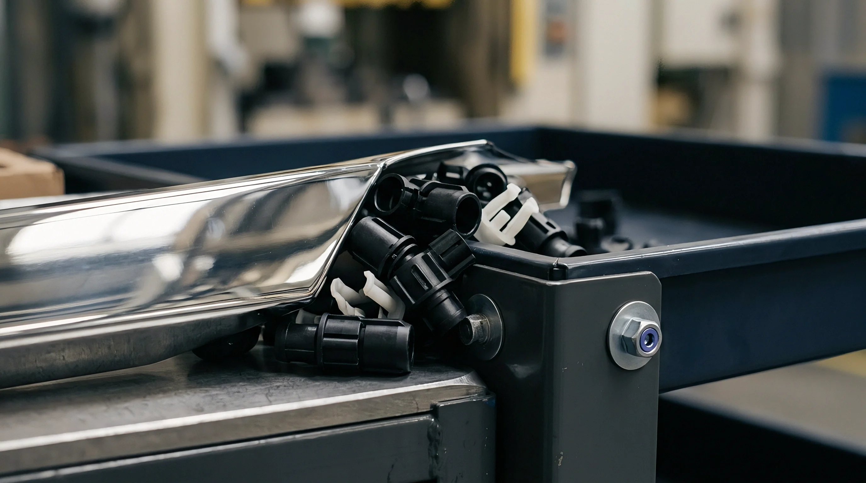
Secondary Operations and Machining Fixtures
Edge trimming creates a sharp divide between thermoforming and injection molding workflows. Injection tools kick out finished parts at the press, needing only a quick gate de-vesting step. Thermoforming leaves the formed part surrounded by a flat flange clamped during the cycle.
Removing that excess material requires dedicated five-axis CNC router fixtures or trim dies, and that secondary tooling must be factored into project startup costs.
Incorporating dedicated five-axis vacuum routing fixtures adds four thousand to twelve thousand dollars in secondary tooling capital per component geometry.
Router fixtures use cast aluminum or high-density tooling board shaped directly to the part geometry. Embedded vacuum channels pull the flexible shell down tight against the fixture to resist side loads from high-speed spindles. Routing bits spinning at twenty thousand revolutions per minute trim perimeter flash and cut out internal windows, holes, and mounting slots.
Fixture rigidity dictates hole-to-hole accuracy: if vacuum drops, the shell flexes and cut features wander off location.
Higher-volume thermoforming operations use steel rule or matched punch dies to blank parts out in a single press stroke. Matched blanking dies need hardened steel edges, die sets, and heavy mechanical or hydraulic trim presses. Tooling costs for matched punch dies approach those of short-run injection molds, limiting their use to programs where CNC router cycle times bottleneck the shop.
Finishing aluminum thermoforming tools involves bead blasting, chemical texturing, or hand polishing to set the final part appearance. Plastic sheet picks up tool face flaws cleanly, so a scratch on an aluminum core will transfer to the inside of every part. Injection mold faces receive diamond-buffed polishes, standard SPI finishes, or chemical textures, often protected with hard chrome or nitriding to resist wear from glass-filled resins over hundreds of thousands of shots.
Parting line flash after ten thousand cycles is often blamed on aluminum wear when the real culprit is excessive or uneven clamp pressure crushing the tool face.

Drift
Dimensional repeatability in thermoforming comes down to sheet gauge consistency, oven cycle control, and shop environment stability. Extruded sheet typically carries a thickness tolerance of plus or minus five percent. A five-millimeter sheet on the heavy side holds more thermal mass and takes longer to reach forming temperature.
Running varying sheet thickness on a fixed oven timer leads to shifting sheet temperatures, inconsistent stretch, uneven wall thinning, and dimensional drift between lots.
Injection molding provides better lot-to-lot consistency because modern electric presses run closed-loop control over shot volume, injection speed, and pack pressures. Presses control screw position to within hundredths of a millimeter, holding consistent cushions and transfer points. Virgin resin pellets from consistent lots maintain uniform melt flow rates, letting technicians establish stable process windows where volumetric shrinkage stays predictable across thousands of cycles.
Dimensional Stability and Shrinkage Stack
Shrinkage calculations for thermoforming have to account for both thermal contraction and the recovery of extrusion stresses. Polymer chains oriented during sheet extrusion relax under radiant heat, shrinking along the machine direction before the sheet ever hits the mold. After forming, the plastic shrinks onto male cores or away from female cavity walls until demolding.
Unconstrained flat sections continue shrinking at room temperature for up to forty-eight hours, so measuring parts immediately off the press can give misleading quality data.
Injection mold shrink calculations use standard shrink rates supplied by resin vendors, adjusted for gate location, nominal wall thickness, and cavity pressure. Linear shrinkage in semi-crystalline resins like high-density polyethylene can hit two percent, with marked differences parallel and perpendicular to flow. Amorphous materials like ABS shrink far less ~ around zero point five percent ~ and behave isotropically, making dimensions easier to hold across long spans without repeated tool recuts.
| Tolerance Parameter | Standard Injection (TG5) | Precision Injection (TG3) | Heavy Thermoforming (TG7) |
|---|---|---|---|
Tolerance standards like DIN 16742 place thermoforming in looser categories than injection molding. Thermoformed parts usually fall into Tolerance Grade TG7 or TG8 because of single-sided tool contact and routing fixture variations. Injection molded components routinely meet TG4 or TG5, and well-tuned precision tooling can reach TG3 on critical mating features.
Trying to hold injection-grade tolerances on thermoformed parts drives scrap rates and inspection overhead up fast.
When Does Trimming Accuracy Compromise Mating Tolerance?
Secondary trimming is the main source of variation in thermoformed assemblies. While mold-side features reflect CNC tool precision, perimeter cut lines, routed cutouts, and latching details depend on five-axis router calibration and part hold-down. If vacuum hold-down pressure drops, the shell flexes under tool engagement loads, causing cut paths to drift from nominal coordinates.
Hole-to-hole distances cut in a single router setup hold tight positional tolerances. The real difficulty lies in locating routed holes relative to molded features on the shell. Part expansion between press ejection and trimming changes how the part sits in the nest.
A ten-degree Celsius shift in factory ambient temperature can expand a one-meter polypropylene or polyethylene cover by over one millimeter, enough to fail CMM inspection on mounting hole locations.
Injection molds form holes, cutouts, and perimeter edges directly in the steel cavity, eliminating secondary trimming error. Hole locations relative to walls and bosses stay repeatable over thousands of shots, determined entirely by cavity geometry and uniform material shrink. For assemblies requiring tight perimeter gaskets, snap fits, or rigid PCB mounting posts, injection molding remains the standard approach because all critical features freeze in place simultaneously.
Applying a thermal expansion allowance clause under ISO 20753 prevents lot rejection when measuring flexible polyolefin components across seasonal ambient factory shifts.
Perimeter edge drift reached zero point eight millimeters across thermoformed enclosures run on separate shifts under varying ambient conditions. The day run operated at twenty-two degrees while the night shift dropped to twelve degrees. Because heating cycles ran on fixed timers, the colder night sheet never reached full forming temperature, shrinking inconsistently during cool-down and pulling routed hole centers out of drawing tolerance.

Thermal Variations across Web and Cavity
Thermoforming oven banks rely on ceramic, quartz, or halogen heating elements arranged in grid zones. Output drifts over time as elements age or change resistance. Heat also spills off the outer edges of the clamping frame, leaving sheet perimeters cooler than the center.
Without closed-loop pyrometers and active zone control, temperatures across the sheet can swing by twenty degrees Celsius, altering stretch dynamics and resulting wall thickness.
- Radiant Heater Bank Drift shifts local sheet temperatures, generating non-uniform wall stretch and unexpected dimensional variance across production batches.
- Secondary Routing Deflection occurs when spindle cutter force pushes unsupported plastic wall sections away from intended toolpaths.
- Hygroscopic Expansion alters dimensions of finished nylon and polycarbonate parts as they absorb ambient humidity post-processing.
- Fixture Wear Slop develops in secondary machining nests, introducing positioning offsets between molded features and routed holes.
Injection mold cooling keeps core and cavity temperatures stable through fast cycles. Temperature control units circulate water or oil at high flow rates to maintain turbulent flow and maximize heat transfer. In-cavity pressure transducers monitor the melt in real time, allowing press controllers to adjust pack and hold pressure dynamically if melt viscosity drifts between material lots.
Medical and industrial component qualification usually demands documented capability indices. Holding a Cpk above one point three three on critical dimensions requires tight process windows. Injection molding achieves those numbers reliably on complex geometry through scientific molding practices.
Thermoforming generally requires broader drawing tolerances or secondary machining operations to deliver comparable statistical capability on mating features.
An open question remains whether low-cost optical 3D scanning systems can provide real-time feedforward offset coordinates to five-axis router controllers to dynamically compensate for part-to-part thermal expansion shifts during short-run trimming operations.


Ledger
Tooling cost is usually the initial hurdle when launching a plastic enclosure. An aluminum thermoforming mold for a medium-sized housing runs between eight thousand and twenty-five thousand dollars, depending on geometry, plug assists, and CNC trimming nests. An injection mold for that same housing typically costs forty thousand to one hundred twenty thousand dollars in single-cavity P20 steel, climbing further if hot runners or side-action lifters are needed.
Piece price flips that dynamic. Injection molding uses raw resin pellets purchased in bulk, carrying little processing markup. Thermoforming runs on pre-extruded sheet that carries a thirty to sixty percent cost premium over raw resin to cover extrusion, handling, and logistics.
On large parts with heavy walls, that sheet premium accumulates quickly and steadily eats away at the initial tooling savings.
Tooling Capital Amortization Mechanics
Amortizing tooling across the production run shows the exact crossover point between the two methods. Dividing tooling cost by total volume and adding the piece price gives the landed unit cost. At five hundred parts, a thirty-thousand-dollar injection mold adds sixty dollars of tooling burden to every piece.
An eight-thousand-dollar thermoforming tool adds sixteen dollars per part at that volume, giving thermoforming an overwhelming cost advantage for short production runs.
Higher volumes erode that tooling difference. At twenty-five thousand units, the injection tool burden drops to one dollar and twenty cents per piece, while thermoforming tooling sits at thirty-two cents. By then, injection molding’s lower piece price ~ driven by faster cycles and raw pellet pricing ~ more than offsets the remaining eighty-eight-cent tooling gap.
Total landed cost lines cross, and injection molding becomes the cheaper route from that point forward.
| Volume Tier (Units) | Thermoform Tool Amort. | Thermoform Piece Price | Injection Tool Amort. | Injection Piece Price | Landed Cost Advantage |
|---|---|---|---|---|---|
Cycle times drive press hourly cost allocations. Injection presses run fast, producing a typical enclosure in thirty to forty-five seconds. Automated robotics demold parts, trim sprues, and pack boxes with minimal operator involvement.
Machine rates for mid-sized injection presses run between sixty and ninety dollars per hour, spreading overhead efficiently across large production lots.
Heavy-gauge thermoforming cycles run much longer ~ usually ninety to one hundred eighty seconds. Heating thick sheet takes time, creating an oven bottleneck that cannot be rushed without burning the plastic surface. Secondary CNC trimming adds another two to four minutes of router time per shell.
Paying for both forming and routing time, alongside manual sheet handling, results in higher per-unit machine and labor costs.

Resin Pricing Disparities and Scrap Factors
Scrap generation further penalizes thermoforming economics. Clamped perimeter sheet outside the mold edge cannot be formed into parts and becomes skeleton scrap. On complex layouts, skeleton scrap accounts for thirty to fifty percent of total sheet weight.
While that scrap can be ground and re-extruded, virgin-to-regrind limits restrict how much regrind can go back into structural sheet without degrading properties, leaving molders with unrecovered conversion costs.
Injection molding material efficiency approaches ninety-eight percent with hot runner systems, as molten plastic feeds directly into cavity gates without web scrap. Cold runner molds generate runner sprues, but runner mass is small compared to part weight on larger parts. Press-side grinders chop cold runners immediately for controlled re-introduction into the hopper, keeping resin waste low.
- Extruded Sheet Premium Clause establishes baseline resin costs tied to published sheet market indexes rather than raw pellet market spot prices.
- Minimum Order Quantity Surcharge applies when custom sheet colors or non-standard gauge widths require custom extruder setup runs.
- Secondary Routing Overhead allocates machine spindle time, cutter wear, and hold-down vacuum fixture maintenance into component unit pricing.
- Tool Maintenance Allocation sets responsibilities for aluminum mold surface repolishing and pneumatic seal replacement over multi-year production contracts.
Polymer grade selection widens this cost spread. Commodity resins like ABS and high-impact polystyrene carry manageable extrusion markups over base pellets. High-performance polymers like polyetherimide, polyetheretherketone, or flame-retardant polycarbonate-ABS blends carry steep extrusion premiums.
Specifying engineering resins in thermoforming multiplies the cost of skeleton scrap, pulling the economic crossover point toward injection molding at lower production volumes.
Engineering revisions during production carry very different price tags in each process. Modifying an aluminum thermoforming mold involves minor CNC recuts or welding, typically running hundreds to a few thousand dollars. Modifying hardened injection steel requires EDM sinking, welded inserts, or precision rebuilds that can quickly exhaust project contingency budgets.
Altering mounting hole locations on a low-volume medical housing incurred a six-thousand-dollar tooling rework fee simply because moving the pattern meant rebuilding the secondary five-axis CNC vacuum routing fixture from scratch.