Modifying Nominal Wall Sections during Injection Moulding Tooling Qualifications
Modifying nominal wall sections during tooling qualification requires balancing flow pressure drops against cooling cycle delays and steel-safe machining routes.


Core
First shots off a new injection moulding tool rarely match the 3D CAD model perfectly. Adjusting nominal wall thickness during qualification is usually the primary way engineers fix cosmetic sink, flex, flow hesitation, short shots, and high injection pressures. The work follows two basic paths: steel-safe changes, where metal is cut from core or cavity surfaces to thicken a wall, and non-steel-safe changes, where metal has to be added back ~ using laser welding, wire EDM inserts, or a new core ~ to thin it down.
Changing a wall section alters the cross-sectional area open to polymer flow, shifting flow rates, runner-to-cavity pressure drops, and cooling behavior all at once.
Thickening a wall cuts flow resistance sharply because pressure drop through a rectangular channel scales with the inverse cube of wall thickness in laminar polymer flow. Thinning it does the opposite ~ it spikes flow resistance, raises melt shear rates, and can extend cooling cycles if uneven shrinkage warps the part. Qualification protocols dictate whether geometry changes can be tucked away on non-functional internal ribs or must land on cosmetic class-A exterior surfaces.
Either way, changing wall thickness alters the part’s overall thermal mass, shifting cycle times and internal stress distribution. Before cutting steel, engineers have to make sure fixing a local cosmetic defect won’t cause dimensional drift on mating features elsewhere.

Triggers for In-Qualification Wall Section Adjustments
During T1 sampling, tooling engineers and setters look for specific physical signs that point to nominal wall changes:
- Cosmetic sink marks forming opposite structural ribs, bosses, or thick gussets, where local volumetric shrinkage pulls the frozen skin inward during cooling.
- Unbalanced flow fronts across multi-cavity tools or wide surfaces that lead to premature gate seal, excessive shear heating, or structural weld lines in load paths.
- Short shots caused by high pressure drops along long flow-length-to-thickness pathways that exceed press pressure limits.
- Part warpage driven by uneven cooling between thick nominal surfaces and adjacent thin ribs, creating internal bending moments upon ejection.
- Structural flexure during load testing when off-tool stiffness misses compliance targets because of uncalculated material anisotropy.
Engineers evaluate these defects using short-shot series and cutaways of first-article samples. Checking profiles with ultrasonic thickness gauges frequently reveals localized thinning caused by thin core pins deflecting under injection pressure. That pin flex distorts channel symmetry, yielding uneven wall sections that compound cooling imbalances across opposite sides of the moulding.
Rule of thumb: Steel removal increases local wall section thickness and decreases melt pressure drop without requiring higher barrel temperatures or longer injection time.
If core shift occurs during filling, adjusting tool steel to offset pin deflection keeps wall thickness consistent across injection speeds. Engineers check if the tool layout permits core support changes before removing metal from cavity walls. Modifying the core side leaves cosmetic class-A exteriors untouched and maintains the outer envelope dimensions needed for mating housings.

Steel-Safe versus Steel-Unsafe Execution Routes
Before modifying wall thickness during qualification, proposed geometry changes are classified by machining feasibility and risk. Steel-safe changes cut metal away from core or cavity blocks using five-axis CNC milling, sinker EDM, or precision grinding. Opening up cavity volume yields a thicker wall.
Removing steel is straightforward and protects tool integrity without introducing heat-affected stress zones.
Non-steel-safe modifications thin a wall by adding metal back into the cavity or core. This requires micro-laser welding with matching filler wire, machining pocket recesses for ground insert blocks, or building new core inserts altogether. Laser cladding deposits metal layers that are ground back to size, but welding risks heat-affected zone cracking and hardness swings across polished surfaces.
Swapping in a fresh core avoids metallurgical defects entirely, though it drives up cost and adds lead time to the qualification schedule.
Removing core steel takes roughly eighteen hours, whereas adding metal to a cavity block requires four days for wire EDM insert pocketing and fitting.


Shrink
Volumetric shrinkage dictates how wall changes affect final part dimensions. Thermoplastics contract as they cool from a molten state into semi-crystalline or amorphous structures inside the mold. Semi-crystalline polymers like polypropylene, polyamide, and polybutylene terephthalate shrink between 1.5 percent and 3.0 percent volumetrically, whereas amorphous resins like polycarbonate and ABS shrink only 0.4 percent to 0.8 percent.
Thickening a wall in a semi-crystalline part expands the molten core volume, delaying core freeze and pushing total volumetric shrinkage higher.
Cooling rates directly shape crystalline structure in semi-crystalline polymers. Thick sections cool slowly because polymer melt conducts heat poorly ~ roughly 0.15 to 0.25 W/m K. Slow cooling gives polymer chains time to arrange into dense crystalline spherulites, raising local density and linear shrink. Increasing a polypropylene housing wall from 2.0 mm to 2.5 mm, for instance, boosts local linear shrink from 1.6 percent to 2.1 percent, pulling hole-to-hole centerlines off CAD nominals and throwing off mating tolerances.

Polymer Structure and Volumetric Thermal Contraction
Unequal wall sections shift thermal gradients across the moulding, triggering uneven shrinkage between class-A and class-B surfaces. If a core-side wall is made thinner than the cavity side, the cavity face stays hot longer and pulls the part toward itself as the mold opens. Managing tool temperature requires balancing wall dimensions against local cooling channel placement and water flow rates to keep heat extraction uniform.
| Polymer Grade | Structure Class | Nominal Wall Baseline (mm) | Modified Wall Thickness (mm) | Volumetric Shrinkage (%) | Linear Shrinkage Deviation (%) | Sink Mark Sensitivity Depth (mm) |
|---|---|---|---|---|---|---|
| Polypropylene Unfilled | Semi-Crystalline | 2.0 | 2.8 | 1.85 to 2.40 | +0.45 | 0.12 |
| PA66 30% Glass Filled | Semi-Crystalline | 2.0 | 2.5 | 0.50 to 0.85 | +0.12 | 0.03 |
| ABS General Purpose | Amorphous | 2.5 | 3.2 | 0.50 to 0.70 | +0.08 | 0.04 |
| Polycarbonate Optical | Amorphous | 2.0 | 2.6 | 0.60 to 0.80 | +0.06 | 0.02 |
| PBT 15% Glass Filled | Semi-Crystalline | 1.5 | 2.2 | 0.80 to 1.30 | +0.28 | 0.07 |
| Data compiled from qualification sample measurement protocols under standard ISO 294 test conditions at 23°C and 50% RH. | ||||||
Glass-fiber reinforced thermoplastics contract anisotropically when wall thickness changes. Fibers align along the flow path during filling, suppressing shrinkage along that axis while leaving transverse shrinkage unhindered. Thickening a glass-filled wall enlarges the center core where fibers stay randomly oriented, increasing transverse shrink relative to flow-direction shrink and heightening warpage risks.

Sink Mark Depth Calculations and Rib-to-Wall Ratios
Altering wall sections changes the rib-to-wall ratios needed to prevent cosmetic surface sink. Standard practice calls for intersecting ribs to measure 40 percent to 60 percent of nominal wall thickness for unfilled resins, and up to 80 percent for fast-freezing glass-filled grades. If qualification forces a wall reduction from 3.0 mm to 2.2 mm to drop weight or cut cycle time, an unadjusted 1.8 mm rib suddenly jumps to 82 percent of the new wall thickness, leaving distinct sink marks on cosmetic faces.
Predicting sink mark depth Sd across changing wall sections relies on empirical thermal contraction modeling, tracking local volumetric shrinkage Vs, wall thickness Tw, rib thickness Tr, and hold pressure effectiveness Ph in the cavity core:
Sd = C · left( fracTrTw right)2 · Vs · left(1 – fracPhPmaxright)
Here, C is the material thermal diffusibility constant and Pmax is the maximum non-flashing hydraulic packing limit. As the Tr / Tw ratio grows from thinning a wall without adjusting the rib, sink mark depth scales quadratically. Setters often try to compensate by ramping up hold pressure or extending pack time, but high pack pressures build up residual stress near the gate, inviting environmental stress cracking later during storage or assembly.
Volumetric shrinkage scales non-linearly with wall thickness expansion in semi-crystalline resins, requiring holding pressure adjustments to prevent internal void formation.
Internal voids form when the outer skin freezes rapidly while the thick inner core keeps shrinking without receiving fresh melt through the gate. If the gate freezes before the center wall solidifies, holding pressure cannot reach the core. Ultrasonic flaw detection uncovers these micro-voids in thickened wall intersections, where they lower impact strength and lead to mechanical failure under load.
Varying shrinkage rates across non-uniform walls leave severe thermal stresses behind. Thin sections freeze fast, while neighboring thick sections stay hot and pliable. When those thick areas finally cool and contract, they pull against the rigid thin sections, locking tensile stress into internal junctions.
Over time, these locked-in stresses relax through gradual part distortion or sudden brittle failure under load.
Engineers manage shrinkage during wall adjustments by maintaining uniform taper ratios across section changes. Stepping down from a 3.0 mm wall to a 2.0 mm wall requires a continuous taper length at least three times the thickness difference to prevent stress concentrations and keep flow front behavior uniform.

Cutter
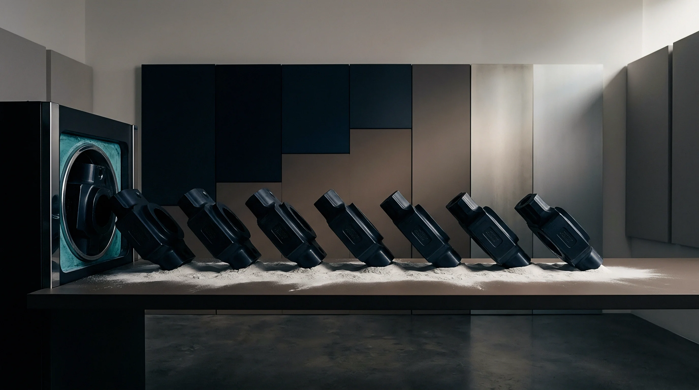
Cutting tool steel to adjust wall dimensions requires machinery capable of hitting sub-hundredth-millimeter tolerances on hardened blocks. Shops generally use pre-hardened steels like P20 (1.2311) at 30 to 32 HRC for medium-volume tooling, or fully hardened H13 (1.2344) and S7 at 48 to 54 HRC for high-volume production runs. Modifying hardened steel after T1 trials narrows machining methods down to high-speed CNC milling with carbide or cubic boron nitride tools, sinker EDM, and micro-laser cladding.
Selecting between metal removal and deposition depends on cavity access, surface finish requirements, and distance to cooling lines or ejector pins. Sinker EDM uses shaped graphite or copper-tungsten electrodes to erode tool steel without exerting cutting forces on thin or delicate features. It excels in deep slots or narrow ribs where conventional milling cutters would flex under load.
| Modification Process | Material Addition/Removal | Volumetric Rate (mm³/min) | Achievable Tolerance (mm) | Surface Finish (Ra µm) | Heat-Affected Zone Risk |
|---|---|---|---|---|---|
| High-Speed CNC Milling | Removal (Steel Safe) | 150 to 450 | ±0.008 | 0.40 to 0.80 | Negligible |
| Sinker EDM | Removal (Steel Safe) | 10 to 50 | ±0.005 | 0.80 to 3.20 | Moderate (White Layer) |
| Wire EDM Pocketing | Removal (Steel Safe) | 20 to 80 | ±0.003 | 0.20 to 0.40 | Low |
| Micro-Laser Cladding | Addition (Non-Steel Safe) | 2 to 10 | ±0.025 | 3.20 to 6.30 | High (Requires Annealing) |
| TIG Welding (Tool Grade) | Addition (Non-Steel Safe) | 15 to 40 | ±0.100 | 6.30 to 12.50 | Severe (Distortion Risk) |
Cutting steel near conformal or conventional cooling lines carries real breakout risks. Removing 0.5 mm from a core to thicken a wall reduces the steel separating the cavity surface from pressurized cooling water. Tool designers keep a minimum safety margin of 4.0 mm between coolant channels and plastic molding surfaces to avoid thermal fatigue cracking or blowout under water pressures up to 6 bar.
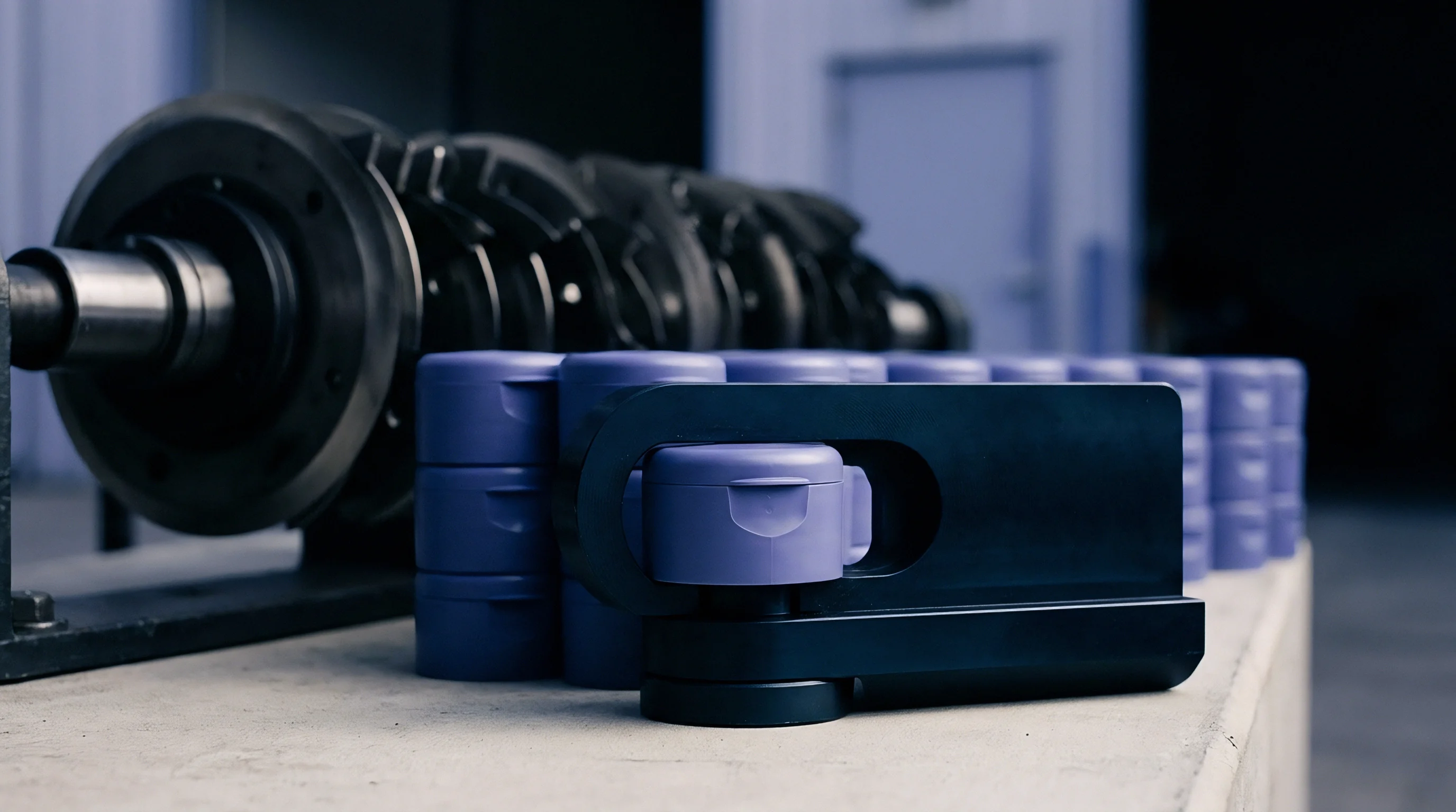
Machining Execution Steps for Core Adjustments
Executing a steel-safe core modification to increase nominal wall thickness proceeds through a sequential toolroom workflow:
- The toolroom disassembles the core side of the tool, taking out ejector pins, slide assemblies, and internal core pins.
- Machinists mount the core block on a CMM to set precise zero-point datums relative to guide pin bushings.
- CAM programmers load the updated 3D CAD model with the new wall thickness and generate toolpaths using high-speed finish passes with toroidal carbide endmills.
- A high-speed CNC mill machines the core faces under high-pressure oil coolant, leaving 0.02 mm of stock for bench polishing.
- Toolmakers stone and polish the machined surfaces back to original draw polish specs, maintaining draft angles for clean part ejection.
- Inspectors re-check core dimensions on the CMM to verify target modifications before reassembling ejector plates and water lines.
Sinker EDM relies on custom graphite electrodes shaped to match the expanded wall geometry. Electrodes are sized smaller to allow for the spark gap ~ typically 0.015 mm to 0.040 mm depending on current density and surface requirements. Spark erosion leaves a brittle, micro-cracked white layer on the steel that must be polished out or re-textured.
Leaving this recast layer intact invites stress cracking under injection pressures, causing early mold failure during long production runs.
An unverified EDM process that left a hardened recast white layer across a class-A core texture surface resulted in six thousand dollars in re-machining and polishing costs.
When a wall change requires adding steel via micro-laser cladding, toolmakers deposit matching alloy wire ~ like H13 ~ in thin, overlapping beads under an argon shield. Micro-laser cladding limits heat input compared to traditional TIG welding, avoiding widespread annealing of surrounding pre-hardened steel. Even so, laser welds create localized stress zones.
Toolrooms stress-relieve the block at 520°C in a heat-treating oven before final grinding and polishing to prevent micro-cracking along weld boundaries under high packing pressures.


Trial
Validating wall modifications happens through structured qualification rounds: T1, T2, and T3 trials. First shots (T1) establish baseline dimensions, surface finish quality, and filling behavior using nominal resin under scientific moulding principles. When T1 sampling reveals fill hesitation, structural weakness, or sink marks that require wall changes, the team logs the exact steel modifications, alters the tool, and schedules T2 trials under identical machine and material settings.
Evaluating T2 samples requires isolating thermal and pressure variables so any part changes trace back to steel geometry rather than machine drift. Setters run viscosity curves, gate seal studies, and cooling evaluations to establish a stable process window. Changing wall thickness alters gate seal timing: a thicker wall extends core freeze time, requiring longer hold times to prevent melt backflow into the runner system.

Where Do Core Wall Thinning Operations Exceed Machine Pressure Bounds?
Thinning a wall to cut weight or shorten cycle times increases required injection pressure exponentially. Hydraulic and electric presses have fixed pressure limits, usually between 1800 bar and 2200 bar melt pressure at the nozzle. If thinning drops a wall from 1.8 mm to 1.2 mm over a 250 mm flow length, the pressure needed to fill the cavity in the same time window can easily max out the machine, causing shot-to-shot weight variations.
Engineers use flow length-to-wall thickness ratios (L/T) to forecast pressure drop. Standard unfilled polypropylene tops out around an L/T of 250:1 at normal injection pressures. Thin-wall designs pushing L/T ratios past 300:1 require high-speed injection and higher barrel temperatures.
But raising melt temperature increases thermal degradation risk and extends cooling time, eating away the cycle-time savings gained by thinning the wall.
ISO 20753 qualification standards dictate that physical test specimens cut from modified nominal wall regions must undergo tensile and impact testing to re-establish mechanical design baselines.
Scientific moulding uses cavity pressure transducers installed behind core faces or ejector pins beneath modified walls to track peak pressures and packing transfer points. Cavity pressure curves show whether modified sections reach target density before the gate freezes. A sudden drop in cavity pressure before hold time finishes indicates gate freeze, signaling that further wall adjustments near the gate won’t help pack distant features.

Qualification Protocol Steps for Altered Tools
Qualifying a modified tool layout through systematic testing requires executing precise evaluation steps:
- Short-shot progression series run at 10 percent fill steps without hold pressure to map flow front behavior and confirm balanced filling across modified sections.
- Rheology viscosity curves generated by stepping injection speed across ten points to find the stable shear-rate region where viscosity stays constant.
- Gate seal studies measuring part mass at one-second hold time increments until weight plateaus.
- Cooling time trials systematically trimming hold and cooling timers while watching for part distortion, pin push-through, or dimensional drift.
- Process window mapping testing upper and lower limits for melt temperature, hold pressure, and injection speed to define a reliable production window.
Mapping process window bounds ensures the production plant can run the tool without producing flash or sink. A wide process window absorbs normal resin lot variations (MFR ranges) without making bad parts. If a wall modification squeezes the process window below a 10 percent pressure and temperature margin, the team re-evaluates the steel geometry before signing off for production.
Under DIN 16742 standard tolerance group TG6, contractual sign-off requires three consecutive production runs of 300 parts without process adjustments before steel changes get final approval.


Tariff
Modifying wall sections carries direct commercial costs: tool modification fees, shifts in cycle times, material usage, and final piece price. Tooling costs depend heavily on whether changes are steel-safe or non-steel-safe. Simple CNC milling on an accessible core face incurs modest shop labor, while non-steel-safe laser welding, wire EDM pocketing, and insert fabrication demand extensive skilled labor and machine time that quickly burn through engineering contingencies.
Changing wall thickness hits cycle times directly because cooling time scales with the square of wall thickness. Cooling time tc comes from Fourier’s thermal conduction law applied to a flat slab:
tc = fracTw2π2 · α · ln left( frac8π2 · fracTm – TxTe – Tx right)
Where Tw is nominal wall thickness, α is material thermal diffusivity, Tm is melt temperature, Tx is tool surface temperature, and Te is ejection temperature. Thickening a polypropylene wall from 2.0 mm to 2.4 mm increases cooling time by 44 percent. On a housing running 500,000 units per year in a 4-cavity mold, adding 6 seconds of cooling time adds 208 press operating hours, driving up part costs over the life of the product.

Cycle Time and Piece-Price Sensitivities
Engineers evaluate commercial impact by modeling cycle time shifts against part weight changes across different wall thickness modifications.
| Wall Thickness Adjustment | Nominal Wall (mm) | Shot Weight per Cavity (g) | Calculated Cooling Time (s) | Total Cycle Time (s) | Annual Machine Hours (500k Parts, 4-Cav) | Unit Material Cost Delta ($) | Landed Unit Price Change (%) |
|---|---|---|---|---|---|---|---|
| Base Baseline | 2.00 | 120.0 | 10.2 | 22.0 | 763.8 | 0.000 | 0.0 |
| Thinned -10% | 1.80 | 108.0 | 8.3 | 20.1 | 697.9 | -0.036 | -4.8 |
| Thinned -20% | 1.60 | 96.0 | 6.5 | 18.3 | 635.4 | -0.072 | -9.2 |
| Thickened +10% | 2.20 | 132.0 | 12.3 | 24.1 | 836.8 | +0.036 | +5.1 |
| Thickened +20% | 2.40 | 144.0 | 14.7 | 26.5 | 920.1 | +0.072 | +10.4 |
Piece price changes reflect both raw resin volume and hourly machine rates. Running a 400-ton hydraulic press costs $65 to $85 per hour fully burdened, depending on location and automation level. When a wall change adds resin weight and cycle time at the same time, the combined cost hit can erase margins on high-volume automotive or consumer electronics parts unless offset by tangible performance gains.
Altering wall geometry also triggers indirect expenses: re-sampling press fees, CMM re-qualification reports, color re-verification, and logistics between the molder and toolroom. Trials on large-tonnage presses consume substantial material and energy during setup, easily costing several thousand dollars per trial day. Sourcing contracts dictate who pays based on whether changes stem from initial design oversights or toolmaker errors.
Tooling modification expenses and extended cycle time penalties compound rapidly when non-steel-safe adjustments require complete replacement of core blocks.
Commercial contracts handle tool modifications through piece-price adjustments or flat engineering change orders. Paying upfront via change orders avoids permanently inflating unit prices with amortisation surcharges that persist long after tooling costs are recovered.
Do modified wall sections that increase total cycle times permit re-negotiating baseline unit piece prices when initial tooling agreements specified strict target cycle limits?

Dossier
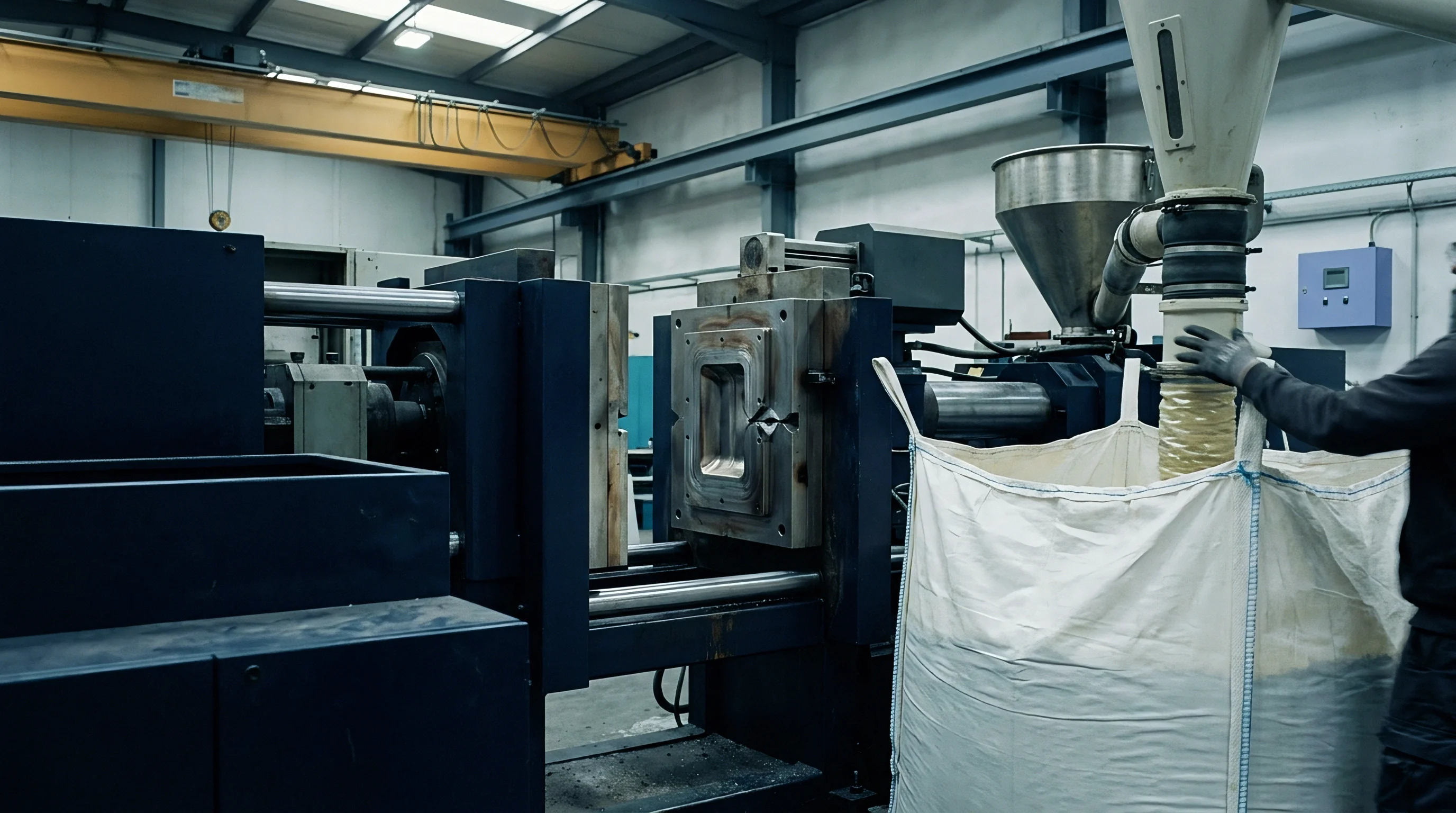
Finalizing a wall thickness modification during qualification requires updating technical documentation and quality records for full traceability. Keeping tool design records up to date ensures future maintenance, spare parts, and replacement inserts match the final off-tool geometry. After T2 or T3 sign-off, the engineering team updates 3D master CAD models, 2D drawings, steel detail prints, and mold flow simulation files.
A complete engineering change dossier captures all physical and process adjustments made during qualification. This package gives quality teams and production setters clear operational boundaries for daily production runs. Having detailed steel modification records also prevents disputes when tools transfer to secondary plants or contract molders.

Documentation Requirements for Engineering Change Orders
A complete qualification change package incorporates specific technical records validating modified wall geometry:
- Revised 3D CAD master models tagged with version control numbers and revision histories showing modified core and cavity boundaries.
- Annotated 2D drawings highlighting modified wall dimensions, rib-to-wall ratios, updated draft angles, and revised general tolerances.
- CMM inspection reports providing 30-piece process capability data (Cp and Cpk) across all altered features under target DIN 16742 standards.
- Toolroom modification logs detailing machining processes, electrode burn depths, welding material certs, and heat-treat stress-relief records.
- Scientific moulding process sheets recording nozzle temperatures, cavity pressure traces, gate seal times, and established process window limits.
Production sign-off hinges on achieving Cpk values above 1.33 for standard dimensions and 1.67 for critical mating features. When wall modifications touch functional interfaces, quality engineers sample 30 consecutive parts across three shifts to confirm dimensional stability under normal plant temperature swings. Proving process capability shows that the modified wall sections will hold dimensions over long production runs.

Integrating Quality Inspection into Serial Production
Routine production monitoring relies on quality checks tailored to the modified geometry. Inspectors use cross-sectional cutaways with optical comparators, or non-destructive ultrasonic pulse-echo thickness gauges, to verify wall uniformity without destroying finished parts. Ultrasonic gauges measure wall thickness quickly by tracking high-frequency sound reflections off the back wall.
In-line quality teams establish visual boundary samples ~ limit boards ~ defining acceptable thresholds for minor sink, weld line visibility, and surface texture across modified walls. These physical standards prevent subjective rejections by operators and clarify acceptance criteria on the floor. Combining physical limit samples with automated cavity pressure monitoring prevents shipping parts with voids or sink marks caused by brief pressure drops.
Final sign-off transfers tool ownership from the toolmaker to the production plant, locking in the modified wall geometry as the binding quality baseline. Production archives the qualification dossier alongside first-article retain samples to maintain complete quality traceability across the tool’s multi-year lifecycle.