Integrating Piezoelectric Sensors into High Cavitation Micro Injection Moulding Tools
Integrating piezoelectric sensors into high cavitation micro tools requires precise pocket fits, shielded wiring, and 10 kHz logging to balance filling across pins.

Bore
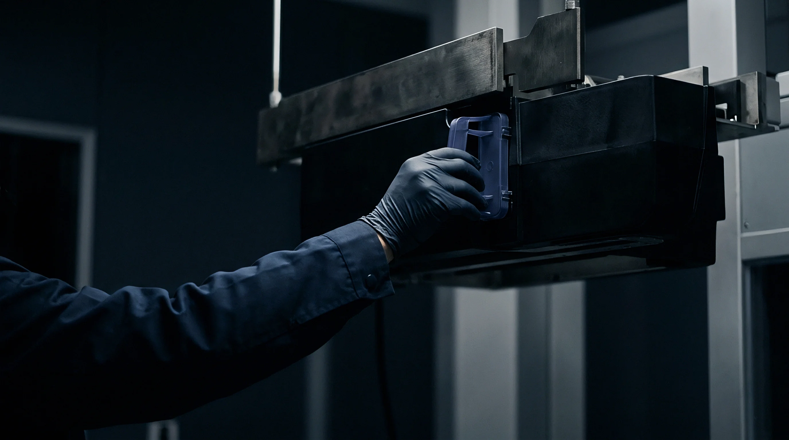
A 0.015-gram polyoxymethylene micro-gear running in a 32-cavity tool leaves no room for mechanical compromise. Toolmakers face center-to-center cavity pitches as narrow as 12.0 mm, where placing a traditional 4.0 mm quartz pressure transducer directly into the parting surface destroys the water jacket layout. Pocket placement shifts to sub-miniature 1.0 mm sensor pins or indirect load cells resting behind hardened ejector pins.
Steel selection for the sensor sleeve demands DIN 1.2343 ESR tool steel tempered to 54 HRC to prevent bore wall deformation under 1,400 bar cavity pressure spikes.
Melt freezes rapidly here. High cavitation tools distribute molten resin through balanced runner layouts where micro-gates freeze within 0.25 seconds. Placing the measuring face at the end of the flow path registers switchover events, while gate-adjacent placement captures the real peak holding pressure.
Cavity spacing dictates sensor diameter.
A 1.0 mm sensor pin installed with 0.005 mm diametral clearance flashes within twenty thousand cycles when processing polyoxymethylene at melt pressures above 1,200 bar.

Pocket Machining and Sleeve Fits
Wire electrical discharge machining cuts the sensor bore to an H7 tolerance band, maintaining a maximum runout of 0.003 mm across the depth of the cavity insert. Grinding the sleeve OD to an h6 fit delivers the required sliding contact without allowing radial deflection during injection shocks. When clearance exceeds 0.006 mm, low-viscosity melts such as liquid crystal polymers or unfilled polyamides enter the annular gap.
The polymer cures around the sensor tip, locking the pin axial movement and destroying signal linearity.
Steel shifts under clamp tonnage. Micro-injection tools run on clamping forces between 50 kN and 150 kN, concentrated over platen areas smaller than 200 mm by 200 mm. Platen deflection transfers compressive loads through the cavity inserts directly into the sensor mounting shoulder.
Toolmakers grind a stress-relief step of 0.02 mm on the backing plate to isolate the transducer body from structural tool clamp loads.
Direct Diaphragm against Indirect Pin Configurations
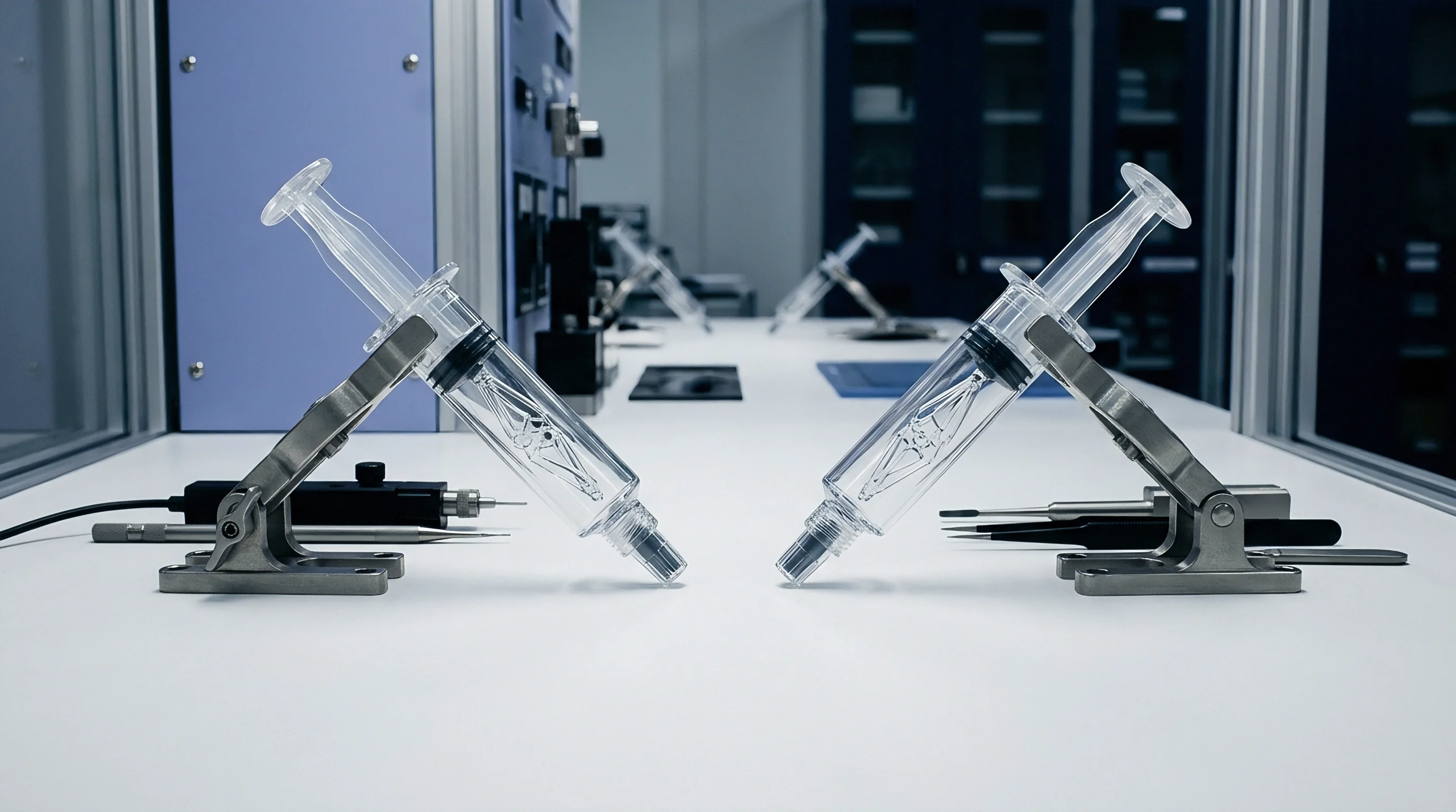
Direct-contact transducers place a flat quartz diaphragm flush with the cavity wall, eliminating mechanical friction from moving ejector pins. Diaphragm sensors leave a 1.0 mm witness circle on the finished component show face, which medical device specifications frequently forbid on micro-fluidic channels or optical lenses. Indirect installations route the melt force through an existing 0.5 mm or 0.8 mm ejector pin to a miniature load washer mounted in the ejector plate.
Micro pins bend under side loads. Unbalanced flow paths inside non-symmetrical micro cavities exert lateral forces against the ejector pin shaft, driving the pin against the bore wall. The resulting frictional hysteresis distorts the force transmission ratio between the cavity face and the underlying quartz crystal, producing false pressure drops of up to 15 percent on the press terminal.
- Annular melt ingress seizes the sensing pin inside the bore when diametral clearances open past 0.005 mm during sustained production shifts.
- Thermal boundary degradation shifts the quartz sensor sensitivity by 0.02 percent per kelvin when cooling channel distances drop below 3.0 mm from the sleeve.
- Preload loss at the retaining plate drops the transducer baseline charge output, causing false trigger signals during the machine velocity-to-pressure switchover.
- Pin bending under asymmetrical gate pressure creates frictional drag against the cavity wall, producing artificial pressure valleys in the holding phase trace.
| Installation Parameter | Direct Diaphragm (1.0 mm Head) | Indirect Ejector Pin (0.5 mm Pin) | Indirect Load Washer (1.5 mm Pin) |
|---|---|---|---|
| Sensor Pocket Diameter Tolerance | H7 (+0.010 mm / -0.000 mm) | H6 (+0.008 mm / -0.000 mm) | H7 (+0.012 mm / -0.000 mm) |
| Pin-to-Bore Diametral Clearance | None (Integrated Front Face) | 0.003 mm to 0.005 mm | 0.004 mm to 0.006 mm |
| Recommended Tool Steel Hardness | 52 to 54 HRC | 54 to 56 HRC | 50 to 52 HRC |
| Part Surface Witness Mark | 1.0 mm circular witness ring | 0.5 mm ejector pin witness | 1.5 mm ejector pin witness |
| Signal Hysteresis Error Band | 0.5 percent full scale | 3.0 to 6.5 percent full scale | 2.0 to 4.5 percent full scale |
| Maximum Cavity Pressure Limit | 2,000 bar | 2,500 bar | 2,000 bar |
The tooling vendor maintains that micro-pin binding occurs solely because the moulding technician applied grease unevenly during weekend maintenance.


Wire
Milling conduit channels across the backing plates demands strict separation between high-voltage manifold heater lines and low-noise coaxial sensor lines. In a 64-cavity micro-mould, routing 64 individual 1.2 mm cables creates an intricate maze inside the tool steel that weakens the structural support pillars. Sensor leads exit each sub-insert through dedicated ground slots cut by EDM, curving with a minimum bend radius of 15 mm to preserve the inner fluoropolymer dielectric layer.
Cables fail under platen motion. Multi-cavity tools cycle every 3.5 seconds on fast-cycling electric micro-presses, generating mechanical vibrations that fatigue unanchored wires inside the clamping plates. Toolmakers clamp cables every 50 mm using brass retaining straps screwed directly into tapped holes in the ejector retainer plate.
Cable bundles routed near heater bands lose insulation resistance long before the tool reaches its first scheduled maintenance overhaul.

Conduit Routing in Clamping Plates
Cable ways cut into the tool steel must never intersect water transfer rings or o-ring sealing counterbores. Coolant seepage into signal channels degrades the cable insulation resistance, which drops the piezoelectric charge signal from giga-ohms down to mega-ohms within hours. The tool designer positions the main collection channel along the neutral axis of the backing plate, venting moisture through open drain slots on the bottom tool face.
Direct sensors leave pin witness marks. Grouping thirty-two or sixty-four lines into a unified industrial connector requires multi-channel terminal blocks mounted on the non-operator side of the mould frame. Molders select heavy-duty rectangular housings containing gold-plated BNC or miniature LEMO pins, isolating each signal return to prevent ground loops across the machine platen.

Thermal Isolation and Electrical Shielding
Operating temperatures inside hot-runner micro-tools often hover around 280 degrees Celsius at the nozzle manifold, while the cavity blocks circulate water at 80 degrees Celsius. Sensor cables crossing these thermal boundaries experience thermal shock that degrades standard PVC or polyurethane outer jackets. Teflon-coated coaxial lines rated for continuous 200 degrees Celsius operation prevent short-circuiting against hot manifold components.
Heater bands emit intense electromagnetic fields during pulse-width-modulated power bursts. When an unshielded transducer cable runs parallel to a 230-volt cartridge heater lead, inductive coupling superimposes a 50-hertz oscillation over the cavity pressure trace. This artificial ripple distorts the digital peak detection algorithm, causing erroneous reject ejections on micro-parts that actually held perfect dimensional tolerance.
- Dielectric breakdown under thermal soaking lowers insulation resistance below the 100-teraohm threshold, causing rapid signal drift toward zero.
- Shearing against sharp pocket shoulders cuts through braided outer conductors when ejector plate travel misaligns the internal harness slack loop.
- Electromagnetic coupling from heater cables injects false pressure spikes into the charge amplifier, tripping cosmetic over-packing alarms during the cycle.
- Moisture contamination inside multi-pin blocks creates high-impedance leakage paths that invalidate multi-cavity pressure balancing calculations across the shift.
Pinched signal lines inside the plate stack ground the circuit, blinding the process controller and delivering full batches of short-shot micro-gears directly into the customer sorting bin.


Charge
Quartz crystals convert applied mechanical force into an electrical electrostatic charge proportional to the stress tensor acting across their crystallographic planes. In micro injection moulding, where fill times span 15 to 50 milliseconds, the transducer outputs between -2.0 and -5.0 picocoulombs per bar of cavity pressure. The charge amplifier converts this minuscule packet of electrons into a calibrated 0 to 10-volt analog signal for the press processing unit.
Charge amplifiers require daily resetting. The amplifier operational integrator accumulates drift from electrostatic air charges, internal cable leakage, and ambient humidity fluctuations. Resetting the measuring circuit to zero volts between cycles eliminates cumulative drift across thousand-shot production sequences.
Signal drift ruins holding pressure calculations.
Dynamic quartz sensors capture the precise millisecond of gate freeze while hydraulic machine pressure transducers register only continuous accumulator decay.

Piezoelectric Quartz Behavior under Micro Strokes
High-speed injection units achieve injection speeds up to 1,000 mm/s to fill 0.05 mm wall thicknesses before thermal freeze-off occurs. At these rates, the rising pressure wave hits the sensor face with a slew rate exceeding 500 bar per millisecond. Piezoelectric quartz elements possess natural resonant frequencies above 100 kHz, responding instantly without the mechanical damping that plagues melt-pressure strain gauges.
Thin walls freeze during injection. Melt front arrival registers on the oscilloscope as a sharp inflection departing from baseline, providing the exact timestamp for volumetric cavity filling. Charge sensitivity calibration rests on static deadweight testing protocols at 20 degrees Celsius, yielding -4.2 pC/N for typical 1.0 mm pins.
Subjecting the sensor to cyclic thermal shocks at 180 degrees Celsius shifts this sensitivity value downward by 3.5 percent over ten thousand cycles if cooling channel walls deviate by more than two millimeters from the sensor pocket.
Scientific deep-space telemetry instruments and ballistic detonation gauges face identical electrostatic charge dissipation issues when recording microsecond transients under extreme thermal shifts. The physical behavior of quartz under dynamic stress remains mathematically uniform whether measuring muzzle blast pressures or molten polyether ether ketone filling an electronic connector housing.

Dynamic Calibration and Drift Compensation
Sampling frequency governs measurement fidelity in micro-tooling instrumentation. A controller logging data at 100 hertz captures only two discrete pressure points during a 20-millisecond cavity fill, completely missing the peak hydrostatic compaction point. Industrial data acquisition cards must run analog-to-digital conversion at minimum rates of 10 kHz per channel across all cavities simultaneously.
Thermal gradients skew piezoelectric sensitivity. The 15 millisecond response time benchmark for melt front detection during a 45 millisecond micro-injection stroke rests on published cavity pressure studies across 1,200 consecutive cycles of polyoxymethylene. This response window shifts outward to 28 milliseconds if the barrel melt temperature drifts upward by 10 kelvins, altering the effective polymer viscosity and shear rate at the gate entrance.
- Mount the preloaded sensor inside the calibration test fixture and torque the retaining sleeve to the specified 1.2 Nm limit.
- Connect high-insulation coaxial cabling to the digital charge meter, verifying resistance values exceed 100 teraohms.
- Apply a calibrated compressive step load of 500 N using a deadweight hydraulic comparator while logging voltage decay.
- Record the discharge time constant to verify cable capacitance remains below 120 picofarads per meter of line.
- Calculate the sensitivity coefficient in picocoulombs per bar, entering the correction value into the press channel processor.
| Operational Characteristic | Micro Cavity Parameter | Conventional Cavity Parameter | Measurement Impact |
|---|---|---|---|
| Charge Sensitivity Range | -2.1 to -4.5 pC/bar | -10.0 to -25.0 pC/bar | Demands ultra-low noise amplifiers |
| Cavity Pressure Fill Slew Rate | 300 to 750 bar/ms | 20 to 80 bar/ms | Requires 10 kHz sampling frequency |
| Signal Drift Rate Limit | < 0.05 pC/s at 80 °C | < 0.01 pC/s at 40 °C | Integrator reset required every shot |
| Frequency Response Ceiling | > 120 kHz | > 50 kHz | Captures sub-millisecond gate freeze |
| Operating Temperature Window | -40 to 200 °C | -40 to 120 °C | Compensates for rapid thermal cycling |
Molders still debate whether sub-millisecond charge amplification can ever isolate localized viscous heating from true hydrostatic pressure during the final fractions of a milligram of cavity fill.
Scatter
Distribution profiles across 32 or 64 cavities reveal immediate thermal and rheological unbalance that no hydraulic press gauge can detect. In a 32-cavity micro-connector tool, inner cavities positioned near the main sprue drop receive polymer at higher temperatures and lower viscosities than peripheral cavities. Peak cavity pressures across identical impressions can vary by 25 percent despite steel dimensions held to plus or minus 0.002 mm across every core pin.
Switchover timing governs gate seal consistency. Micro-moulded components rely on holding pressure to pack out volumetric shrinkage, which averages 2.2 percent in semi-crystalline materials. Terminating the holding phase before peripheral micro-gates freeze induces melt backflow into the runner, leaving parts short on mass and out of round.
Specifying tolerance group TG3 under DIN 16742 forces the moulder to scrap entire multi-cavity shots whenever two opposing cavities experience a three percent divergence in peak compression.

Cavity Pressure Trace Imbalance across Impressions
Imbalance originates in shear-induced heating within the runner manifold branches. Molten resin traveling through right-angle runner junctions experiences asymmetrical shear distributions, sending higher-temperature melt layers to the inner quadrant cavities. Cavities filling with lower-viscosity melt show steeper pressure rise curves and reach packing pressure earlier than outer impressions.
Drift accumulates across prolonged cycle runs. Machine setters tune switchover from injection speed to holding pressure based on a single master cavity sensor trace. If master cavity 1 fills four milliseconds ahead of cavity 32, switching the screw over on cavity 1 peak pressure starves cavity 32, producing short shots or sink marks on functional gear teeth.

Gate Freeze Identification and Switchover Control
Gate seal studies plot the integral of cavity pressure over time against varying holding pressure durations. The exact millisecond of gate freeze appears on the sensor curve where the pressure decay slope stabilizes into pure thermal cooling contraction. Any continued machine holding pressure applied after this inflection point wastes energy and induces mechanical stress into the hot-runner tips.
Dynamic switchover triggered by cavity pressure eliminates transfer fluctuations caused by non-return valve leakage in the injection barrel. Check rings in micro-injection screws slip by fractions of a millimeter during screw forward movement, varying the effective shot cushion by up to 30 percent. A cavity sensor detects melt arrival at the part boundary, sending a digital interrupt to switch the machine into holding mode exactly when the cavity fills.
- Master cavity sensor selection assigns the trigger channel to the slowest-filling peripheral cavity to eliminate short-shot defects on all remaining parts.
- Pressure integral window boundaries establish strict rejection limits for each shot based on the calculated area beneath the holding pressure curve.
- Automated parts separator gate routing diverts entire shots to the reject container when individual cavity peak pressures diverge past five percent.
- Manifold tip temperature adjustment balances cavity fill times by raising outer nozzle setpoints by two to five kelvins relative to center nozzles.
A runner system that balances cold water flow will never balance molten polymer across thirty-two micro gates.


Outlay
Budgeting for full-cavity instrumentation changes the capital allocation for micro-injection tooling projects. Sensor hardware, high-temperature coaxial leads, multi-channel junction boxes, and digital charge amplifier racks add between 1,200 and 1,800 euros per cavity to the base tool construction invoice. In a 64-cavity high-precision tool, this instrumentation package adds over 90,000 euros to the initial purchase order, frequently representing 35 percent of the total toolmaking expenditure.
Scrap rates drive total tooling amortization. Micro medical mouldings running at hundred-thousand-unit weekly volumes cannot endure manual optical sorting on microscope stages. Automated rejection gates driven by cavity pressure integrals catch out-of-spec parts press-side, cutting quality inspection overhead and preventing contaminated lots from reaching assembly cleanrooms.
Quoted sensor longevity figures claim a 500,000-shot mean-time-between-failures for 1.0 mm indirect ejector-pin sensor heads under production conditions. Field operation reveals sensor head failure anywhere between 180,000 and 750,000 shots depending on injection speed, resin abrasiveness, and tool maintenance consistency. Prudent procurement teams include contractual provisions obligating the toolmaker to supply three complete sensor replacement sets and spare pin sleeves with the initial tool delivery.
Tooling Amortization and Sensor Longevity
Tool amortization models evaluate the capital expenditure against scrap reduction over the operational life of the mold. A 32-cavity tool producing polyoxymethylene medical micro-clips at a three-second cycle generates over 25 million parts per year. Reducing the scrap rate from 4.5 percent down to 0.4 percent via cavity pressure monitoring recovers the entire 48,000-euro sensor investment within 4.2 months of commercial production.
Toolmakers measure tolerances at twenty degrees. Running production at elevated mold temperatures causes thermal growth that alters sensor preloads if backing plates lack ground expansion allowances. Proper preventive maintenance schedules mandate removing and ultrasonically cleaning sensor pins every 200,000 cycles to extract pyrolyzed polymer vapors that migrate down ejector clearances.

Factory Acceptance Testing and Cavity Sign Off
Tool validation protocols require run-at-rate verification across minimum 5,000-shot pilot trials before releasing final tool balance payments. The tool qualification dossier documents pressure trace repeatability across all cavities simultaneously, verifying standard deviations remain below 2.0 percent for peak injection pressure. Cavities exhibiting irregular baseline charge drift or delayed pressure rise curves must be disassembled and checked for pin binding before shipping the tool across borders.
Procurement contracts protect the buyer by tying tool sign-off directly to international tolerance standards. Acceptance criteria based on DIN 16742 establish clear numerical thresholds for dimensional capability indices, demanding Cpk values above 1.67 across critical dimensions on all cavitated parts. Without cavity pressure instrumentation, proving multi-cavity Cpk capability requires measuring thousands of micro-parts on coordinate measuring machines, burning valuable qualification weeks.
| Tool Cost and Operational Element | Uninstrumented Tooling | Master-Cavity Only (4 Sensors) | Full-Cavitation (32 Sensors) |
|---|---|---|---|
| Initial Sensor Hardware and Amp Outlay | 0 EUR | 6,800 EUR | 46,500 EUR |
| Toolroom Machining and Wiring Surcharge | 0 EUR | 2,400 EUR | 12,800 EUR |
| Annual Preventative Maintenance Budget | 1,500 EUR | 3,200 EUR | 8,500 EUR |
| Average Scrap Rate Across Shift | 5.2 percent | 2.8 percent | 0.3 percent |
| Automated Shot Sorting Integration | Unavailable | Quadrant Level Only | Individual Shot Rejection |
| Payback Horizon at 20M Parts/Year | Baseline | 2.1 Months | 4.4 Months |
| Cost basis assumes a 32-cavity tool producing a 0.02 g technical POM part on a 3.2 s cycle time with machine hour rates calculated at 65 EUR/hour. | |||
Incorporating clause 8.4 of DIN 16742 into the purchase contract transfers all sensor replacement expenses and requalification press time to the toolmaker whenever individual cavity pressure variance exceeds five percent during the initial fifty thousand production shots.