Sub Micron Flexure Sleeve Wear Dynamics in Continuous Piezo Driven Micro Injection Cavities
Continuous piezo flexure sleeves require physical clearances below 0.5 micrometers and diamond-like carbon coatings to prevent micro-galling under thermal loads.

Kinematics
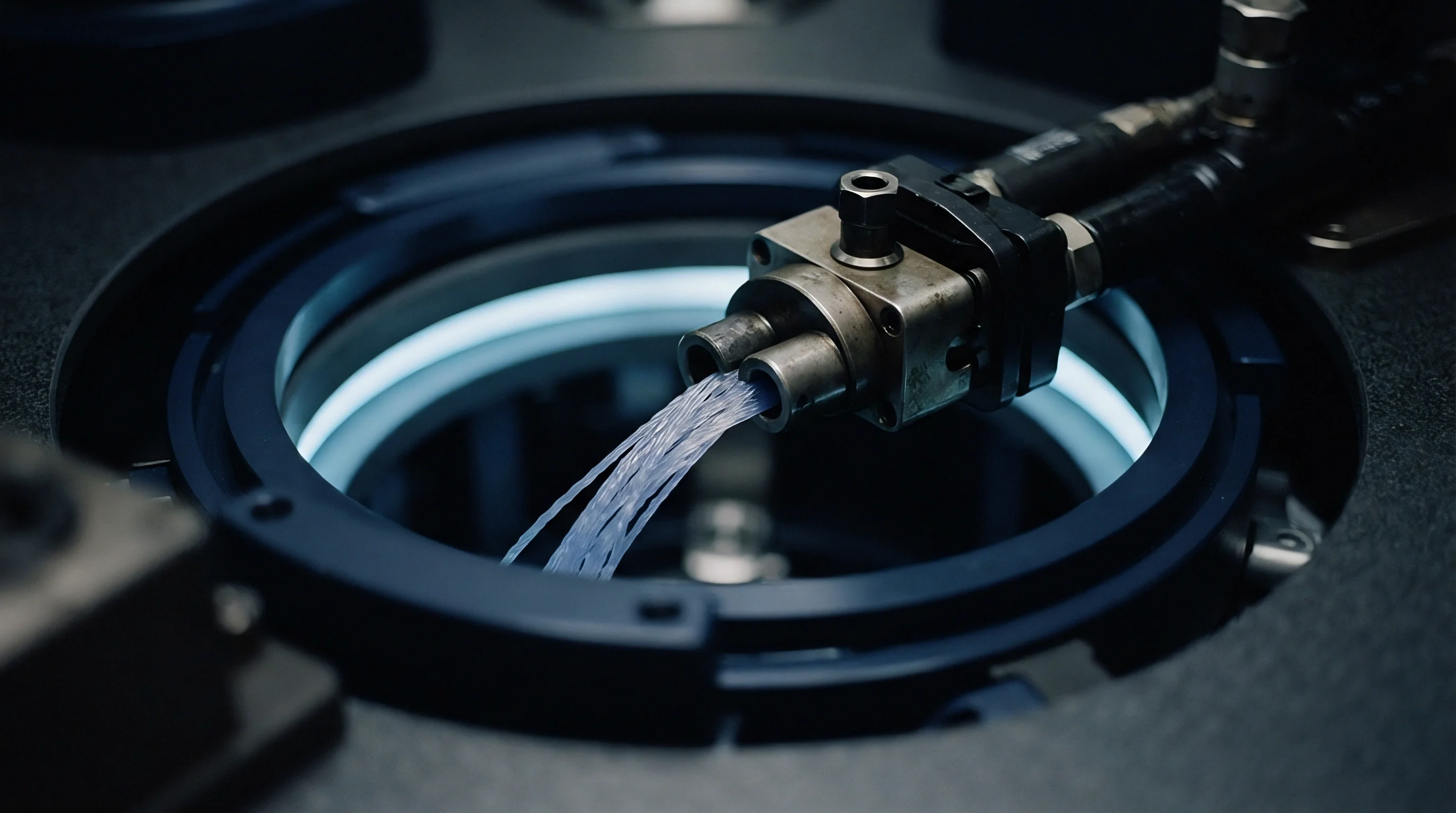
Direct piezo actuation within micro injection tooling shifts mechanical stroke generation from external hydraulic platens into the core insert. When driven by applied voltage steps, piezoelectric ceramic stacks expand along their polarization axis within microseconds. Integrating these stacks behind guided cavity inserts allows active compression during the polymer melt fill phase.
Machined flexure hinges cut directly into titanium or hardened tool steel housings eliminate mechanical backlash, play, and external sliding friction. This monolithic arrangement provides pure linear motion across displacement ranges from 0.5 micrometers to 50 micrometers at continuous operational frequencies reaching 200 Hertz.
Running at these cycle rates subjects the flexure sleeve to heavy cyclic loading. During the injection stroke, hydraulic melt pressure pulses exceeding 1800 bar act directly against the sleeve face. The piezo actuator must deliver sufficient blocking force to hold positional accuracy against this counter-acting fluid force.
Elastic flexure blades deflect predictably within their fatigue limits, provided operating stresses remain below forty percent of the substrate yield strength. The structural stiffness of the flexure sleeve determines both the natural frequency of the moving assembly and the stroke attenuation caused by melt reaction pressure.
An uncompensated temperature rise of 12 Kelvin across a grade 1.2083 tool steel housing reduces a 0.6 micrometer sleeve clearance to zero.
Continuous cycling generates substantial internal friction within piezo ceramic stacks and flexure guide points. Thermal energy dissipates into the surrounding tool insert, establishing localized temperature gradients that alter the precision gap between the oscillating flexure sleeve and the stationary cavity core. A misalignment of 0.2 micrometers across the sleeve axis increases asymmetrical lateral contact forces.
As lateral forces rise, elastic flexure deflection shifts into localized sliding contact along guided land surfaces.
Continuous micro-injection cycles require precise control of the voltage waveform fed into the piezo drive modules. Tailoring trapezoidal or sinusoidal voltage profiles shapes the velocity and acceleration of the flexure sleeve. Rapid acceleration spikes induce structural ring-down, causing transient positioning errors at the end of the stroke.
Damping these resonance oscillations requires passive viscoelastic elements or active closed-loop voltage modulation. Left unchecked, resonance accelerates fatigue damage across flexure hinge sections and drives micro-scale contact scrubbing between adjacent sleeve interfaces.

Scuff
Fretting wear along guided sleeve surfaces originates from micro-amplitude cyclic sliding between metal interfaces under high compressive contact pressure. In micro-injection moulding cavities, organic liquid lubricants risk severe melt contamination and part rejection. Tooling surfaces operate without standard oil film lubrication.
Unlubricated sliding across contact lands narrower than 2.0 millimeters concentrated under multi-megapascal normal loads removes passivating surface oxides. Clean metallic surfaces contact directly, forming micro-junctions that shear during subsequent displacement cycles.
Microscopic metallic particles detached during initial running-in phases become trapped within the sub-micron sleeve gap, oxidizing under ambient cavity temperatures reaching 220°C. Hard oxide debris acts as a three-body abrasive medium, scratching guided surfaces and widening the operational clearance. As clearance widens, polymer melt under high pressure leaks into the sliding interface, causing sleeve flash, mechanical binding, and total actuator lockup.
Selecting appropriate hard thin-film coatings limits adhesive surface transfer. Physical vapor deposition deposits dense ceramic or carbon-based coatings onto prepared sleeve substrates. Chrome nitride, titanium aluminum nitride, and tetrahedral hydrogen-free diamond-like carbon offer high micro-hardness exceeding 2500 Vickers.
These thin films lower dry friction coefficients against tool steel from 0.8 down below 0.15. The coating thickness must remain strictly controlled between 1.0 micrometer and 2.5 micrometers to maintain dimensional integrity within sub-micron tolerances.
| Coating Architecture | Hardness (HV 0.05) | Coefficient Of Friction | Coating Thickness (µm) | Wear Rate (10⁻⁶ mm³/Nm) |
|---|---|---|---|---|
| Uncoated Tool Steel | 580 | 0.78 | 0.00 | 14.20 |
| Chromium Nitride (CrN) | 2200 | 0.42 | 2.10 | 1.85 |
| Titanium Aluminum Nitride (TiAlN) | 3100 | 0.35 | 1.80 | 0.92 |
| Hydrogen-Free DLC (ta-C) | 4500 | 0.12 | 1.20 | 0.15 |
| Tungsten-Modified DLC (W-DLC) | 1800 | 0.18 | 2.40 | 0.48 |
Interface compatibility between the flexure sleeve substrate and the stationary core housing determines coating performance under shear stress. Applying identical ceramic coatings to both contact surfaces increases the risk of micro-welding under cyclic fretting loads. Asymmetrical tribological pairs, such as a hydrogen-free diamond-like carbon sleeve against a chromium nitride housing, prevent intermetallic bonding and extend running life beyond ten million cycles.
- Adhesive Galling localized surface tearing and material transfer caused by unlubricated metal-to-metal contact under high lateral compression forces
- Three-Body Abrasion scoring of polished guide surfaces by trapped metal oxide debris or degraded polymer residues within sub-micron clearances
- Surface Delamination subsurface fatigue cracking and spalling of thin PVD coatings due to cyclic contact stress exceeding substrate shear strength
- Thermal Ratcheting progressive loss of running clearance caused by differential heat accumulation between the active sleeve core and static housing
Hard thin coatings prevent adhesive material transfer only when the underlying substrate yield strength exceeds the contact stress imposed by thermal deflection.
Ignored wear dynamics allow micro-clearances to open from 0.5 micrometers beyond 3.0 micrometers during continuous production. High pressure polymer melt enters the enlarged gap, forming flash webs on micro-moulded components that jam downstream automated handling systems and force unscheduled tool tear-downs.


Metrology
In-situ displacement tracking inside an active micro injection tool requires non-contact sensor architectures capable of sub-nanometer resolution. Contact probes introduce mechanical loading that alters the motion of high-frequency flexure sleeves. Fiber-optic capacitive sensors embedded within static tool inserts measure flexure displacement directly from targeted reference faces.
High sensor bandwidth exceeding 50 Kilohertz captures dynamic sleeve tilt, position overshoot, and structural ring-down during fast piezo actuation steps.

Why Do Sub Micron Flexure Clearance Drift Bands Exceed Thermal Growth Limits?
Asymmetrical heat generation across the piezo actuator stack drives non-uniform expansion along the guide axis. Electric field hysteretic losses within PZT ceramic stacks generate internal thermal loads directly proportional to operating frequency. Conductive transfer into the tool steel housing occurs unevenly across surrounding water cooling channels.
The resulting local thermal expansion alters core concentricity, causing the flexure sleeve to tip by fractions of a micrometer. This angular tilt concentrates lateral mechanical contact on opposite diagonal corners of the guide land, accelerating localized abrasive wear.
- Mount the core insert within an isolated temperature-controlled metrology fixture.
- Connect fiber-optic capacitive probes to calibrated signal conditioning amplifiers.
- Apply stepped DC voltage pulses from 0 to 150 Volts to establish baseline static voltage-to-displacement curves.
- Execute continuous high-frequency AC sweep cycles from 10 Hertz to 1000 Hertz to capture dynamic transfer functions.
- Record high-speed laser doppler vibrometer measurements on the flexure face to cross-verify capacitive sensor output.
- Process raw displacement data through high-pass filtering algorithms to isolate high-frequency vibration from low-frequency thermal drift trends.
Per DIN 16742 Group 1 precision tolerances, cavity sleeve tilt exceeding 0.3 micrometers invalidates dimensional compliance for optical micro-array moldings.
Isolating mechanical flexure deflection from thermal housing growth requires differential measurement loops. Dual-channel capacitive systems position one probe target on the moving sleeve face and a second target on the stationary cavity insert. Subtracting the stationary signal from the total displacement signal removes bulk thermal expansion shifts.
This differential signal isolates pure flexure stroke, enabling automated press controller compensation through real-time piezo voltage bias adjustments.
Sub-micron alignment guarantees derived from static room-temperature bench calibrations fail to reflect real operating conditions. Hot melt contact, continuous voltage cycling, and active tool cooling circuits establish severe internal thermal gradients that ambient bench setups do not reproduce.

Tolerance
Dimensional allocation for high-frequency micro flexure assemblies requires tight manufacturing limits on both guided sleeves and static housings. Wire electrical discharge machining achieves contour accuracy within 1.0 micrometer on hardened tool steels. Sub-micron guide fits demand secondary finishing operations.
Femtosecond laser ablation and precision magnetorheological polishing smooth eroded surface peaks, bringing surface roughness below Ra 0.02 micrometers without altering geometric concentricity.
| Fit Designation | Bore Tolerance (µm) | Sleeve Tolerance (µm) | Initial Clearance (µm) | Max Operational Clearance (µm) |
|---|---|---|---|---|
| Precision Micro Fit (PMF-1) | +0.3 / 0.0 | 0.0 / -0.3 | 0.2 to 0.6 | 1.2 |
| Standard Flexure Fit (SFF-2) | +0.5 / 0.0 | 0.0 / -0.5 | 0.4 to 1.0 | 2.0 |
| High-Thermal Fit (HTF-3) | +0.8 / 0.0 | 0.0 / -0.8 | 0.6 to 1.6 | 3.2 |
| Loose Guide Fit (LGF-4) | +1.2 / 0.0 | 0.0 / -1.2 | 1.0 to 2.4 | 4.5 |
Calculating the thermal stack-up across a multi-material assembly requires accounting for coefficient of thermal expansion mismatches between materials. PZT ceramic stacks expand at approximately 1.5 x 10⁻⁶ / K along their polarization axis, whereas stainless steel housings expand at 10.5 x 10⁻⁶ / K and titanium flexures at 8.6 x 10⁻⁶ / K. Uncompensated thermal growth closes designed running clearances, leading to mechanical interference during operation.
- Material Substrate Matching select flexure alloys and housing steels with thermal expansion coefficients within 1.0 x 10⁻⁶ / K to limit temperature-induced clearance shifts
- Sub-Micron Roughness Control specify magnetorheological or laser polishing on all guided lands to maintain surface finish below Ra 0.02 micrometers
- Asymmetrical Coating Selection apply distinct PVD surface treatments to sliding pairs to prevent adhesive bonding under dry running conditions
- Active Thermal Stabilization incorporate dedicated oil cooling channels directly behind piezo cavities to control core temperature within 1.0 Kelvin
According to ISO 286 Grade IT1 specifications, cylindrical sleeve features with diameters under 5.0 millimeters must hold roundness within 0.25 micrometers. Deviations from true circularity create high local pressure points along guided lands, causing localized coating wear, accelerated debris generation, and early fatigue failure of the flexure support structure.
Sourcing
Integrating piezo-driven flexure technology into high-cavitation production tooling increases capital expenditure for micro-moulding programs. Active piezo cavity inserts increase initial tool fabrication costs by $12,000 to $22,000 per cavity relative to conventional passive core tooling. This initial capital expenditure must be evaluated against unit cost savings generated through reduced injection cycle times and higher part yield.
Active piezo flexure sleeves accelerate part ejection and enable melt compression micro-moulding. In thin-wall optical lens arrays, active compression lowers required injection pressures, reducing cooling time requirements. Consider a 16-cavity tool producing poly-methyl methacrylate micro-fluidic chips with a 1.2-second cycle time reduction achieved through active piezo sleeve compression.
At an operating shop-floor rate of $95 per press hour, annual savings across three shift operations offset the initial $240,000 piezo tooling premium within seven months of continuous production.
Active piezo tooling transfers cycle time risks from press setting adjustments to toolroom replacement schedules.
Tooling procurement contracts must address ownership and spare parts management for high-wear flexure components. Piezoelectric ceramic stacks exhibit finite operational lifespans under continuous high-frequency cycling. Depolarization, internal electrode delamination, and flexure fatigue require planned replacement intervals after 15 to 25 million cycles.
Sourcing specifications should require suppliers to deliver interchangeable, pre-calibrated flexure sleeve modules with verified sub-micron alignment protocols.
Supply agreements that lack explicit wear degradation clauses expose buyers to unrecoverable yield losses. When piezo flexure sleeves wear beyond functional limits, polymer flash formation forces press stoppages and manual core refurbishments. Procurement teams must define clear operational wear thresholds in tooling sign-off documents, establishing vendor warranty obligations for premature coating breakdown or sleeve binding during production runs.
How do tooling suppliers guarantee sub-micron flexure guidance alignment across multi-cavity inserts when thermal growth variances across large tool bolsters exceed two micrometers under normal molding conditions?