Optimizing Gate Geometry for Non Newtonian Melt Flow Dynamics
Size gate depth to wall thickness and expand width to keep shear rates below polymer degradation limits under non-Newtonian melt flow.


Rheology
Polymer melt entering a gate restriction experiences shear rates accelerating past 50,000 reciprocal seconds, collapsing apparent viscosity by up to two orders of magnitude within a travel distance of three millimeters. When an injection press drives a glass-filled polyamide through an undersized restriction, the pressure gauge spikes before the cavity registers any melt front advance. Sizing this restriction incorrectly produces immediate operational losses: burning, premature gate freeze, excessive injection pressure, or warpage driven by uncontrolled molecular orientation.
You size gates by calculating the real non-Newtonian viscosity under local shear and thermal conditions, directly linking tool dimensions to the material response.
Thermoplastic melts exhibit pseudoplastic shear-thinning behavior governed by polymer chain disentanglement. At rest or low shear rates, long-chain molecules remain randomly coiled, offering substantial resistance to flow. As flow velocity gradients steepen within restrictive gates, polymer chains align parallel to the streamlines.
The Ostwald-de Waele power law models this response across standard processing shear intervals:
tau = K (gamma_dot)^n
In this relationship, tau represents shear stress, K is the flow consistency index, gamma_dot is the shear rate, and n represents the power-law index. For pseudoplastic melts, n falls below unity. Highly shear-sensitive polymers such as polyoxymethylene and rubber-toughened polyamides display n values between 0.20 and 0.35.
Melt viscosity drops precipitously as shear rate climbs. Polycarbonate exhibits a stiffer backbone, yielding an n value between 0.65 and 0.75, which leaves its viscosity comparatively resistant to shear-thinning. Designing identical gate cross-sections for these two material classes produces severe cavity fill imbalances.
A thirty percent glass-filled polyamide processed at 285 degrees Celsius exhibits a seventy-fold drop in apparent viscosity as gate shear rates increase from one thousand to eighty thousand reciprocal seconds.
Process engineers rely on the Cross-WLF model for mold filling simulations, capturing both shear-thinning and temperature dependency across the complete injection velocity profile. The zero-shear viscosity eta_0 establishes the Newtonian plateau at minimal shear rates, while the parameter tau_star marks the transition shear stress where shear-thinning initiates. When your gate geometry generates shear stresses far beyond tau_star, small changes in gate diameter or land length create disproportionately large shifts in cavity fill pressure.
Toolmakers frequently overlook this non-linear sensitivity during steel adjustments.

Melt Elasticity and Normal Stress Differences
Viscoelastic fluids generate normal stress differences perpendicular to the primary flow direction whenever they pass through geometric convergences. As polymer chains squeeze into a narrow entrance, they store elastic strain energy. Upon exiting the gate into the expanded cavity volume, these chains recoil, causing extrudate swell, often termed die swell.
High melt elasticity amplifies this expansion, producing localized jetting when the entering melt stream cannot contact cavity walls immediately. Gate depth relative to adjacent wall thickness directly controls this transition.
Excessive shear exposure across gate orifices initiates irreversible polymer degradation. Chain scission occurs when local hydrodynamic forces exceed chemical bond energies, deteriorating mechanical performance in the finished component. Sourcing managers frequently inspect parts that match drawing dimensions perfectly yet fail drop-impact testing because severe gate shear destroyed polymer molecular weight during molding.
- Mechanical chain scission lowers tensile strength around the injection area while reducing elongation at break.
- Thermal degradation streaks produce splay marks and cosmetic silvery discoloration across Class-A cosmetic surfaces.
- Localized fiber attrition reduces glass fiber length from three hundred microns down to forty microns, stripping structural stiffness.
- Additive separation releases gaseous volatile compounds that deposit corrosive residue onto mold cavity vents.
Process stability deteriorates when gate dimensions force resin into thermal degradation territory. The following reference data outlines rheological parameters and allowable shear thresholds across common production thermoplastics.
| Polymer Chemistry | Glass Content (% wt) | Power-Law Index n | Transition Stress tau_star (Pa) | Max Shear Rate (1/s) | Typical Melt Temp (°C) |
|---|---|---|---|---|---|
| Polyamide 66 (PA66) | 0 | 0.32 | 28,000 | 60,000 | 285 |
| PA66 GF30 | 30 | 0.26 | 45,000 | 35,000 | 295 |
| Polycarbonate (PC) | 0 | 0.68 | 120,000 | 40,000 | 305 |
| Polyoxymethylene (POM) | 0 | 0.30 | 32,000 | 50,000 | 205 |
| Polyetheretherketone (PEEK) | 30 | 0.38 | 65,000 | 30,000 | 390 |
Melt viscosity curves flatten out once shear rates exceed resin degradation boundaries.
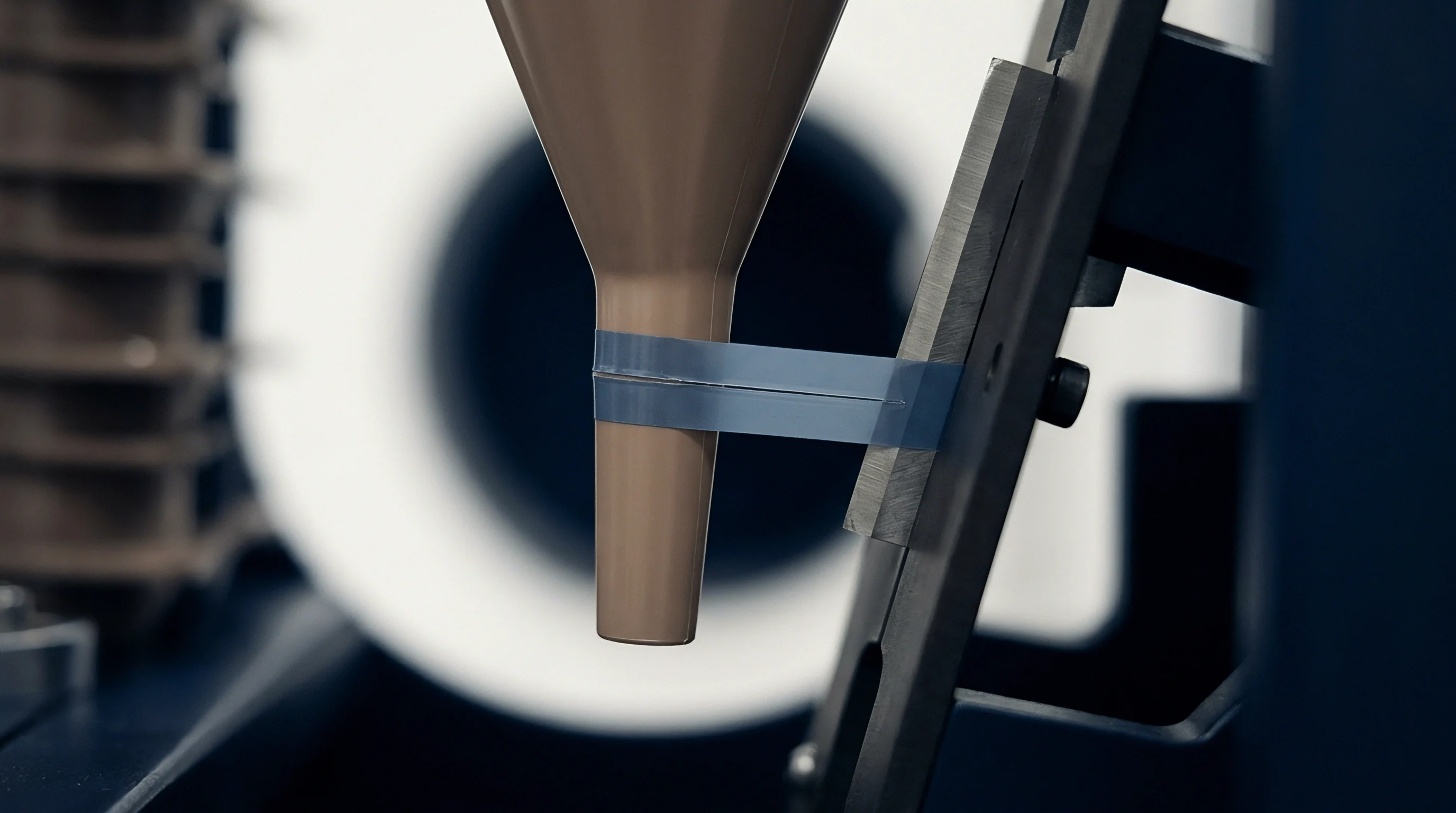

Orifice
Dimensional configuration of the gate cross-section establishes the shear rate field, total pressure loss, and packing time for the molded part. Gate depth governs the freeze-off window, whereas gate width controls volumetric fill rate without elevating wall shear stress. Tool designers frequently apply uniform gating dimensions across disparate polymers, ignoring the reality that pseudoplastic fluid dynamics dictate customized cross-sections for every resin family.
A gate cut too thin freezes before pack pressure transmits, leaving sink marks over thick ribs.
Calculating gate shear rate requires adapting classic Hagen-Poiseuille equations to account for non-Newtonian velocity profiles through the Weissenberg-Rabinowitsch correction. For a circular gate of radius R carrying volumetric flow rate Q, the true shear rate at the wall follows:
gamma_dot_wall = ((3 n + 1) / (4 n)) ((4 Q) / (pi R^3))
For a rectangular gate of width W, thickness H, where W exceeds H, the corrected apparent wall shear rate follows:
gamma_dot_wall = ((2 n + 1) / (3 n)) ((6 Q) / (W H^2))
When the power-law index n equals 0.3 instead of 1.0, wall shear rate climbs by thirty-two percent for an identical volume throughput. Gate land length represents the axial distance of the gate restriction before opening into the cavity. Long land lengths create severe pressure drops, causing setters to elevate melt temperature to fill the tool.
Keeping land length between 0.5 mm and 0.8 mm reduces this flow resistance.

Geometric Trade-Offs across Gate Types
Tool construction mandates matching gate geometry to part volume, resin rheology, and cosmetic vestige allowances. Submarine gates shear automatically during mold opening, reducing manual labor costs at the press. Pinpoint gates applied in three-plate tools decouple runner scrap from the molded part, yet generate extreme shear rates due to their restricted diameters.
Edge gates offer straightforward tool modification possibilities, permitting EDM sinker operations to widen the restriction without pulling core inserts.
| Gate Type | Typical Depth (mm) | Land Length (mm) | Flow Resistance | Degradation Risk | Vestige Class |
|---|---|---|---|---|---|
| Standard Edge | 0.60 to 0.75 wall | 0.75 to 1.00 | Moderate | Low | Visible witness |
| Submarine / Tunnel | 0.80 to 1.50 diameter | 0.50 to 0.75 | High | Moderate | Recessed break |
| Pinpoint (3-Plate) | 0.60 to 1.20 diameter | 0.50 to 0.75 | Extreme | Severe | Small nub |
| Fan Gate | 0.50 to 0.65 wall | 1.00 to 1.50 | Low | Low | Linear strip |
| Valve Gate Hot Runner | 1.50 to 3.00 diameter | Zero land | Minimal | Minimal | Flush stem mark |
Selecting an edge gate geometry over a restricted tunnel gate demands balancing post-molding trim costs against scrap rates caused by shear degradation. When edge gating glass-filled materials, toolmakers apply fan transitions to expand the flow front gradually. This gradual approach minimizes fiber breakage while orienting fillers parallel to the flow path, stabilizing part dimensions across the shrinkage axis.

Gate Sizing Procedure
- Determine nominal part wall thickness at the gate location, identifying the thickest cross-section to maintain holding pressure communication.
- Select preliminary gate depth based on resin crystallinity, assigning sixty percent of nominal wall thickness for amorphous grades and seventy-five percent for semicrystalline polymers.
- Calculate volumetric flow rate Q by dividing cavity volume by the targeted fill time established during flow simulation or press qualification.
- Compute the Weissenberg-Rabinowitsch wall shear rate using the corrected power-law formula, comparing the result against resin shear stress limits.
- Iterate gate width upward to bring computed wall shear rate below seventy percent of the resin critical threshold while leaving gate depth unchanged.
- Set gate land length to 0.60 millimeters, avoiding land expansion beyond 0.80 millimeters to prevent unnecessary pressure attenuation.
Machining a gate land longer than one millimeter increases the risk of premature solid layer growth inside the runner-cavity transition. As frozen layers constrict the open hydraulic diameter, injection pressure climbs exponentially, consuming machine clamp tonnage before the cavity reaches volumetric completion. Parts molded under these conditions display severe internal voiding, sink depressions opposite structural ribs, and dimension failures under ISO 20753 qualification standards.


Dissipation
Mechanical energy supplied by the injection screw converts into thermal energy as viscous polymer chains shear past one another in narrow steel restrictions. This viscous dissipation causes an instantaneous local temperature increase termed adiabatic shear heating. Because polymer melts possess low thermal conductivity, heat generated inside the high-shear gate core cannot escape into the tool steel during the fraction of a second required for mold filling.
The temperature spike concentrates within a thin boundary layer adjacent to the gate walls.
Calculating the temperature rise delta_T across a gate restriction relies on mechanical energy conversion models:
delta_T = (eta_eff delta_P) / (rho C_p)
In this equation, delta_P represents pressure drop across the gate, rho is melt density, C_p is specific heat capacity, and eta_eff is the thermal conversion efficiency, typically approaching 0.90 for high-speed filling. For an injection pressure drop of 80 MPa across an undersized tunnel gate running polycarbonate, local melt temperature spikes by 25 to 35 degrees Celsius above the set barrel temperature. This localized thermal surge routinely exceeds the thermal degradation temperature of the polymer.
A seventy megapascal pressure drop across a pinpoint gate elevates local melt temperature by thirty-one degrees Celsius in less than twelve milliseconds.
Thermal increases reduce melt viscosity, which accelerates flow velocity, triggering further shear heating. This feedback loop creates intense localized flow channeling through the gate center. Unfilled engineering polymers may tolerate modest temperature excursions, but flame retardants, impact modifiers, and organic colorants break down under short-duration thermal spikes.
Degraded additives outgas rapidly, etching the mold cavity steel near the gate and producing cloudy surface hazing on optical components.

How Viscous Heating Modifies Injection Pressure Demand?
Press hydraulic systems respond dynamically to non-Newtonian thinning amplified by viscous heat generation. As the melt front traverses the gate, initial resistance generates a sharp pressure peak. Once high-shear flow initiates, localized thermal softening reduces apparent viscosity, causing injection pressure traces to drop abruptly before cavity fill finishes.
Untrained operators misread this pressure drop as a sign of an oversized gate, leading them to reduce injection speeds. Dropping injection speed lowers shear rate, elevates resin viscosity, freezes the flow front, and causes short shots.
Controlling viscous dissipation requires tuning gate aspect ratio and injection speed profiles. Process setters utilize multi-step injection velocity profiles, starting with moderate speed through the sprue, reducing speed as the melt front traverses the gate orifice, and accelerating once the melt front expands safely into the cavity volume. This controlled deceleration minimizes peak shear rates while preserving rapid fill times across distant part features.
Thermal imaging during tool trials confirms that gate localized heat dissipation persists across high-speed cycles, leaving tool steel surrounding the gate thirty degrees hotter than distal mold regions. Whether localized gate cooling inserts can reliably dissipate this transient heat surge without causing premature skin freeze across the runner interface remains subject to press trials.


Vestige
Post-molding separation of the runner leaves residual material known as gate vestige, creating mechanical and cosmetic defects if unmanaged. The geometry of the gate fracture zone determines whether the break point occurs flush with the part surface, projects outward as a sharp burr, or pulls a divot out of the nominal wall. Non-Newtonian polymers exhibit high orientation within the gate shear zone, causing anisotropic mechanical properties at the break interface.
Brittle resins like polystyrene snap cleanly, while ductile polyamides deform plastically, leaving elongated witness marks.
Managing vestige height requires machining a localized recess, or gate well, into the cavity surface. Placing the gate inside a 0.5 mm deep spherical recess ensures that any residual stub remains beneath the primary aesthetic surface plane. Submarine gates utilize a targeted shear angle between 45 and 60 degrees relative to the parting line, combined with a sharp chisel edge at the part boundary.
Insufficient chisel sharpness pulls a chunk of plastic from the part wall during ejection, violating DIN 16742 dimensional standards.

Should Cavity Layout Favor Edge or Submarine Feeds?
Tooling layout directly influences gate vestige consistency and cavitation balance across multi-cavity production molds. Naturally balanced runner layouts feed identical runner cross-sections and path lengths to every cavity, ensuring equivalent shear histories. Artificial runner balancing alters runner diameters to compensate for different flow distances, but fails when processing highly shear-thinning polymers across varying machine injection velocities.
An injection speed change alters apparent melt viscosity, destroying the artificial balance across cavities.
Valve gate hot runner systems eliminate solid runner scrap and minimize gate vestige height, replacing cold break stubs with smooth, mechanically closed pin impressions. A cylindrical valve pin actuated by hydraulic or pneumatic pistons advances forward through the melt stream to shut off the gate orifice flush with the part cavity. Valve pin velocity, tip taper angle, and gate land clearance determine whether the closing pin shears the melt cleanly or pinches cold polymer into the part surface.
Molding teams evaluate gate vestige performance against functional and visual quality criteria using defined operational rules:
- Flushness compliance requires gate vestige protrusion to stay below 0.15 mm on concealed assemblies and below zero on cosmetic faces.
- Divot prevention eliminates cavity wall tears caused by sub-gate ejection before the gate core has cooled past its heat deflection point.
- Parting line clearance prevents gate flash from spreading across adjacent shutoff faces during prolonged packing phases.
- De-gating automation dictates self-shearing tunnel geometries whenever automated robotic part extraction cycles run unattended.
Molding suppliers frequently defend sunken gate depressions by claiming the resin shrunk away from the pin before cooling completed, disguising an inadequate packing phase.


Tooling
Cutting gate geometry into hardened tool steel requires exacting electrical discharge machining and precision high-speed milling. Gate dimensions hold tolerances of plus or minus 0.01 mm, because a 0.05 mm deviation in gate depth alters volumetric flow resistance by nearly thirty percent in shear-thinning polymers. Abrasive reinforcement fibers such as chopped glass, carbon, or ceramic minerals erode gate orifices over extended production cycles.
Gate wear enlarges orifice cross-sections, lowering local shear rates, increasing resin viscosity, and inducing tool fill variations over time.
Toolrooms select mold materials based on production volumes and resin abrasiveness. Pre-hardened P20 steel wears rapidly when processing glass-filled polyamides, washing out gate sharp edges within 50,000 cycles. Premium tool steels like DIN 1.2343 through-hardened to 52 HRC, or DIN 1.2379 cold-work tool steel hardened to 60 HRC, resist mechanical washout over high cavitation programs.
Premium molds incorporate replaceable gate inserts, allowing toolmakers to rebuild worn gates without welding or replacing core blocks.
Replaceable gate inserts manufactured from DIN 1.2343 hardened to fifty-four Rockwell C maintain gate depth tolerances within twelve microns across six hundred thousand shots of glass-filled resin.
Insert fabrication requires sinker EDM electrodes machined from high-density copper-tungsten alloys. Graphite electrodes wear prematurely on sub-millimeter gate details, transferring corner radii errors directly into steel. Sinker EDM spark gaps must not exceed 0.015 mm during final finishing passes.
A heavy recast layer left by aggressive EDM roughing creates micro-cracks in the gate throat, leading to steel chipping under cyclical injection pressure spikes. Micro-polishing gate surfaces along the melt flow direction removes this recast layer and reduces flow drag.
| Tool Steel Grade | Hardness (HRC) | Wear Resistance | Achievable Gate Tol (mm) | Cycle Life (Shots) | Machining Route |
|---|---|---|---|---|---|
| DIN 1.2311 (P20) | 30 to 34 | Low | ±0.025 | 75,000 | High-Speed Milling |
| DIN 1.2343 (H13) | 50 to 54 | High | ±0.010 | 500,000 | Sinker EDM + Polish |
| DIN 1.2083 (420 SS) | 52 to 56 | Moderate (Corrosion Res) | ±0.010 | 400,000 | Sinker EDM + Polish |
| DIN 1.2379 (D2) | 58 to 62 | Extreme | ±0.008 | 1,000,000 | Precision Wire EDM |
| Copper-Beryllium (C17200) | 38 to 42 | Low (High Thermal Cond) | ±0.015 | 150,000 | High-Speed Milling |
Copper-beryllium inserts maximize heat extraction around the gate zone, accelerating gate freeze and shortening overall cycle time. However, their lower surface hardness exposes them to mechanical erosion from mineral fillers. Tooling engineers solve this dilemma by applying chemical vapor deposition coatings such as titanium aluminum nitride or diamond-like carbon, yielding a surface hardness exceeding 70 HRC on top of high-conductivity substrates.

Commercial Tooling Sign-Off Mechanics
Tool procurement contracts must bind suppliers to measurable gate verification metrics before tooling balances transfer. Standard tooling agreements require first article inspection reports covering gate dimensions via optical comparator or coordinate measuring machine inspection. Tool sign-off clauses should mandate cavity pressure sensor installation directly behind the gate, verifying that cavity-to-cavity pressure variance remains below three percent across the complete tool cavitation.
Contracts specify that tool builders supply complete sets of spare gate inserts for multi-cavity molds, pre-fitted and serialized to individual cavity pockets. When production runs exhibit gate erosion exceeding 0.05 mm on critical dimensions, insert replacement occurs within sixty minutes press-side, protecting production schedules from toolroom delays. Tool ownership documentation confirms that all replacement inserts, CNC programs, and EDM electrode tooling remain the property of the purchasing organization.
Under formal purchasing agreements referencing ISO 20753 injection protocols, mold acceptance clauses tie final vendor payment to demonstrated cavity balance capability across three consecutive production shifts without manual process intervention.