Predictive Modeling of Hydroabrasive Wear Rates in Powder Metallurgy Gate Inserts under Non Isothermal Flow
Predictive hydroabrasive modeling matches PM insert wear rates to local temperature gradients and particle momentum, securing tool life and gate accuracy.

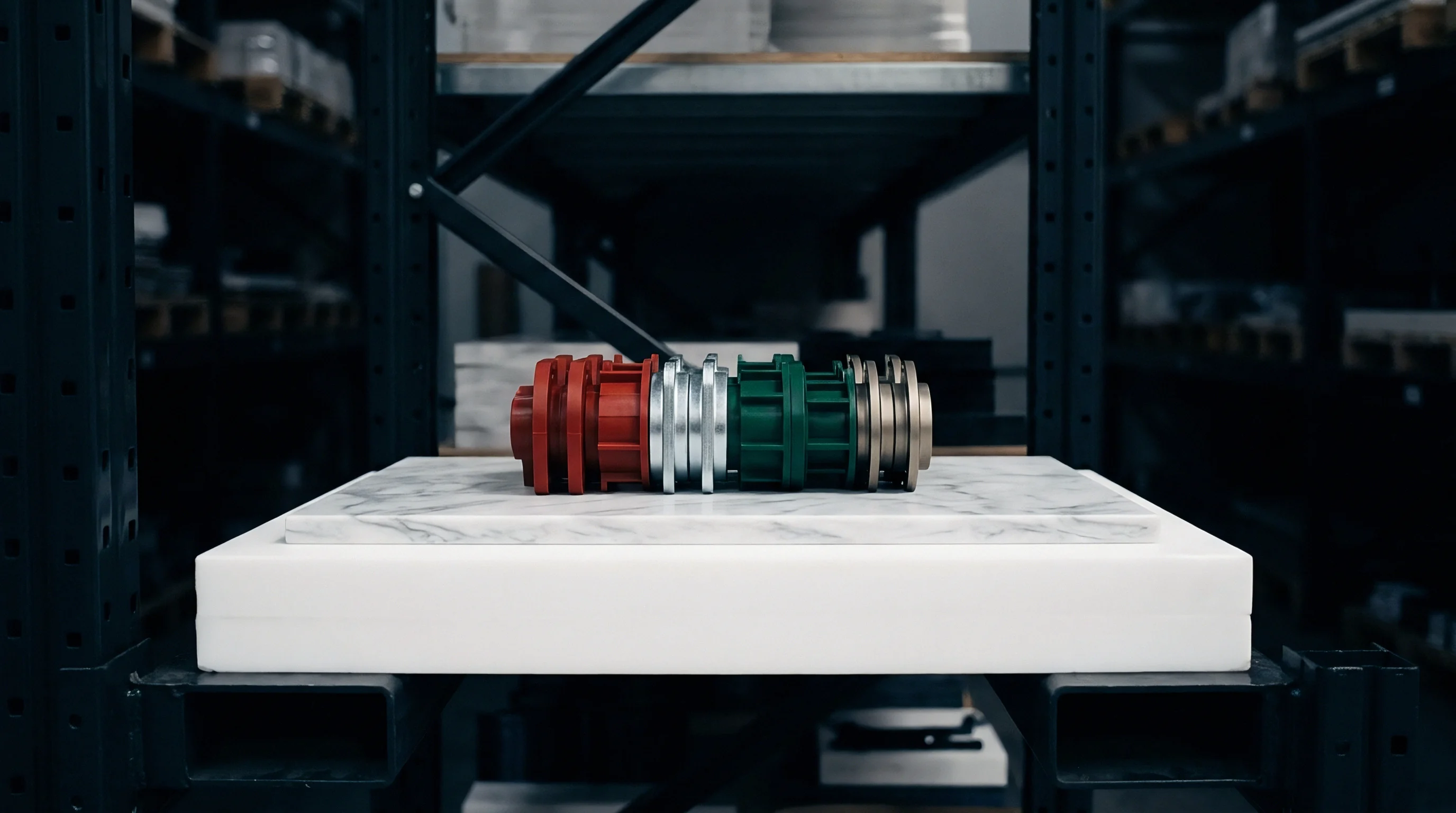
Grit
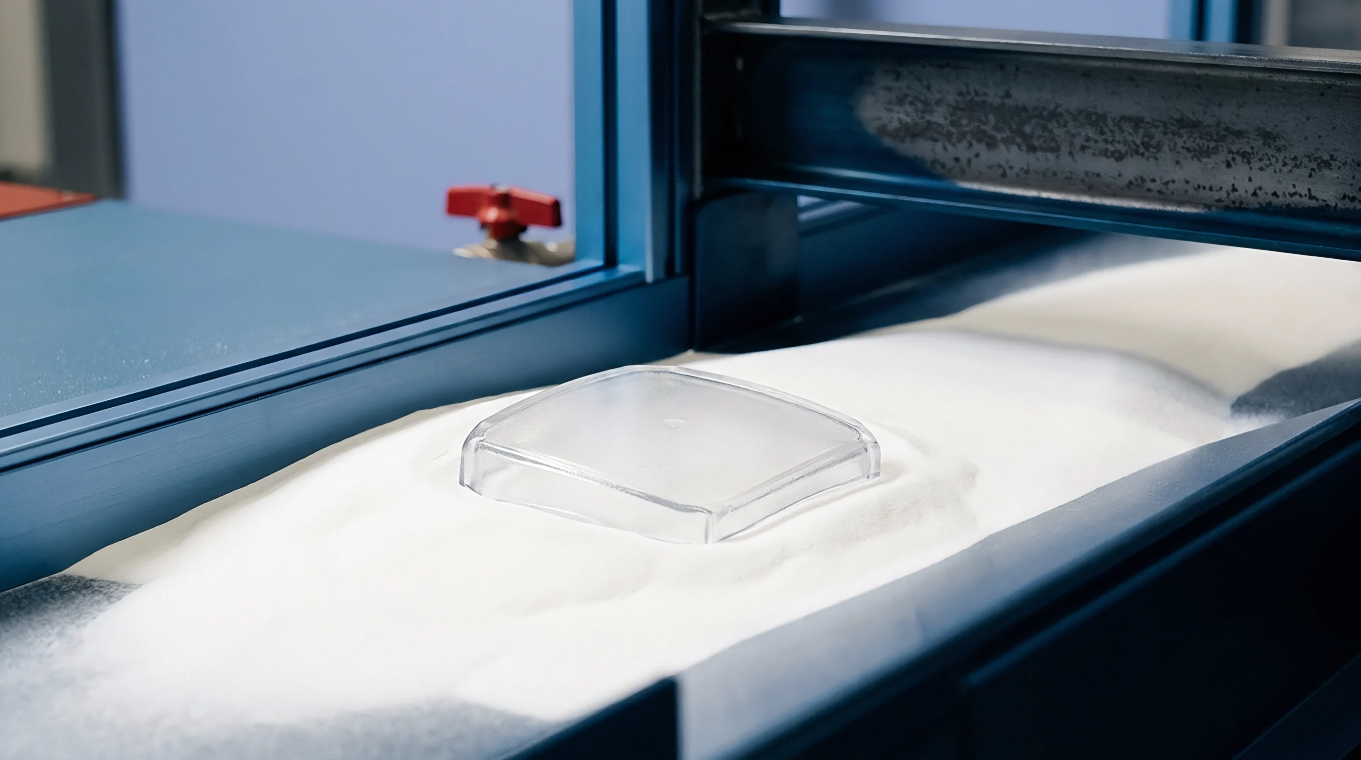
Abrasive particulate suspended within polymer fluids exerts high kinetic energy against channel walls during injection. High filler loadings, particularly glass fiber percentages exceeding forty percent by weight or ceramic powder charges above fifty percent by volume, turn the polymer melt into a dense abrasive slurry. Flow velocity peaks inside the narrowest region of the tool feed system.
As the fluid enters the gate aperture, localized acceleration increases individual particle momentum, establishing micro-cutting and micro-ploughing modes against the insert steel.
Tooling geometry dictates velocity. In sub-millimeter gate inserts produced via powder metallurgy, channel dimensions restrict fluid passage, elevating wall shear rates beyond fifty thousand reciprocal seconds. Soft metal binder phases suffer preferential loss, leaving hard carbide grains exposed to drag forces.
Hard particles scour soft metal. Once binder support drops below a critical threshold, fluid momentum dislodges intact carbide grains, producing accelerated surface degradation.

Kinetic Particle Dynamics in Micro Channels
Inclusions moving through sub-millimeter gate openings experience acceleration reaching several hundred meters per second. Particle momentum depends on particle radius, density, and local fluid velocity. At high concentration, mechanical collisions between particles redistribute solid phases across the velocity profile, concentrating sharp mineral edges along channel boundaries.
Impingement angles within diverging or converging gate lands dictate the dominant wear regime. Shallow impact angles below thirty degrees induce micro-cutting, where angular filler tips shear microscopic ribbons of metallic matrix material. Near ninety degrees, plastic deformation and micro-fatigue cracking dominate, shattering brittle phases.
Powder metallurgy gates must resist both mechanisms through balanced grain structure and high fracture toughness.
Hardness Ratios and Impact Mechanics
Solid phase constituents exceeding twelve hundred Vickers severely scour metallic surfaces. The relative hardness ratio between abrasive particle and insert wall controls abrasive penetration depth. When the abrasive hardness exceeds matrix hardness by a factor of 1.2, surface wear transitions from mild polishing to severe micro-abrasion.
| Insert Grade | Hardness (HV) | Thermal Conductivity (W/m K) | Fracture Toughness (MPa m0.5) | Relative Wear Index |
|---|---|---|---|---|
| WC-6Co (Submicron) | 1850 | 85.0 | 9.5 | 1.00 |
| WC-10Co (Fine) | 1600 | 100.0 | 11.8 | 1.45 |
| CPM 10V Tool Steel | 820 | 21.5 | 20.0 | 4.20 |
| Vanadis 8 PM Steel | 880 | 24.0 | 19.0 | 3.80 |
Coarser abrasive fillers demand harder binder matrices to withstand particle impingement at narrow constriction channels.

Rheology
Non-Newtonian fluid behaviors during high-velocity mould filling dictate local velocity distributions near walls. Highly filled thermoplastics exhibit pronounced shear-thinning characteristics described by Cross-WVF or Carreau-Yasuda viscosity formulations. At extreme shear rates encountered within gate lands, fluid viscosity drops sharply, concentrating deformation within a thin fluid boundary layer adjacent to the insert surface.
Cold walls raise shear stress. When hot molten suspension contacts a colder tool wall, rapid thermal conduction generates a steep temperature gradient across the boundary layer. Viscosity within this chilled boundary layer increases by orders of magnitude compared to the molten core flow, creating intense wall shear stress that transfers kinetic energy from the core directly onto the tool surface.

Shear Rate Gradients and Particle Migration
Velocity profiles across a narrow constriction force solid inclusions away from centerlines. Shear-induced particle migration causes suspended solids to migrate from regions of high shear rate at the insert wall toward lower shear rate regions in the core flow. The rate of migration scales quadratically with particle radius relative to channel gap height.
In ultra-thin gate inserts, particle migration competes directly with transit time. At injection speeds exceeding two hundred millimeters per second, residence time inside the gate land spans less than one millisecond, preventing particles from migrating away from the wall. Heavy particle packing persists at the wall boundary, maintaining high contact frequency between filler particulates and the metallic matrix.
Viscous Dissipation at Micro Constrictions
Mechanical energy converts rapidly into internal thermal energy inside narrow gate apertures. Viscous heating elevates localized fluid temperatures by twenty to fifty degrees Celsius during peak injection pressure. Viscous heat alters local velocity.
Temperature rises suppress boundary layer viscosity, reducing wall shear stress while increasing particle velocity at the immediate interface. Predicting wear rates under non-isothermal conditions requires coupling local wall temperature rises directly to matrix yield strength and fluid drag forces.
- Cohesive binder fatigue leads to binder leaching under continuous hydrodynamic shear stresses.
- Particle ploughing impact creates micro-grooves along the entrance edge of the gate insert.
- Thermal shock cracking initiates microscopic fissures across brittle tungsten carbide grains.
- Micro cavitation erosion strips matrix material near sharp geometry transitions inside the channel.
Resin formulators claim that filler orientation effects naturally shield gate surfaces from direct impact during steady high-speed injection.
Thermal
Temperature differentials between hot polymer suspensions and chilled mold walls create steep internal boundary layer variations. Melt entering the tool at three hundred degrees Celsius strikes insert steel maintained at one hundred degrees Celsius, initiating rapid conductive heat transfer. The resulting thermal boundary layer modifies both fluid viscosity and the mechanical response of the insert matrix.
Thermal gradient shapes matrix stress. Cyclic heating and cooling during each injection cycle induce transient compressive and tensile stress fields within the insert skin layer. Thermal expansion mismatch between hard carbide particles and ductile cobalt binders generates intergranular micro-stresses that lower fatigue thresholds.
Are Microcracks Induced by Rapid Surface Heat Fluctuation?
Cyclic contact with molten resin raises surface temperature within milliseconds before rapid mold cooling restores ambient baseline. Microcracks propagate under cyclic thermal shock. High thermal conductivity in tungsten carbide insert grades mitigates peak surface temperatures by dissipating heat into the surrounding mold cavity steel.
Tool steels possessing lower thermal conductivity accumulate localized heat, elevating surface temperatures into regimes where binder mechanical properties decay. Selecting powder metallurgy grades with optimized thermal diffusivity limits micro-crack initiation and prevents premature surface spalling during extended production runs.
Injection molding at 340 degrees Celsius melt temperature against a 120 degrees Celsius tool wall creates a transient thermal skin stress exceeding 450 megapascals in tungsten carbide gate inserts.
Transient Temperature Fields in Cold Tooling
Conduction models incorporate time-dependent boundary conditions to capture instantaneous freeze-layer boundaries. Polymer solidification at the insert wall reduces the effective hydraulic diameter of the gate, further accelerating core flow velocity and increasing shear forces along the liquid-solid frozen boundary.
Hydrodynamic forces act directly on the thin frozen skin layer. If wall shear stress exceeds the mechanical shear strength of the frozen polymer, the skin strips away, bringing high-velocity core slurry into direct contact with bare insert metal. Non-isothermal wear models incorporate this dynamic freeze-thaw transition to accurately calculate wear rates across the entire injection stroke.
Whether localized micro-melting of the cobalt binder during transient thermal peaks contributes more to grain dislodgement than hydrodynamic shear stress remains unquantified.


Erosion
Material loss models combine hydrodynamic wall shear stress with solid phase kinetic penetration energy. Standard room-temperature dry erosion models fail when applied to non-isothermal polymer slurry flows due to fluid drag damping and thermal softening of metallic binders. Modified formulations weight particle kinetic energy by local temperature-dependent matrix yield strength and fluid dynamic viscosity.
Volumetric erosion rates scale non-linearly with flow velocity. Increasing gate velocity from fifteen to thirty meters per second quadruples total material loss rate in tungsten carbide gate inserts. Gate geometry governs pressure drop.
Wear modeling must integrate fluid pressure drop variations to accurately project gate land dimensional growth over time.
Modified Wear Rate Formulation for Non Isothermal Suspensions
Predictive algorithms scale mass loss against kinetic energy flux and temperature-dependent binder yield parameters. Equation formulation integrates local wall shear stress, fluid temperature, solid fraction concentration, particle size distribution, and insert micro-hardness.
The volumetric material loss rate per unit area scales according to the equation:
W = K (density_p)^a (v_w)^b (C_v)^c (H_m / H_p)^d exp(-E_a / (R T_w))
where K represents empirical material calibration constant, density_p represents particle mass density, v_w represents local wall fluid velocity, C_v represents volume fraction of abrasive filler, H_m represents insert matrix hardness at temperature T_w, H_p represents filler particle hardness, E_a represents thermal activation energy of binder softening, R represents ideal gas constant, and T_w represents instantaneous interface temperature. Exponents a, b, c, and d are empirically calibrated exponents derived from non-isothermal slit-die wear experiments.
| Gate Velocity (m/s) | Melt Temp (°C) | Wall Shear Stress (kPa) | Calculated Wear Rate (um/10k shots) | Predicted Insert Life (Shots) |
|---|---|---|---|---|
| 15 | 290 | 120 | 0.12 | 830,000 |
| 25 | 310 | 210 | 0.48 | 208,000 |
| 35 | 330 | 340 | 1.65 | 60,000 |
| 45 | 350 | 510 | 4.20 | 23,000 |

Parametric Sensitivity and Model Calibration
Empirical curve fitting relies on pin-on-disc abrasive testing combined with pressure-drop monitoring across calibrated test gates. Sensitivity analysis demonstrates that fluid velocity exponent b ranges between 2.2 and 2.8, indicating extreme sensitivity to localized gate constriction geometry.
Tooling agreements referencing ISO 20753 require gate land dimensional tolerance retention within plus or minus ten micrometers throughout the initial two hundred thousand production cycles.
Cobalt depletion reduces insert life. Temperature exponent adjustments account for binder softening above two hundred degrees Celsius, where cobalt yield strength drops by over thirty percent compared to ambient baseline values.
Underestimating boundary shear degradation leads to unexpected gate geometry expansion, excessive part flash, and unbudgeted mold removal.

Matrix
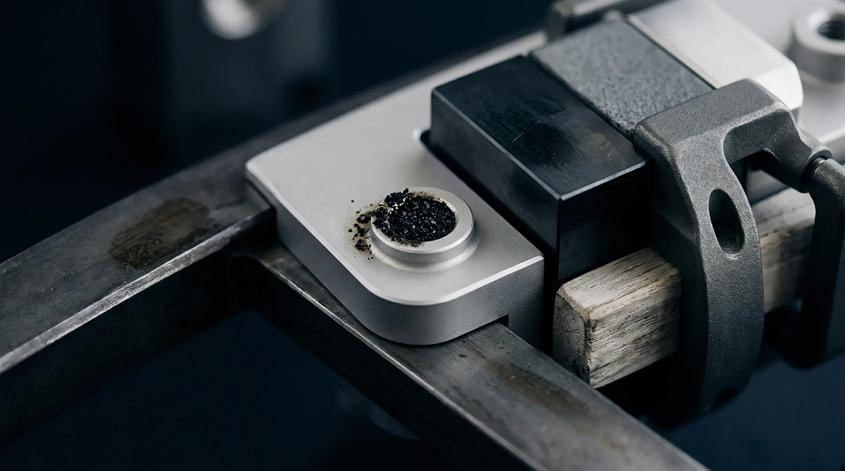
Powder metallurgy compositions utilize fine-grain hard phases embedded within ductile metallic binders to withstand complex stresses. Tungsten carbide grains provide primary resistance against micro-cutting by abrasive mineral fillers. Matrix binder material, typically cobalt or nickel, absorbs impact energy and prevents catastrophic brittle fracture during mechanical loading.
Grain size distribution dictates mechanical performance. Submicron tungsten carbide grains under 0.8 micrometers decrease mean binder path length, reducing the volume of exposed cobalt susceptible to preferential erosion. Cobalt binder wash precedes grain loss.
Compacting powder blends under hot isostatic pressing achieves near-theoretical density, eliminating internal microporosity that accelerates wear initiation.

Cobalt Depletion and Micro Grain Dislodgement
Leaching mechanisms lower binder cohesion between tungsten carbide grains, exposing individual particles to hydrodynamic drag forces. Corrosive additives within certain resin formulations, such as flame retardants or coupling agents, attack metallic binders chemically while mechanical erosion strips softened reaction products.
Synergistic mechanical and chemical degradation accelerates material loss beyond pure abrasive projections. Selecting nickel-chromium alloy binders enhances chemical resistance, maintaining structural support around carbide grains under corrosive melt environments.
Submicron tungsten carbide grains with six percent cobalt binder provide higher wear resistance than coarse-grain grades in abrasive glass-filled polymer processing.

Surface Preparation and EDM Recast Elimination
Thermal cutting methods leave altered metallurgical surface layers containing micro-voids and tensile residual stresses. Electro-discharge machining creates a brittle recast layer containing micro-fissures that act as stress concentration sites during thermal cycling.
- Prepare the powder metallurgy blank using hot isostatic pressing at thirteen hundred degrees Celsius.
- Machine the gate aperture profile using wire electro-discharge machining with fine wire settings.
- Remove the recast layer through chemical etching and ultrasonic diamond slurry polishing.
- Verify initial orifice geometry using optical coordinate measuring equipment under high magnification.
- Install the insert into the mold base using controlled press-fit interference fits.
Inserting DIN ISO 286 grade tolerances into the tooling purchase agreement forces toolmakers to replace eroded PM inserts once orifice growth exceeds fifteen micrometers.

Yield
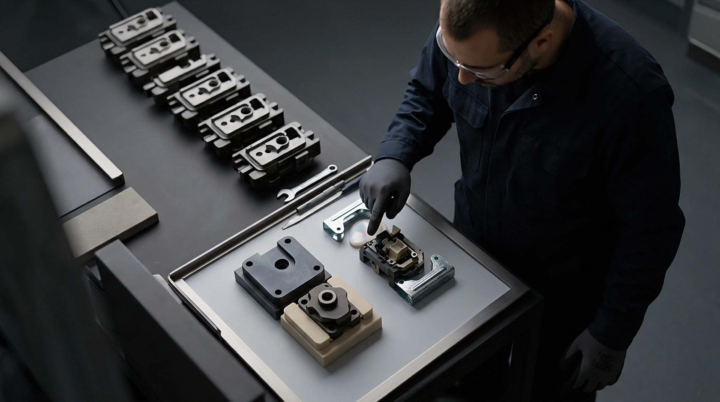
Tooling longevity determines part piece pricing across production volumes exceeding five hundred thousand shots. Gate land wear increases hydraulic cross-section, reducing injection pressure drop and altering cavity filling dynamics. Steel costs escalate rapidly.
Uncontrolled gate growth causes part weight drift, sink marks, and parting line flash that compromise dimensional compliance.
Orifice enlargement alters part weight. Tracking cavity pressure traces across production shifts provides indirect verification of gate geometry drift. Wear changes cavity pressure limits.
Upfront investment in high-grade powder metallurgy inserts lowers amortized tooling costs per part over the complete production life of the tool.
Economic Break Even and Cavitation Refurbishment
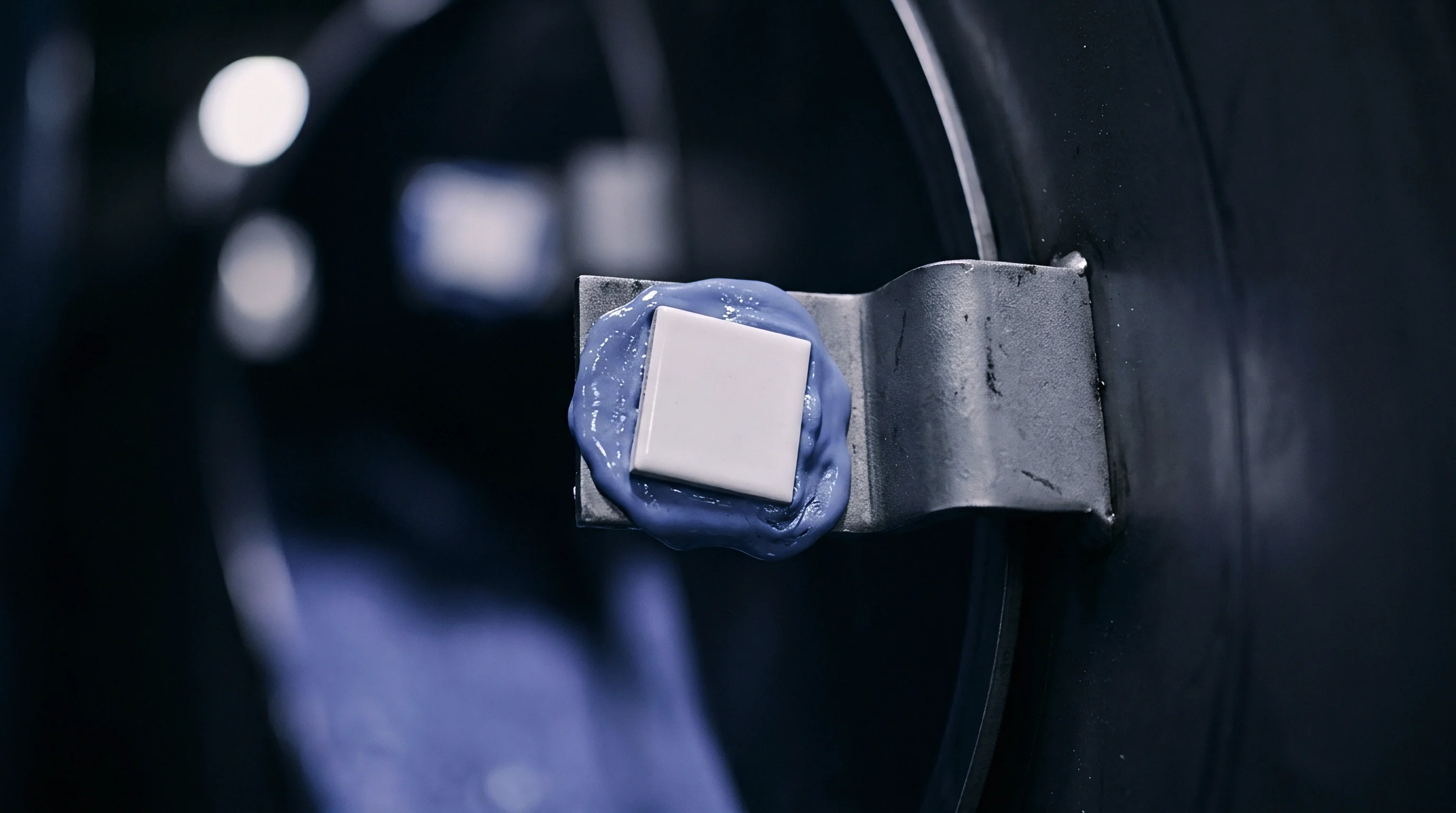
Insert replacement schedules balance tool downtime costs against scrap rates caused by gate land enlargement. Standard tool steel inserts require frequent refurbishing or replacement when processing forty percent glass-filled resins, accumulating significant maintenance downtime.
| Insert Option | Initial Tooling Cost (USD) | Insert Replacements Required | Maintenance Downtime Cost (USD) | Amortized Cost per Part (USD) |
|---|---|---|---|---|
| Hardened H13 Steel | 1,200 | 12 | 18,000 | 0.0192 |
| TiAlN Coated CPM 10V | 2,800 | 4 | 6,000 | 0.0088 |
| WC-6Co PM Insert | 4,500 | 0 | 0 | 0.0045 |
Gate Geometry Drift and Flash Formation
Dimensional expansion of gate openings elevates cavity pressure limits, altering packing efficiency and dimensional stability. Tooling quotes assume stable dimensions. When gate size increases by twenty percent, shear heating drops, increasing fluid viscosity inside the cavity and inducing sink marks in thick part sections.
Tooling amortisation costs drop below two cents per part when powder metallurgy insert life extends beyond eight hundred thousand shots.
- Gate growth monitoring tracks cavity pressure drop variations across consecutive production shifts.
- Part weight tracking detects subtle volume changes caused by gate orifice enlargement.
- Visual flash inspection identifies edge breakdown along the parting line of the gate insert.
- Insert replacement criteria specifies maximal allowable dimensions before part rejection occurs.
Correct alignment between insert hard-phase grain size and polymer filler geometry stabilizes production windows across high-volume automotive moulding runs.