Micro Structured Tool Inset Thermal Contact Conductance Fundamentals
Micro-structured insets choke thermal conductance through trapped micro-cavity air and loose back-face pocket fit, demanding rigid clamping and high packing pressure.

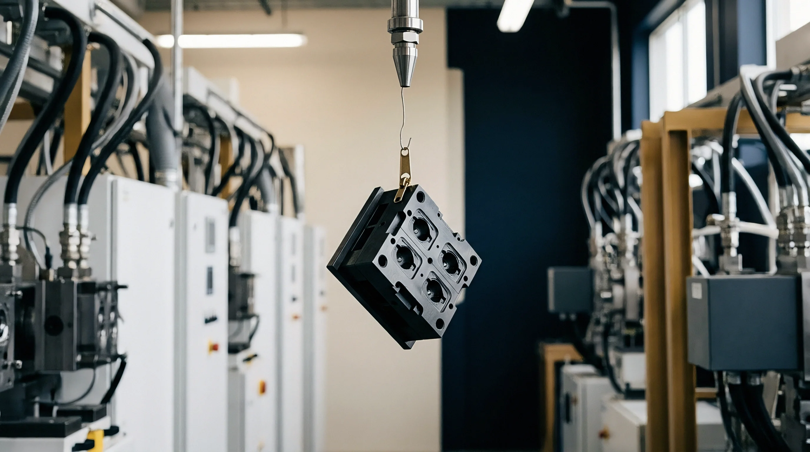
Texture
Cavity pressure records show a steep drop in heat flux the moment micro-scale features enter the tool steel. At an injection pressure of 85 MPa with an optical-grade polymethyl methacrylate melt at 240 degrees Celsius, a polished tool surface with an average roughness Ra of 0.02 micrometers produces a nominal thermal contact conductance of 2800 W/(m²·K). Etch a cross-hatch diffraction grating of 4-micrometer pitch and 1.8-micrometer depth into that same inset, and the apparent heat transfer coefficient plummets to 620 W/(m²·K) during the first forty milliseconds of cavity filling.
The melt touches only the crests of the tool relief. Trapped gas fills the troughs, creating a micro-scale thermal insulator precisely where heat removal governs feature replication.
Every tool drawing specifying micro-features carries this dual thermal barrier. The polymer cannot establish contiguous physical contact across the micro-machined profile until cavity pressure overcomes the combined resistance of melt surface tension, viscoelastic shear thinning, and adiabatic gas compression. Molten polycarbonate entering an array of micro-pillars at 290 degrees Celsius exhibits a meniscus radius determined by the Laplace equation.
If cavity air cannot escape through permeable tool steel or dedicated micro-vents of 0.002-millimeter land clearance, the air pocket compresses under polytropic heating. Local thermal contact conductance drops by up to eighty percent relative to bulk flat-wall tooling. Heat stays trapped in the polymer skin.
Trapped cavity air at 60 MPa packing pressure reduces interface heat flux by seventy-four percent compared to a ground tool face.
Solidification mechanics alter immediately. Under conventional tool contact conditions, a frozen skin layer forms within twelve milliseconds, establishing a conductive thermal bridge across the tool steel. On a micro-structured inset, the delayed physical contact keeps the polymer skin above the glass transition temperature during the dynamic filling phase.
Tool designers exploit this delay to replicate high aspect ratio structures. The delay carries a severe penalty during cooling. The local heat sink capacity degrades, prolonging the required dwell time before part ejection.

Asperity Constriction across Micro-Groove Boundaries
Microscopic contact occurs across discrete summits rather than continuous planes. When the polymer front advances across micro-grooved tool inserts, constriction thermal resistance arises inside the metallic summits themselves. Heat flux lines converge through narrow metal plateaus before reaching the bulk substrate, throttling the conduction pathway.
Surface roughness profiles dictate the real area fraction of contact. Profilometer scans on micro-milled tool steels reveal that peak-to-valley heights Rt fluctuate across individual machining tracks by plus or minus 0.35 micrometers on a nominal 2.0-micrometer feature depth. When molten cyclic olefin copolymer contacts these peaks, microscopic air gaps occupy between forty and seventy percent of the total projected interface area during the filling phase.
Thermal conductivity of the trapped gas mixture measures approximately 0.031 W/(m·K), whereas the tool steel conducts between 24 and 32 W/(m·K). Conduction across the interface behaves as two parallel thermal impedances, dominated completely by the low conductance of the gas gaps.
Steel hardness dictates summit preservation under repetitive hydraulic loading. Hardened martensitic stainless steels, specifically DIN 1.2083 heat-treated to 52 HRC, resist plastic deformation of micro-rib crests under cyclic clamping. Softer alloys undergo micro-yielding.
Summit flattening increases apparent contact area over five thousand shots, shifting local cooling rates unpredictably across production campaigns.
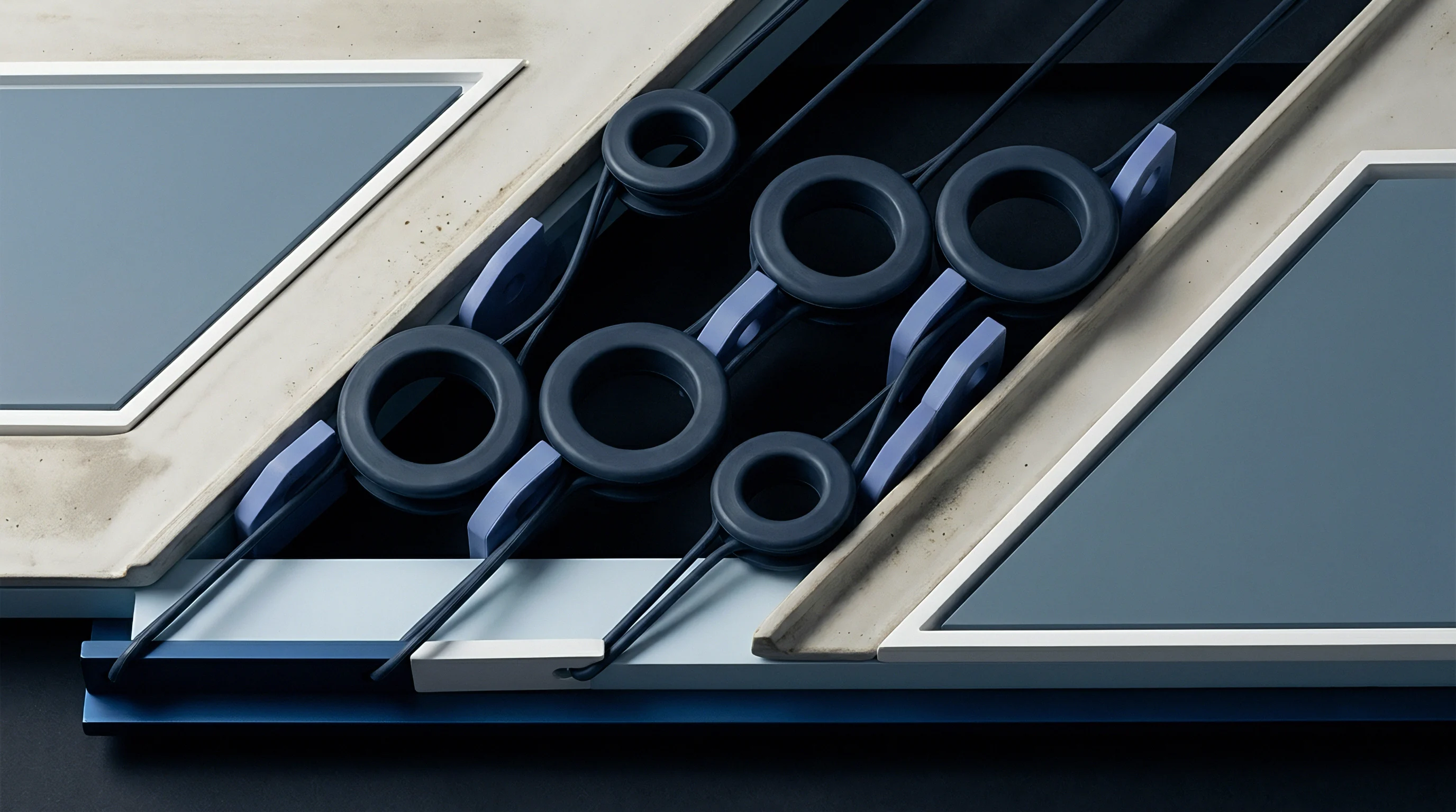
Interface Topography and Contact Impedance
Topographical parameters govern thermal contact conductance across every micro-machined inset geometry. The table below compiles contact conductance metrics evaluated across typical micro-structured injection tool configurations under steady-state packing conditions.
| Inset Substrate Material | Feature Morphology | Feature Depth (µm) | Real Contact Ratio | Thermal Conductance (W/(m²·K)) |
|---|---|---|---|---|
| DIN 1.2083 (AISI 420 ESR) | Linear Prisms (90°) | 12.5 | 0.48 | 840 |
| DIN 1.2343 (AISI H11) | Hexagonal Pillars | 5.0 | 0.62 | 1250 |
| Nickel Electroform | Diffractive Grating | 1.2 | 0.79 | 2100 |
| Beryllium Copper (C17200) | Micro-Fresnel Rings | 8.0 | 0.55 | 3400 |
| Tungsten Carbide Inset | Cross-Hatch Grooves | 3.5 | 0.71 | 1680 |
Interface conductance values scale with the real contact area ratio. Tool materials possessing superior bulk thermal conductivity, such as copper-beryllium alloys, compensate for reduced contact ratios by accelerating heat dissipation through the summits. Steel inserts maintain lower bulk conductance, intensifying the thermal bottleneck created by micro-patterning.
Mould builders ignoring micro-scale contact resistance produce cavities that fail dimensional sign-off through severe differential shrinkage and persistent sink marks across the structured zone.
Shim
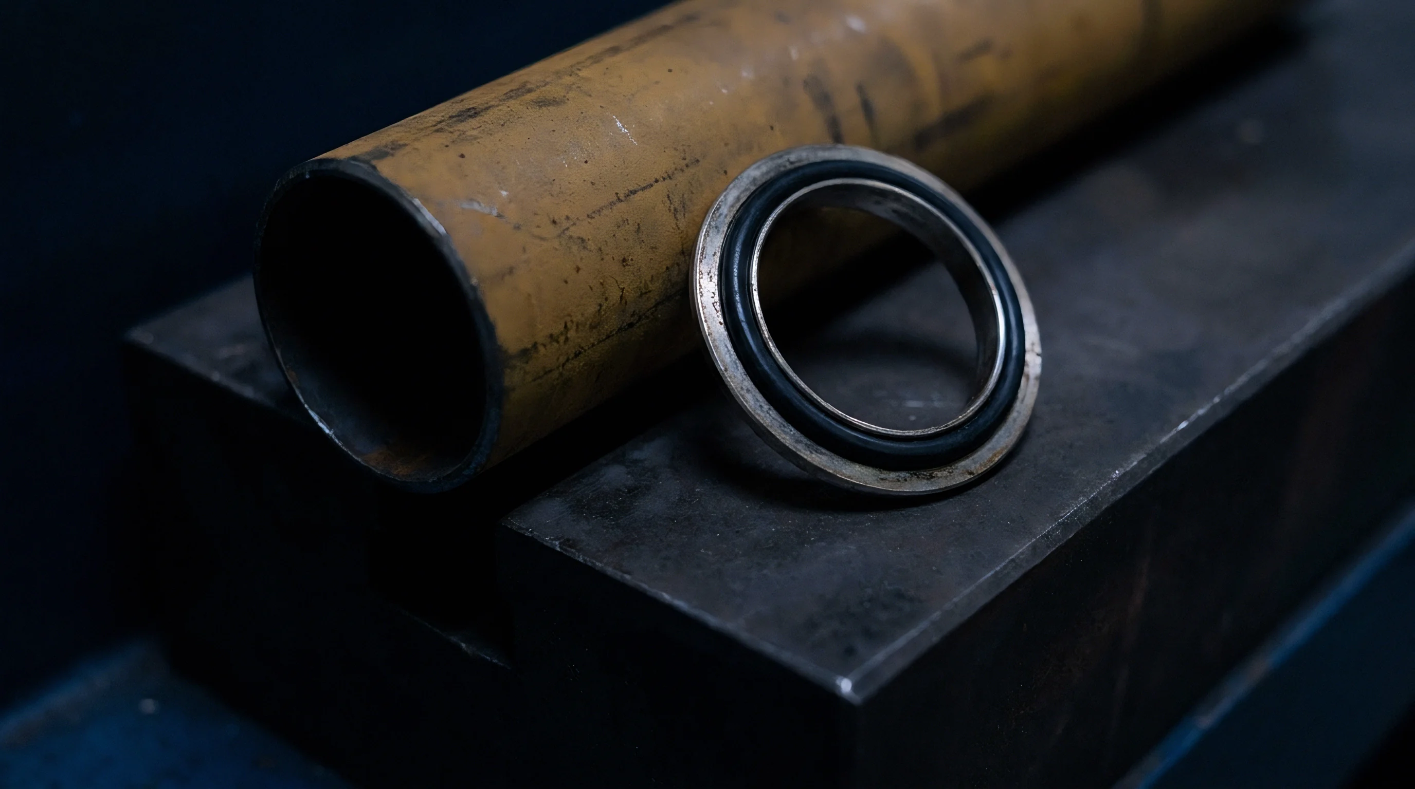
Back-face seating determines whether a tool inset functions or overheats. Toolmakers frequently focus on the micro-cavity face while treating the rear pocket interface as a secondary consideration. A precision micro-structured inset mounted into a hardened cavity pocket introduces a second contact resistance.
This structural junction acts in series with the polymer-steel cavity interface. If the tool room mills the pocket floor with a standard end mill, leaving a surface roughness Ra of 1.6 micrometers, the thermal contact conductance between the inset back-face and the bolster plate drops to roughly 1800 W/(m²·K) under standard mechanical clamping.
Stack-up resistance stalls heat evacuation into cooling lines. Cooling channels drilled into the main tool block sit ten to fifteen millimeters behind the pocket floor. Heat flowing from the polymer must cross the micro-cavity interface, traverse the inset thickness, bridge the pocket floor junction, and pass through the mold base steel before entering the water channel.
A pocket floor lacking planarity generates a localized heat dam. The inset runs hot. Cycle time lengthens, and micro-feature ejection produces severe optical distortion.
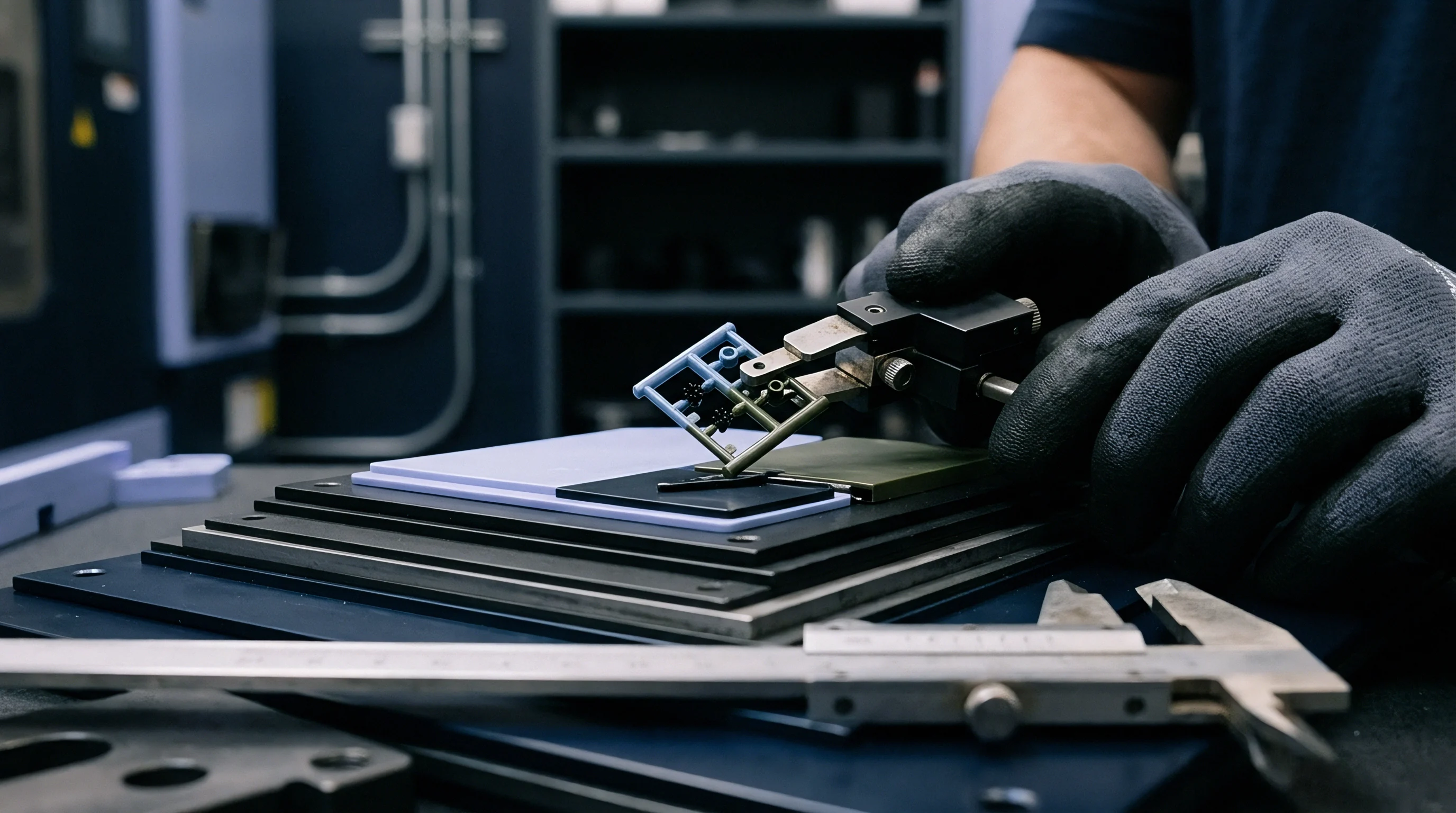
Preload control eliminates secondary boundary resistance. Precision shims, ground to tolerances within 0.002 millimeters under DIN EN ISO 1101, establish uniform mechanical contact across the entire mounting pocket. Tool rooms use hardened ground shims made of DIN 1.2842 tool steel to correct depth variances without introducing spongy compliance under cyclic injection tonnage.
Mechanical Clamping Force Distribution
Clamping torque applied to inset retention bolts directly governs back-face contact conductance. Retention screws tensioned unevenly induce minute bowing across thin insets. An inset bowed by four micrometers creates a central air gap of equivalent thickness against the pocket floor.
Air gaps behind tool inserts choke transient heat dissipation. Conduction across a four-micrometer dry air gap delivers a thermal conductance of merely 6500 W/(m²·K). While seemingly high compared to the plastic interface, this resistance layer exists continuously across the entire shot cycle, preventing the inset from shedding base heat between cycles.
Heat accumulation drives steady-state tool temperatures upward by twenty to forty degrees Celsius within fifty continuous press strokes.
Differential thermal expansion compounds seating errors. Beryllium copper insets installed within P20 tool steel bolsters expand at 17.5 microstrain per Kelvin, compared to 12.0 microstrain per Kelvin for the surrounding steel. Without precise edge clearances of 0.015 millimeters per side, the inset binds against the pocket walls, buckling away from the base floor and severing back-face contact.
A tool room document governs inset thickness tolerance to plus zero and minus five micrometers under DIN EN ISO 1101 to prevent thermal pocket isolation.
Mounting Interface Preparation Steps
Achieving stable thermal coupling across the inset seat demands disciplined toolroom machining routines.
- Grinding the pocket floor establishes planar contact across ninety percent of the seat area, eliminating machining cusps from ball-nose milling cutters.
- Lapping the inset back-face produces a surface finish Ra below 0.1 micrometers, maximizing metallic summit micro-contacts under bolt tension.
- Applying metallic interface foils bridges microscopic air voids between the pocket base and the hardened inset body. A five-micrometer soft copper or silver-plated foil deforms plastically under assembly torque, multiplying thermal conductance across the dry joint by a factor of three.
- Torquing retention bolts symmetrically in twenty-percent increments avoids localized elastic deflection of the micro-structured faceplate.
Tool procurement contracts referencing DIN 16742 TG3 specify that inset pocket depth variances exceeding 0.005 millimeters void the toolmaker dimensional guarantee across optical micro-arrays.
Solidification
Phase transitions in semi-crystalline and amorphous polymers respond directly to micro-scale boundary heat fluxes. As molten polymer enters the micro-cavity, the instantaneous heat extraction rate dictates whether molecular chains relax into micro-grooves or freeze prematurely into a vitrified crust. For polypropylene processing at 210 degrees Celsius against a tool wall maintained at 40 degrees Celsius, local cooling rates inside micro-features reach 800 Kelvin per second during initial wall impact.
Crystalline morphology shifts with thermal contact conductance gradients. Fast heat extraction yields a dense, highly oriented, non-spherulitic skin layer displaying high shear stresses and elevated optical birefringence. Slow heat extraction, caused by low contact conductance over micro-groove voids, promotes spherulitic nucleation.
Spherulites scattering transmitted light degrade diffraction gratings and light guide plates. Thermal boundary control becomes an optical property control mechanism.
Transient conductance variations generate differential shrinkage across micro-patterns. Feature peaks cool through two-dimensional heat dissipation pathways, while feature valleys experience restricted one-dimensional conduction into the bulk tool. Valley sections remain molten for twelve to eighteen milliseconds longer than peak zones.
Polymer shrinkage pulls the cooling plastic away from vertical feature sidewalls, dropping lateral contact conductance to zero and terminating direct conduction.

Does Contact Pressure Alter Apparent Resistance?
Packing pressure drives molten polymer deeper into tool micro-structures, steadily increasing the true contact area. Cavity pressure sensor data demonstrates a non-linear relationship between hydraulic line pressure and interface thermal conductance.
Experimental injection data establishes distinct conductance regimes during a single machine stroke. During the filling phase, when cavity pressure remains below 15 MPa, thermal contact conductance hovers between 350 and 700 W/(m²·K). As the machine initiates switchover and reaches a packing plateau of 65 MPa, the polymer deforms viscoelastically around micro-asperities.
Real contact area expands from thirty percent to eighty-two percent of the projected plane. Conductance surges to 2600 W/(m²·K). The interface resistance drops by seventy-three percent in twenty-five milliseconds.
Holding pressure decay reverses this thermal coupling. When the gate freezes, cavity pressure decays as the core polymer contracts. At pressures below 20 MPa, volumetric thermal shrinkage breaks mechanical contact between the plastic and micro-groove flanks.
Air or process off-gasses fill the resulting vacuum gap. Thermal contact conductance falls back to roughly 450 W/(m²·K), trapping residual heat within the part core and prolonging the cooling phase.

Conductance Dynamics across Process Phases
Thermal contact conductance evolves through specific stages during the injection cycle. The breakdown below details the transition points across a standard micro-moulding cycle operating with high-heat amorphous polycarbonate.
| Cycle Phase | Duration (ms) | Cavity Pressure (MPa) | Contact Conductance (W/(m²·K)) | Dominant Heat Transfer Mode |
|---|---|---|---|---|
| Flow Front Contact | 10 – 45 | 2 – 12 | 380 – 650 | Constriction Conduction Across Crests |
| Dynamic Packing | 45 – 250 | 45 – 90 | 1800 – 3100 | Viscoelastic Creep Conduction |
| Thermal Holding | 250 – 1200 | 30 – 60 | 1200 – 1900 | Bulk Conduction Across Compressed Boundary |
| Gate Freeze And Relaxation | 1200 – 2800 | 8 – 25 | 500 – 850 | Gas-Filled Micro-Gap Conduction |
| Part Cooling And Ejection | 2800 – 5500 | 0 – 2 | 180 – 320 | Radiation And Micro-Gap Air Conduction |
Pressure profiles directly dictate cooling kinetics. Raising packing pressure from 40 MPa to 80 MPa cuts total part cooling time by twenty-eight percent because the elevated pressure sustains high thermal contact conductance across the micro-featured boundary during the initial hold phase.
A designer estimating cycle times based on steady-state conduction values will miss actual cycle durations by several seconds. Conduction across micro-features is an inherently transient phenomenon governed by local cavity pressures and polymer rheology.
Whether viscoelastic recovery of the polymer skin creates microscopic air gaps before core crystallization completes remains an open research question across thin-wall precision tooling.


Window
Stable moulding across micro-structured surfaces demands precise control over the hydraulic process envelope. If the injection velocity drifts by five percent, the melt front freezes before packing pressure reaches the micro-features, causing incomplete replication. If the barrel temperature climbs by six degrees Celsius, the polymer degrades, outgassing volatile components that form an insulating chemical film over the micro-grooves.
Process stability requires balancing melt temperature, tool temperature, injection rate, and holding pressure.
Variotherm processing alters the thermal contact conductance window dramatically. In standard isothermal injection, the tool operates at a fixed temperature, typically twenty to forty degrees below the polymer heat deflection point. In variotherm systems, external induction coils, ceramic heating elements, or high-pressure steam circuits heat the micro-structured inset above the polymer glass transition temperature immediately before injection.
Polycarbonate melt touches steel heated to 155 degrees Celsius. The polymer remains fully fluid, eliminating premature skin freeze.
Thermal contact resistance during variotherm filling falls to negligible levels. Because the melt does not freeze against the hot tool, the polymer flows into micro-grooves under minimal flow resistance, achieving over ninety-five percent feature height replication at holding pressures below 35 MPa. Once filling finishes, high-flow water circuits drop the inset temperature to 80 degrees Celsius within three seconds.
Dynamic variotherm cycles consume additional energy and cycle time, adding between four and twelve seconds to every press stroke.
Is Microstructure Replication Bound to Local Cooling?
Dimensional fidelity of micro-optical features correlates directly with local heat flux uniformity. Non-uniform thermal contact conductance across an array of micro-prisms induces local warpage and refractive index variations.
Testing protocols established under DIN 16742 measure dimensional variations across injection-moulded components. On an optical diffuser carrying two million micro-lenses across a fifty-millimeter plate, cooling rate differentials of fifteen Kelvin per second across the part face distort lens focal lengths by up to twelve percent. The outer lenses cool through two-sided heat conduction, while the central lenses retain heat due to lower contact conductance over compressed air pockets.
The moulder must adjust coolant flow rates through independent baffle circuits to balance these local thermal gradients.
Polymer choice constrains the processing window. High-flow grades displaying a melt flow index exceeding thirty grams per ten minutes penetrate micro-patterns readily, but sacrifice impact strength and mechanical creep resistance. Tougher optical grades with lower flow indices require elevated packing pressures and higher tool temperatures, narrowing the processing window to a narrow range of machine setpoints.
A temperature drift of two degrees Celsius across the inset face alters micro-prism height replication by seven percent under steady hydraulic packing.
Critical Process Setup Constraints
Maintaining micro-feature stability requires systematic press parameter control.
- Melt injection velocity must stay above 180 millimeters per second to prevent frozen skin formation before the cavity reaches volumetric fill.
- Switchover positioning calibrated through cavity pressure transducers ensures packing pressure transfers instantly when the melt reaches ninety-eight percent cavity volume.
- Coolant flow rates operated at Reynolds numbers above 10,000 maintain turbulent heat extraction within cooling passages directly adjacent to the micro-structured inset pocket.
- Clamping force calibration prevents micro-breathing of parting line vents, which would alter local cavity venting efficiency and trapped air insulation.
A supplier will typically claim that sub-micron surface variances result from batch-to-batch polymer raw material instability rather than unchecked temperature drift across the tool inset.

Recovery
Tooling capital spent on micro-structured insets must be recovered across production part volumes. A four-cavity optical tool requiring diamond-machined or femtosecond laser-textured insets carries an upfront fabrication charge between 28,000 and 65,000 euros. Micro-machined insets do not last indefinitely.
Abrasive wear, polymer shear stress, and thermal cycling degrade micro-features over time, requiring planned inset refurbishments or replacements.
Part piece-price calculations must account for inset longevity. Processing unfilled optical polymers such as polymethyl methacrylate or cyclic olefin copolymers allows nickel-plated or hardened steel insets to sustain between 150,000 and 300,000 shots before edge rounding degrades optical performance. Introduce thirty percent glass-fiber reinforcement or mineral flame retardants, and inset service life drops below 20,000 cycles.
A micro-milled inset costing 8,000 euros amortised across 20,000 parts adds forty euro cents to every moulded unit, completely overshadowing raw material and machine-hour costs.
Tooling economics demand modular inset architectures. Machining micro-structures directly into the main cavity bolster represents a severe commercial risk. If a single micro-rib chips or experiences vent burn from diesel effect ignition, the entire mould block must be removed, annealed, welded, re-machined, and re-hardened.
Modular insets allow rapid bench swap-outs within twenty minutes, minimizing production downtime.

Worked Cost Model across Production Run Scenarios
Evaluating commercial viability requires comparing inset fabrication technologies against total production requirements. Consider a production run of 500,000 automotive optical sensor covers carrying micro-groove anti-reflective arrays, produced in an eight-cavity injection mould.
Assume an hourly press operating rate of 85 euros on a 150-tonne all-electric injection machine. Inset replacement costs depend entirely on the micro-machining method chosen during tool fabrication. Diamond micro-milling delivers optical surface finishes with Ra values below 0.005 micrometers, but each eight-cavity inset set costs 32,000 euros and achieves an operating life of 125,000 shots in optical polycarbonate.
Femtosecond laser texturing costs 14,000 euros per set, producing an Ra of 0.04 micrometers and sustaining 250,000 shots. Nickel electroformed shims cost 9,000 euros per set but require replacement every 60,000 cycles due to mechanical shear damage under 80 MPa packing pressures.
| Tool Inset Technology | Initial Inset Cost (€) | Useful Inset Life (Shots) | Replacement Sets Needed | Total Inset Spend (€) | Inset Cost Per Part (€) |
|---|---|---|---|---|---|
| Diamond Micro-Milling | 32,000 | 125,000 | 3 | 128,000 | 0.0320 |
| Femtosecond Laser Ablation | 14,000 | 250,000 | 1 | 28,000 | 0.0070 |
| Nickel Electroforming (LIGA) | 9,000 | 60,000 | 7 | 72,000 | 0.0180 |
| Silicon Wet Etched Insets | 18,000 | 40,000 | 11 | 216,000 | 0.0540 |
The arithmetic reveals that lowest initial tooling cost rarely yields lowest landed cost. While nickel electroforming presents an initial tooling quote seventy-two percent cheaper than diamond milling, its rapid mechanical wear requires seven production tool teardowns, driving total inset spend to 72,000 euros. Femtosecond laser ablation minimizes total capital allocation, provided the component optical specifications can tolerate its slightly higher surface roughness.
Tooling quotes must separate base mould base capital from consumable micro-structured inset packages. A procurement contract that fails to fix inset replacement pricing upfront leaves the buyer vulnerable to tooling price gouging once production begins.
A tool that runs cold preserves steel at the price of part clarity.