Optical Coherence Measurement Fundamentals for Deep Tooling Cavities
Optical coherence measurement uses broad-bandwidth infrared interference to capture deep cavity topographies without mechanical probe contact or lens clipping.
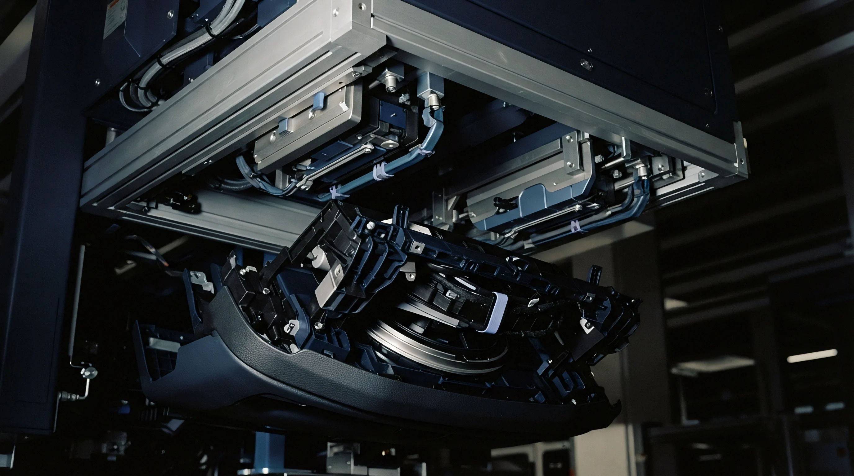

Beam
Low coherence light directed into a hardened steel cavity isolates surface reflections through optical path interference rather than geometric focal depth. Conventional laser triangulation and chromatic confocal sensors depend on high numerical aperture collection lenses to resolve vertical displacement. When an injection mould feature exhibits an aspect ratio exceeding five to one, physical sidewalls clip the illumination cone of confocal optics, extinguishing the return signal before photons reach the detector pinhole.
Low coherence interferometry splits broad-bandwidth infrared radiation between a reference arm and a sample arm, routing a quasi-collimated probe through high-aspect channels down to ten millimeters deep with beam diameters under thirty micrometers.
Coherence length governs vertical measurement resolution. A superluminescent diode emitting at a central wavelength of 1310 nanometers with a spectral bandwidth of 85 nanometers yields an axial coherence length of approximately nine micrometers in air. Photons reflected from the tool floor combine with the reference signal only when optical paths match within this narrow coherence envelope.
Mechanical clearance around deep ribs no longer limits depth discrimination. The instrument maps bottom-floor topography, spark-erosion textures, and micro-milling step marks without contacting polished cavity surfaces.
Coherent light backscattered from a tool floor reveals true cavity depth without mechanical contact from a stylus.
Axial resolution stays fixed. Lateral resolution depends on objective focal length, while axial resolution remains tied to source spectral bandwidth. Decoupling spatial focusing from depth resolution allows toolmakers to inspect narrow cooling channels and core pin bores that defeat focus-variation microscopes.
Optical coherence measurement tracks cavity topography through a single optical fiber probe integrated into machining centers or benchtop gantry stages. Steel reflects light directly.
Fresnel reflection at normal incidence on polished tool steel delivers roughly two to four percent of incident optical power back into the fiber core. This return fraction provides sufficient signal amplitude for high-speed spectral detection. The probe sweeps across the tool plane while the interferometer digitizes interferograms at line rates exceeding fifty kilohertz.


Interference
Spectral interferograms encode spatial distance through frequency-domain modulation. In a swept-source system, a narrow-linewidth laser sweeps rapidly across a broad infrared spectrum, illuminating the cavity while a photodiode monitors total reflected intensity. Heterodyne beat frequencies arise from optical path differences between the stationary reference mirror and reflective features inside the tooling pocket.
Fast Fourier transformation converts these recorded frequency ripples into depth-resolved reflectivity profiles, generating vertical scans without mechanical depth translation.

Spectral Dispersion Compensation in Tooling Cavities
Chromatic dispersion shifts phase relationships within broadband wavepackets as light traverses optical windows, focusing lenses, and air gaps inside deep cavities. Uncorrected dispersion broadens the point spread function, degrading axial sharpness from four micrometers to twenty micrometers over a six-millimeter travel range. Hardware compensation inserts matched glass blocks into the reference path, while numerical compensation applies quadratic and cubic phase corrections directly to the raw spectral data before Fourier transformation.
Swept laser sources operating near 1310 nanometers maintain three micrometer axial precision across an eight millimeter scanning range in hardened H13 tool steel.
Phase stability dictates repeatability across repeated scans. When shop-floor ambient temperatures drift by two degrees Celsius during an overnight tool qualification cycle, physical path lengths inside fiber conduits drift by several optical wavelengths. Balanced reference arms eliminate common-mode thermal noise, allowing sub-micrometer step-height determination on core inserts.
Tool steel absorbs heat.
| Architecture | Central Wavelength | A-Scan Rate | Axial Resolution | Usable Depth Range |
|---|---|---|---|---|
| Time-Domain Detection | 840 nm | 0.5 kHz to 2 kHz | 6.0 µm to 12.0 µm | 1.5 mm to 3.0 mm |
| Spectral-Domain Spectrometer | 840 nm to 1060 nm | 20 kHz to 70 kHz | 2.5 µm to 5.0 µm | 2.0 mm to 4.5 mm |
| Swept-Source Laser | 1310 nm | 50 kHz to 200 kHz | 3.5 µm to 8.0 µm | 8.0 mm to 25.0 mm |
| High-Bandwidth Swept Source | 1550 nm | 100 kHz to 400 kHz | 5.0 µm to 10.0 µm | 12.0 mm to 30.0 mm |
Axial scan rates determine inspection cycle economy. High line rates allow dense point grids across multi-cavity injection moulds without stretching production downtime during toolroom qualification. Optical paths through air undergo refractive index variations when warm air currents rise from heated mould bases.
Enclosing the probe delivery head in a laminar air shroud stabilizes the measurement envelope against convective index turbulence.
Selecting an optical coherence configuration requires balancing three optical parameters:
- Axial Coherence Window defines the maximum unaliased depth range before fringe wash-out attenuates the backscattered signal below system noise floors.
- Numerical Aperture Value determines spot diameter at the beam waist, trading focal depth against transverse lateral resolving power across tight cavity corners.
- Spectrometer Pixel Density governs fringe frequency sampling limits in spectral-domain instruments, dictating whether deep cavity floors wrap into mirror artifacts.
Optical path balance determines fringe contrast across every micrometer of cavity depth.

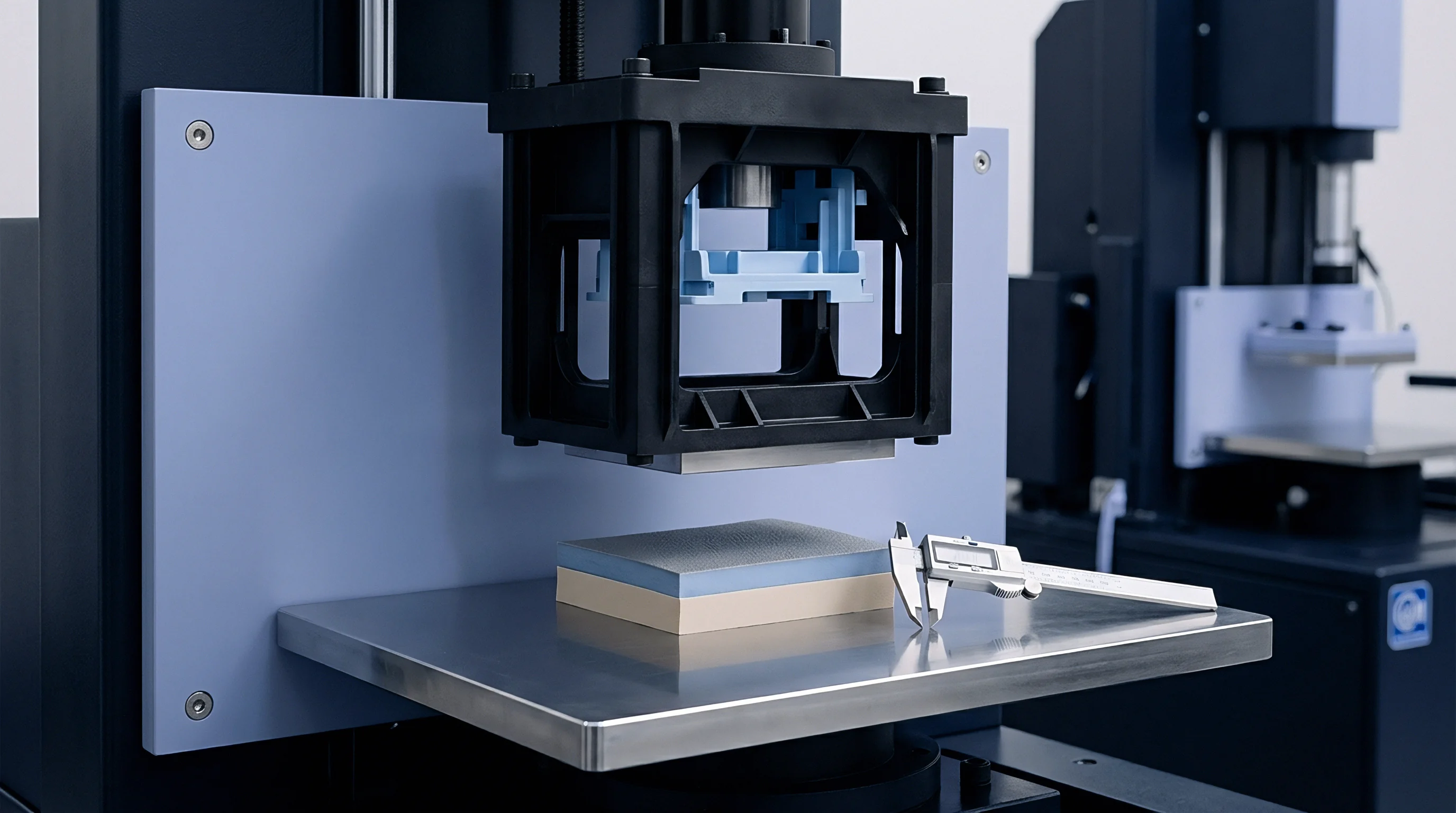
Flank
Draft walls tilted at narrow angles present geometric capture boundaries for optical coherence probes. When incident light strikes a vertical sidewall with zero draft, specular reflection bounces photons downward toward the cavity floor rather than back along the illumination path. As draft angles increase beyond one degree, specular reflection directs the beam away from the collection aperture entirely, leaving only microscopic surface micro-roughness to scatter photons back into the objective lens.

Can Low Coherence Systems Gauge Narrow Cavity Channels?
Channel geometry governs ray return trajectories. In deep rib pockets with aspect ratios of ten to one, light scattered from lower sidewall regions undergoes secondary reflections against opposing steel faces before exiting the aperture. These multi-path reflections manifest as ghost surfaces positioned beneath the actual physical boundary in reconstructed tomograms.
Ray tracing through cavity cross-sections reveals that secondary reflections produce false depth echoes when draft angles drop below one half degree. The receiver loses signal.
Steep draft walls deflect reflected rays away from collection lenses unless the numerical aperture captures the angled return cone.
Side walls cast shadows. Calibrating signal thresholds against secondary echoes prevents false wall identification during computerized surface extraction. Setting polarization filters isolates single-scatter events from cross-polarized multi-bounce trajectories, suppressing ghost boundaries in deep pockets cut into 1.2343 tool steel.
The optic moves downward.
| Draft Angle | Steel Surface Finish | Returned Power Fraction | Apparent Position Error | Profile Fidelity |
|---|---|---|---|---|
| 0.25 Degree | VDI 18 Wire EDM | 0.0004 | 14.2 µm | Unreliable Flank Reconstruction |
| 0.50 Degree | VDI 24 Sinker EDM | 0.0018 | 6.8 µm | Marginal Trace Boundary |
| 1.00 Degree | Ra 0.4 µm Polished | 0.0065 | 2.1 µm | Stable Coordinate Capture |
| 2.00 Degree | Ra 0.8 µm Ground | 0.0210 | 0.8 µm | Verified Geometric Boundary |
| 3.00 Degree | VDI 30 Textured | 0.0480 | 0.4 µm | Full Envelope Acquisition |
Tool setters verify cavity release characteristics by tracking draft conformance along deep rib heights. When an electrical discharge machining operation produces electrode wear toward the bottom of a blind pocket, the drafted wall narrows prematurely. Standard coordinate probes cannot reach inside features narrower than one millimeter without contacting opposing faces.
Low coherence optical heads scan these channels continuously, plotting taper profiles from split line to cavity base.
Executing an optical inspection run inside deep cavities follows an operational sequence:
- Mould Surface Degreasing removes residual rust inhibitors, cutting fluid films, and protective waxes that introduce spurious refractive layers over tool steel.
- Datum Sphere Alignment establishes the mechanical coordinate system between external mould parting planes and the non-contact optical sensor head.
- Aperture Centering Routine aligns the optical beam parallel to the tool draft vector, preventing physical vignetting against high cavity shoulders.
- Signal Threshold Normalization adjusts source laser power to balance dynamic range between bright bottom flats and dark drafted sidewalls.
- Volumetric Cloud Extraction filters secondary multi-path ghost reflections out of the digitized raw interference fringes.
Mould manufacturers frequently assert that high-aspect pockets below one millimeter width cannot reflect sufficient light for non-contact metrology, claiming mechanical contact scrapers remain the sole defensible validation method for steep tool flanks.


Scatter
Surface roughness generated by machining processes dictates optical scatter patterns inside cavities. High-speed milling tools leave regular cusps whose peak-to-valley heights match optical wavelengths, creating diffraction grating responses. When broadband light strikes periodic tool marks, reflected rays separate into distinct diffraction orders.
If the objective lens aperture fails to capture first-order diffraction modes, the reconstructed interferogram exhibits signal dropout along tool feed paths.

Will Surface Specularity Degrade Signal Autocorrelation Peaks?
Specularity concentrates reflected energy into narrow angles, overloading detector arrays when beam trajectories sit normal to cavity surfaces. Electrical discharge textured surfaces, conversely, scatter incident light across Lambertian distributions. Sinker EDM cavities finished to VDI 34 produce diffuse scatter where only a tiny fraction of photons returns along the incident collection axis, forcing instrumentation to operate with wide dynamic ranges exceeding one hundred decibels.
ISO 25178 surface data gathered without proper dispersion compensation triggers tool rejection during qualification audits.
Fringe contrast drops rapidly. Roughness elements greater than one fourth of the source wavelength randomize phase relationships across the focal spot, washing out interference fringes. Operating at 1310 nanometers tolerates rougher surface textures than visible light systems because longer wavelengths experience lower optical phase disruption over equivalent physical surface peaks.
Roughness scatters incident light.
Spatial filtering techniques reject high-angle diffuse scatter while collecting specular returns from micro-machined flats. Optical coherence tomography algorithms apply adaptive thresholding across depth scans to separate actual steel boundaries from airborne particulate scatter inside the cavity. When clean compressed dry air purges the cavity during data acquisition, airborne oil mists and dust particles vanish from raw point clouds.
Pockets trap cooling fluid.
Interferograms record phase differences. Toolmakers evaluating EDM cavities must monitor both surface profile and underlying recast white layers. Near-infrared wavelengths penetrate non-metallic dielectric oxide layers, reflecting from the pure substrate boundary beneath.
Interpreting this interface requires knowing the refractive index of the oxide film, otherwise optical delay through the film appears as extra physical cavity depth.
Failure to isolate oxide layer refraction from physical steel geometry leads toolmakers to machine corrective passes into core inserts, creating undersized mould geometries that produce out-of-spec plastic components during initial trial runs.


Audit
Tooling qualification dossiers require traceable depth validation before production sign-off. Optical coherence data sets provide three-dimensional surface topographies that populate quality management records without cutting destruct sample blocks from production inserts. Comparing measured point clouds directly to native computer-aided design models reveals thermal sink distortions, core shift, and spark erosion variances across multi-cavity plates before steel ships to moulding shops.

Cavity Certification and Landed Cost Economics
Metrology cycle time directly impacts tooling delivery schedules. Tactile coordinate measuring machines with micro-styli execute deep pocket inspection at rates of two to five points per second, consuming four to eight hours to map a single sixteen-cavity injection mould. Low coherence optical scanners acquire fifty thousand depth points per second, reducing cavity scan durations to under ten minutes while providing complete areal coverage under ISO 25178 guidelines.
Cycle time costs money. Fast non-contact validation shortens tool commissioning cycles by three to four business days per iteration. When an export injection tool involves thirty-two complex connector cavities, comprehensive pre-shipment metrology prevents cross-border shipping delays triggered by first-article part shrinkage disputes at the destination plant.
Calibration plates supply datum points.
| Cavity Count | Inspection Method | Total Audit Duration | Equipment Capital Outlay | Cost Per Validated Cavity |
|---|---|---|---|---|
| 8 Cavities | Contact Micro-Stylus CMM | 3.5 Hours | $160,000 | $85 |
| 8 Cavities | Low Coherence Tomography | 0.4 Hours | $195,000 | $28 |
| 32 Cavities | Contact Micro-Stylus CMM | 14.0 Hours | $160,000 | $78 |
| 32 Cavities | Low Coherence Tomography | 1.2 Hours | $195,000 | $14 |
| 64 Cavities | Contact Micro-Stylus CMM | 28.5 Hours | $160,000 | $72 |
| 64 Cavities | Low Coherence Tomography | 2.1 Hours | $195,000 | $9 |
Coordinate verification ties directly to commercial payment releases. Purchasing agreements incorporate geometric milestone clauses where the buyer withholds thirty percent of tooling capital until cavity point clouds match CAD models within DIN 16742 tolerance bands. Contractual clauses specifying optical coherence scan deliverables bind tool suppliers to non-destructive verification records, shifting the burden of micro-feature proof directly onto the toolmaker before release payment authorization.
Tool supply agreements governing export injection tooling enforce DIN EN ISO 1101 geometry verification through digital point cloud submission, requiring tool shops to deliver full-cavity surface scans alongside initial T1 plastic shot samples before final capital disbursement releases.