Modular Tooling Architecture and Hot Runner Valve Gate Control Economics
Modular tooling with valve gates cuts changeovers to 30 minutes and trims cycle times, amortising higher initial tooling capital across program variants.

Interface
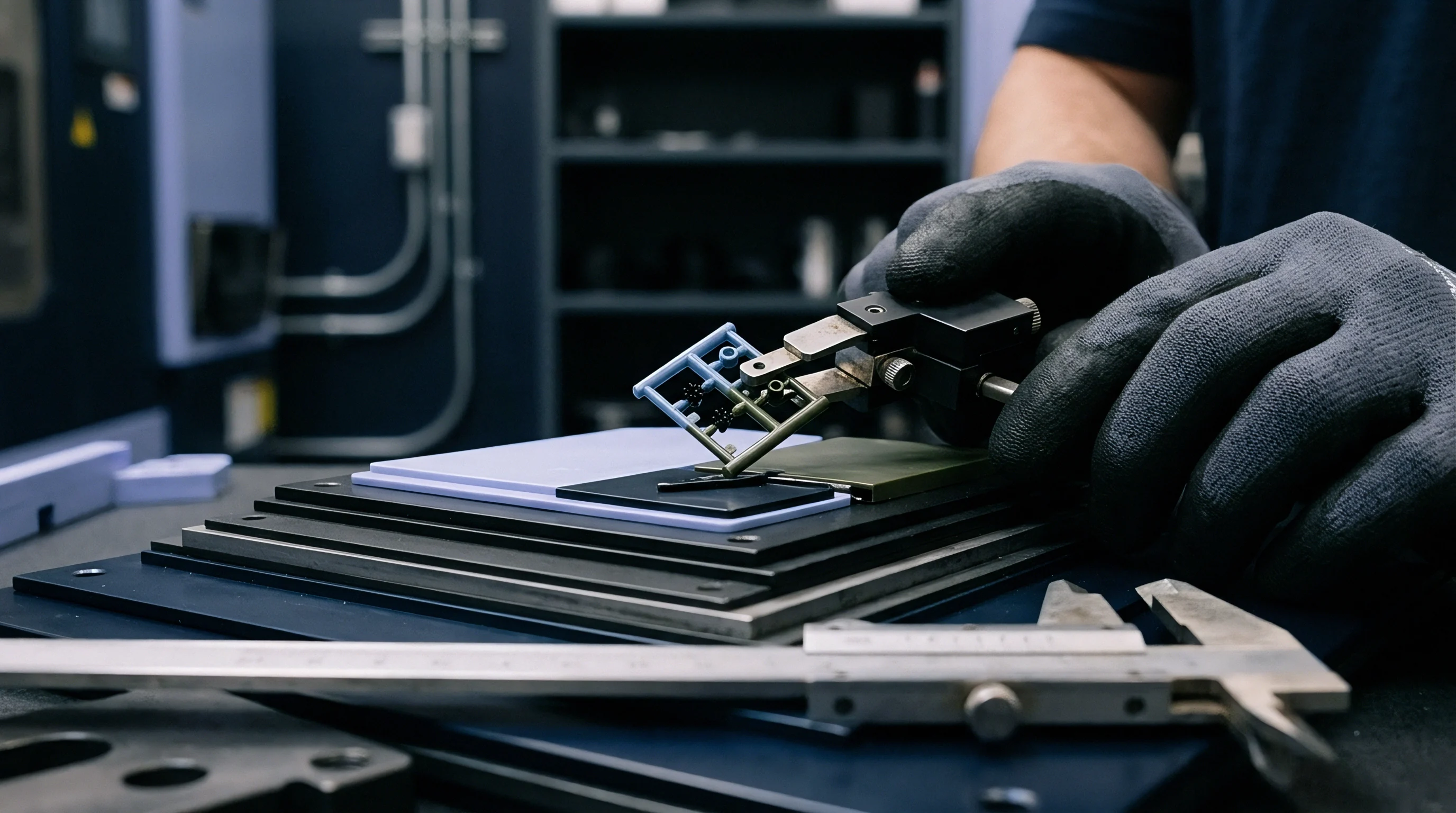
Modular tooling architecture establishes an operational boundary between standard mould frames and interchangeable cavity cassettes. In high-mix, medium-volume manufacturing, standardising the bolster plate, cooling connections, and ejection grid isolates product-specific geometry inside drop-in core and cavity inserts. A precision master frame machined from 1.2312 or 1.2738 pre-hardened tool steel remains mounted in the injection moulding press.
Toolmakers machine custom geometries exclusively within standardised insert blanks, reducing machining volume by up to sixty percent per iteration. Standardisation confines the custom investment to the parting line and impression details. Tooling investment shifts from dedicated monolithic steel blocks to compact cavity inserts that exchange within thirty minutes without dropping water lines from the platen.
A standard bolting grid requires thermal and mechanical isolation from the machine platen to maintain insert interchangeability across extended production campaigns. Bolster plates incorporate hardened guide plates and locating gibs ground to a tolerance of plus or minus five microns. These gibs absorb injection clamp loads while preventing lateral dislocation between cavity sets.
Thermal expansion differences between the insert core and the master pocket generate mechanical interference when insert temperatures swing during processing. Incorporating four-point wedge locks around each cassette perimeter directs expansion outward along predictable axes, preserving guide pin alignment and preventing parting line galling.

Modular Cassette Mechanics
Cassette alignment relies on direct mechanical interlocks rather than the guide pins of the master shoe. Toolrooms finish master pockets with ground corner radii and taper blocks hardened to 58 HRC. The mating insert blanks receive complementary precision-ground taper seats, establishing zero-clearance engagement when the clamp reaches eighty percent of operating tonnage.
This mechanical arrangement isolates the primary cavities from platen deflection. Standardised quick-change water manifolds use flush-face flat couplings mounted directly behind the insert pocket. Ejector plates inside the cassette couple directly to the machine ejector beam through central quick-release pull couplings, eliminating individual rod adjustments during tool setups.
Interchangeable inserts inevitably introduce micro-deflections under high injection pressure. Cavity cassette base thicknesses follow strict minimum depth-to-width ratios of 1:3 to resist bending moments under peak hydraulic pressure. Inserts supported by insufficient backing plate thickness bow across the center during the intensification stage.
That deflection flashes the inner parting lines while simultaneously binding adjacent ejector pins. Finite element calculation of cassette bending requires an upper threshold of 0.02 millimetres total deflection under maximum injection pressure. Deflections exceeding this value degrade part shutoffs and accelerate parting line fatigue across standard tool steels.

Thermal Boundaries across Insert Pockets
Conductive heat transfer between an interchangeable insert and its pocket fluctuates across tool changeovers. An air gap as thin as 0.03 millimetres along cassette sidewalls creates an insulating barrier, slowing heat migration into the master mould frame. Temperature control circuits remain fully contained inside the cassette body rather than bridging parting gaps via O-rings.
Cassette water channels rely on deep-hole drilling with baffled circuits placed within fifteen millimetres of the cavity surface. Dedicated cooling channels maintain the insert temperature window within three degrees Celsius across the entire moulding face.
Unequal thermal expansion between the cassette and the bolster pocket creates dimensional binding during preheating. Machining the pocket clearance to 0.025 millimetres per side at room temperature allows the insert to seat cleanly when preheated to eighty degrees Celsius in an external staging station. Preheating cassettes before press loading eliminates thermal waiting periods, cutting active press downtime to twenty minutes per exchange.
A tool setter rolls the warm insert directly into the bolster pocket, engages the pneumatic locking wedge, latches the ejector coupler, and connects the quick-lock cooling bank. Production resumes without cycling press clamp hydraulics over extended thermal recovery intervals.
Cassette base thickness demands a minimum 1:3 depth-to-width ratio to keep center deflection below twenty microns under peak cavity pressure.
A supplier often states that universal pocket clearances absorb all insert thermal growth without sacrificing cavity pitch tolerance.


Pin
Hot runner valve gate systems use mechanically driven stem pins to seal the gate orifice mechanically at the parting line, replacing thermal freeze-off gates. Direct valve gating leaves a cylindrical vestige flush to within 0.05 millimetres on the plastic component, avoiding the protruding gate stub typical of hot tip systems. Pin actuation occurs via pneumatic cylinders, hydraulic pistons, or direct servo-electric linear actuators mounted on the top clamp plate.
The pin advances forward through the melt channel, penetrating the nozzle tip orifice to sever the polymer flow at cavity pack completion. This positive mechanical shutoff permits large gate diameters between 1.5 and 3.5 millimetres without drool, stringing, or premature gate freeze.
Mechanical closure decouples gate seal time from runner thermal freeze dynamics. The moulder packs the cavity until the volumetric shrinkage target is reached, then drives the pin into the valve seat before holding pressure decays. Gate freeze happens instantly via mechanical displacement rather than progressive conductive cooling of the plastic skin.
This mechanical action allows the cycle to transition directly into the cooling and plasticizing phase, shaving multiple seconds off heavy-wall cycle profiles. The pin maintains its closed position throughout screw recovery and mold opening, preventing melt seepage into the open parting line.
| Actuation Medium | Response Time (ms) | Positional Accuracy (mm) | Force Generation (N) | Cleanroom Suitability |
|---|---|---|---|---|
| Pneumatic (Compressed Air, 6-8 bar) | 80 – 150 | Fixed stroke stops | 600 – 1800 | Exhaust filtration required |
| Hydraulic (Press Circuit, 40-70 bar) | 30 – 60 | Fixed stroke stops | 2500 – 6500 | Leak risk limits cleanroom use |
| Servo-Electric (Direct Ball Screw Drive) | 5 – 15 | ±0.002 | 1200 – 4500 | ISO Class 5 compliant |
| Magnetic Linear Actuator | 2 – 8 | ±0.005 | 800 – 2200 | ISO Class 4 compliant |

Stem Kinematics and Seat Geometry
The interface between the pin tip and the nozzle gate insert dictates gate vestige quality and maintenance life. Cylindrical land shutoffs slide the pin tip into a parallel bore with 0.004 millimetre diametral clearance. Tapered shutoffs land the pin against an angled conical seat, typically between twenty and thirty degrees.
Cylindrical land designs absorb pin thermal expansion without altering gate seal diameter, though polymer shear increases as the pin shears through the entering melt stream. Tapered seats eliminate this shearing action, but axial thermal expansion of the manifold pushes the pin deeper into the conical seat, risking seat deformation or pin jamming.
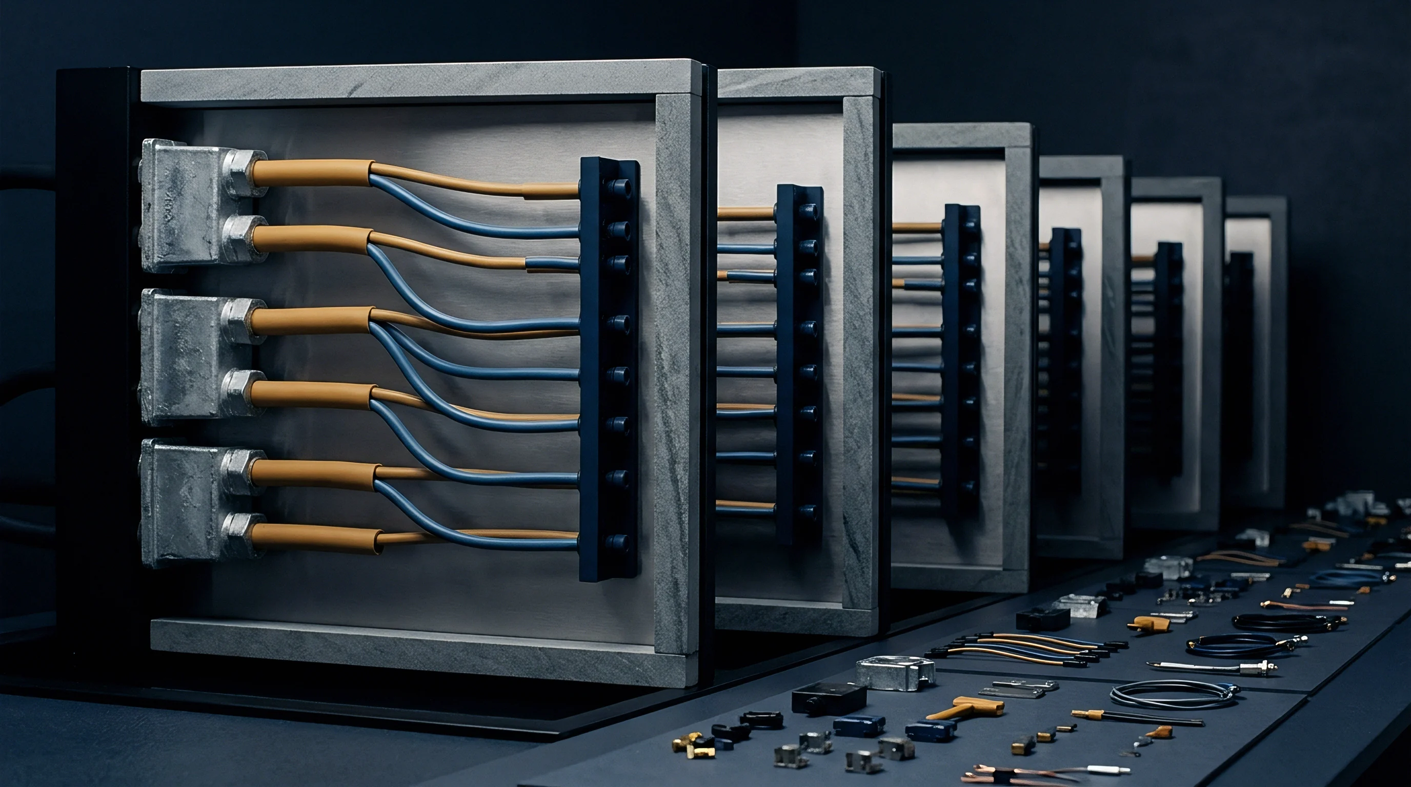
Pin guidance depends on tight cylindrical alignment through the backing plate, melt manifold, and nozzle housing. Manifold thermal expansion moves nozzle centerlines relative to the cold actuator cylinders mounted on the top clamp plate. Floating pin connections permit radial movement of the stem head inside the actuator coupling, compensating for the 0.8 to 2.2 millimetres of manifold thermal growth encountered at processing temperatures between 200 and 300 degrees Celsius.
Pin shafts pass through double-bushed melt seals machined from heat-treated beryllium-copper or sintered tool steels. These seals maintain clearances under 0.008 millimetres, holding high packing pressures without allowing degraded polymer to seep into the actuator housing.
Polymer Degradation at the Stem Seal
Melt leakage around the valve stem represents an insidious failure mode in hot runner operations. High injection pressure drives molten polymer up the annular clearance between the sliding pin and the nozzle melt bore. Residence time inside this sliding seal exceeds hundreds of production shots, subjecting the trapped resin to prolonged thermal degradation.
Thermal breakdown of resins like polycarbonate or polyamide forms hard carbonaceous char along the sliding surfaces. This abrasive debris scores both the ground stem shaft and the guide bushing, enlarging clearances and accelerating further polymer blow-by.
Preventing carbon crust formation requires controlled cooling around the upper pin guide bushings. Mould designers run dedicated water lines through the top clamping plate immediately adjacent to the pin packing seals. Maintaining pin seal temperatures below the resin glass transition or crystallization point prevents melt creeping along the stem from remaining molten.
The resin skins against the steel surface, forming a self-sealing plug that resists displacement. Worn seals permit melt ingress into pneumatic actuator pistons, causing stroke drag, irregular closing times, and asymmetric gate marks across multi-cavity layouts.
Standard quality agreements state that gate vestige height exceeding 0.10 millimetres constitutes structural defect rejection on class-A visual surfaces.
Timing
Controlling the exact millisecond each valve gate pin opens alters cavity filling dynamics. In cascade or sequential injection moulding, valve pins do not retract simultaneously when the injection screw advances. The gate closest to the part edge opens first, filling the volume until the melt front sweeps past the downstream gate location.
The downstream valve gate pin then retracts smoothly into the melt stream. Introducing material behind an advancing melt front eliminates the pressure spikes and high shear zones that occur when an unvented melt front impacts a stationary boundary wall.
Cascading prevents weld lines in long, thin-walled plastic components. When melt streams from two distinct gates converge head-on, the frozen skins meet at temperatures below the bulk melt, creating an interface of reduced tensile strength and optical flaws. Opening downstream gates only after the forward melt front passes prevents opposing fountain flows from colliding.
The polymer maintains continuous forward momentum through the cavity. This sequencing technique suppresses witness knit lines, eliminates cold gas traps, and reduces overall clamp tonnage requirements by distributing hydraulic injection force along the part length.
Pressure Drop Management and Knit Line Suppression
Conventional multi-point hot runner gating forces material simultaneously through balanced nozzles, generating high clamp tonnage demands. The machine must generate enough hydraulic pressure to fill the longest flow path while counteracting the viscous resistance of cooling resin inside the cavity. Sequential gating lowers this requirement by maintaining flow across shorter instantaneous flow paths.
Injection pressures drop by fifteen to thirty percent because the effective fill area active at any single moment remains bounded. The press runs at lower peak line pressures, extending hydraulic seal life and lowering energy consumption across sustained production schedules.
Premature downstream pin actuation reintroduces the very defects cascading seeks to prevent. If a downstream valve pin opens when the advancing melt front is three millimetres short of the gate orifice, cold gas and low-pressure resin squirt into the cavity before the main front arrives. This produces severe hesitation marks, silver streaking, and low-density voids under the gate skin.
The secondary pin opening signal ties directly to screw stroke position or cavity pressure transducer triggers mounted flush along the runner path. Triggering from pressure sensor feedback guarantees that the melt front pressurizes the local gate zone to at least fifty bar before the pin retracts.

Are Transducer Triggers Superior to Position Signals?
Position-based timing links valve actuation to the linear position of the press injection screw. A linear optical encoder tracks screw advancement, triggering solenoid valves when the screw crosses calibrated displacement marks. While simple and reliable, position-based sequencing presumes identical melt compressibility and shot weight consistency across consecutive cycles.
Bulk density shifts between raw material batches, regrind ratio swings, and check-ring slippage cause the physical melt front to lead or lag the screw position. A check-ring leakage of 1.5 millimetres displaces the actual melt front by up to twenty millimetres inside thin-walled cavity profiles.
In-cavity piezoelectric pressure transducers provide direct verification of the melt front location. Mounted flush in the cavity steel two millimetres upstream of each gate, these sensors detect the instantaneous thermal and pressure spike caused by the approaching plastic skin. The sensor sends a millivolt signal through a digital charge amplifier to the hot runner controller, triggering pneumatic or servo actuation within five milliseconds.
Transducer-driven sequencing adapts to batch viscosity variations in real time, stabilizing weld line locations and part densities even when resin melt flow index drifts by ten to fifteen percent between raw material deliveries.
Sequential gate pins triggered by screw position drift when check-ring leakage or resin bulk density changes the true melt front velocity.
When sequential timing fails to balance flow fronts, parts exit the cavity with localized residual stresses that warp flat surfaces once the mould opens.
Friction
Linear pin actuation inside hot runner manifolds creates severe mechanical friction under continuous high-temperature service. Valve pins machined from H13 or M2 high-speed tool steel operate at continuous temperatures ranging from 200 to 320 degrees Celsius. Uncoated pins cycling inside bronze or steel bushings experience adhesive wear and micro-welding along the guiding surfaces.
As frictional drag escalates, pneumatic actuators operating at six bar line pressure exhibit erratic cycle times. The pin stutters during opening and closing, disrupting the precise millisecond cascades required for cosmetic surface finishes.
Thermal expansion mismatches exacerbate frictional resistance inside the nozzle stack. The hot manifold block expands outward from its central locating dowel, while the top clamping plate hosting the actuators runs significantly cooler due to mold cooling circuits. Misalignment forces the pin to deflect laterally as it spans the distance from the actuator piston to the nozzle tip.
This bending moment loads the guide bushing unevenly, concentrating contact pressures onto small bearing lands. Tool life drops precipitously without specialized wear mitigation strategies integrated directly into the pin assembly.
Surface Metallurgy and Wear Coatings
Advanced physical vapor deposition (PVD) coatings deposit hard, low-friction films onto sliding valve pin shafts. Chromium nitride (CrN) and diamond-like carbon (DLC) coatings provide surface hardness values exceeding 2000 HV while lowering dry friction coefficients below 0.15 against steel. CrN handles operating temperatures up to 600 degrees Celsius without oxidation, making it the standard choice for technical resins like polybutylene terephthalate and polyphenylene sulfide.
DLC coatings offer superior lubricity at lower processing temperatures, preventing polymer adhesion and resin carbonization on the pin stem.
Titanium aluminium nitride (TiAlN) coatings protect stems running abrasive, glass-filled compounds. Formulations containing thirty to fifty percent chopped glass fibers act like high-speed grinding pastes within the gate orifice. The pin tip must sever these fibers cleanly on every cycle without chipping or abrasive gouging.
A TiAlN film forms an aluminium oxide passive layer at elevated contact temperatures, shielding the underlying M2 substrate. Treating valve pins with vacuum gas nitriding before coating application yields a hard case depth of 0.05 millimetres at 65 HRC, preventing substrate collapse under heavy localized impact loads against the nozzle seat.

Actuator Stroke Drag and Valve Response Drift
Piston seal degradation inside pneumatic and hydraulic actuators introduces uncontrolled timing variance across cavities. Fluoroelastomer (FKM) and perfluoroelastomer (FFKM) seals operating near heated manifolds experience gradual polymer embrittlement. As elastomeric O-rings lose flexibility, frictional drag rises from fifty newtons to over three hundred newtons per actuator cylinder.
This drag delays pin opening by thirty to seventy milliseconds. In cascade systems, such delays disrupt the coordinated sequencing window, forcing melt past closed gates and creating severe localized shear burning.
Servo-electric linear actuators replace fluid cylinders to eliminate seal-related friction drift. Direct-drive servo motors use precision ground ball screws or roller screws to translate rotational torque into linear stem movement. Integrated optical encoders track absolute pin position within two microns, providing dynamic force feedback throughout the stroke profile.
The controller senses mechanical resistance during the seating stroke, modulating motor current to land the pin gently into the gate insert without impact shock. Servo actuators eliminate compressed air consumption, hydraulic oil contamination risks, and mechanical stroke timing drift over millions of continuous moulding cycles.
A supplier often argues that standard pneumatic cylinders with Viton seals operate reliably for multiple years without cooling plates or maintenance rebuilds.


Cost
Capital outlays for modular tooling architectures and valve-gated hot runner systems require justification through unit production economics. A custom four-drop hot runner system with pneumatic valve gate actuation adds 18,000 to 32,000 USD to a standard injection mould budget compared to a cold runner configuration. Upgrading to servo-electric valve actuation raises this premium to between 40,000 and 65,000 USD, driven by multi-axis motion controllers, precision servo drives, and integrated software licenses.
Modular bolster frames introduce an initial capital tooling charge of 12,000 to 25,000 USD for the master pocket shoe, guide gibs, and automated ejector coupling systems.
Financial recovery on these tooling investments hinges on resin conservation, cycle time contraction, and tooling reuse across product variants. Cold runner systems generate ten to forty percent scrap runner weight per shot, which must be granulated, blended, or discarded. Hot runners eliminate the runner entirely, dropping raw material consumption directly to part net weight.
In high-volume production of engineering polymers like PBT, POM, or PA66 costing between 3.50 and 8.00 USD per kilogram, raw material savings alone often amortise hot runner capital costs within the first three hundred thousand shots.
| Tooling Architecture | Initial Tool Cost (USD) | Cycle Time (s) | Scrap Rate (%) | Amortised Cost Per Part (USD) |
|---|---|---|---|---|
| Monolithic Cold Runner Tool (4 Cavities) | 38,000 | 28.5 | 14.5 | 0.380 |
| Modular Cold Runner Cassette (4 Cavities) | 24,000 | 29.0 | 15.0 | 0.240 |
| Modular Hot Runner Open Tip (4 Cavities) | 46,000 | 22.0 | 2.0 | 0.460 |
| Modular Valve Gate System (4 Cavities) | 62,000 | 17.5 | 0.5 | 0.620 |

Scrap Elimination versus Capital Outlay
Quantifying resin scrap recovery requires rigorous material balance calculations across projected program volumes. The calculation isolates the material cost differential per part:
Material Savings = (Runner Weight in Kilograms Resin Price per Kilogram) + (Regrind Degradation Yield Loss)
Processing thirty percent regrind into structural parts introduces ten to fifteen percent tensile strength variance. Medical, optical, and safety components prohibit regrind entirely under regulatory frameworks like ISO 13485 or automotive IATF 16949 standards. When regrind is barred, every gram of cold runner constitutes net financial waste sold at severe scrap discounts.
A four-cavity tool producing a twenty-gram component with a fifteen-gram cold runner discards 1,500 kilograms of virgin resin per one hundred thousand parts, representing over 7,500 USD in discarded material for a 5.00 USD/kg polymer.
Cycle time reductions contribute substantial machine-hour savings that surpass material recovery on high-speed moulding presses. Presses between 150 and 300 tonnes carry fully absorbed shop rates of 65 to 110 USD per machine hour. Eliminating cold runner cooling time and accelerating pin gate seal contracts cycle time from 28.5 seconds down to 17.5 seconds on a four-cavity technical component.
Over a one-million-part production order, this eleven-second cycle contraction recovers approximately 764 machine hours. That capacity recovery saves roughly 61,000 USD in press machine-hour charges, fully covering the initial valve gate capital investment.

Modularity Amortisation across Derivative Parts
Modular tooling architecture alters financial breakeven points for multi-variant product families. Once the capital investment in the master bolster frame is absorbed by the baseline program, subsequent product derivatives require only custom cavity inserts. Insert manufacturing costs drop thirty-five to fifty-five percent relative to full-frame monolithic moulds, running 14,000 to 22,000 USD instead of 45,000 USD per derivative.
This compressed upfront outlay lowers production break-even thresholds from 80,000 parts down to 25,000 parts, making short-run regional variations and product refreshes commercially viable.
Tooling transfer risk diminishes when using modular cassette platforms. The master bolster remains the asset of the contract manufacturer or the mould buyer, specified with universal tie-bar clearance dimensions. Transferring a program requires moving only the compact insert cassettes, weighing between thirty and eighty kilograms, rather than freighting a two-tonne monolithic mould assembly.
Cassettes ship by standard air freight within seventy-two hours, bypassing sea transit delays and customs impounds of heavy industrial steel. The receiving facility drops the inserts into an identical master bolster frame, validating parting line shutoffs and gate timing within a single shift.
Cycle time contraction from mechanical valve shutoff recovers sufficient press machine-hour charges to amortise system capital within one high-volume production year.
Omitting the thermal barrier between hot runner nozzles and modular insert cassettes results in uncontrolled heat soak, warping cavity details and causing part ejection jams.

Qualification
Tool qualification protocols for modular, valve-gated moulds require systematic decoupling of machine variables from tooling dynamics. Standard validation sequences follow a rigid three-stage protocol: installation qualification (IQ), operational qualification (OQ), and performance qualification (PQ) conducted per ISO 13485 and DIN 16742 frameworks. The tool qualification dossier documents steel hardness certifications, hot runner manifold balance data, thermal mapping profiles, and statistical capability indices across all cavities.
Qualification establishes that the modular cassette locks securely into the bolster without parting line mismatch exceeding 0.008 millimetres under maximum clamp force.
Determining the robust operating window demands comprehensive design of experiments (DOE) runs at the press. Technicians vary barrel temperatures, injection velocities, pack pressures, and pin timing sequences across twenty-seven structured trial runs. Cavity pressure transducers track filling symmetry across the cassettes, ensuring that cavity-to-cavity pressure variation remains below three percent at peak pack.
Parts sampled across the experimental window undergo full optical metrology, verifying critical-to-quality dimensions across shrink-attached features against DIN 16742 tolerance group TG4.

Statistical Process Verification at Volume
Long-term process capability requires tracking key dimensions across unbroken production runs spanning multiple shifts. Statistical process control monitors dimensional drift, pin wear, and thermal shifts over fifty thousand consecutive parts. Verification protocols define strict capability limits:
- Process capability index (Cpk) exceeding 1.33 across all critical functional dimensions under continuous operation.
- Cavity pressure variation maintained within a plus or minus 2.5 percent tolerance band across all monitored drops.
- Gate vestige uniformity held below a 0.05 millimetre protrusion threshold across the entire production lot.
- Cassette pocket temperature stability maintained within a two-degree window across twelve hours of uninterrupted cycling.
A dimensional study requires measuring thirty consecutive parts from each cavity taken at four distinct intervals: startup, mid-run, post-material-lot change, and shutdown. Dimensions measured across the modular parting line undergo capability evaluation using standard normal distribution models. If parting line flash creeps above 0.03 millimetres or core-side dimensions drift toward upper tolerance limits, technicians halt the press to inspect cassette seating gibs for contamination or clamp force decay.
The toolmaker checks the torque on insert retention bolts, confirming clamping preload matches calibration specifications.
Documenting Tool Asset Transfers and Warranties
Tool purchase agreements must explicitly delineate asset boundaries between master bolster frames and modular cavity cassettes. Contracts define whether the mould buyer owns the master shoe or simply leases press time on a toolmaker-owned standard bolster. The tooling specification dossier mandates inclusion of detailed manufacturing prints for every wear component, including valve pins, nozzle tips, guide bushings, and pocket gibs.
Valve pin replacement intervals are warranted to a minimum of one million cycles under standard processing conditions for non-abrasive polymers, with clear wear allowances defined for glass-filled grades.
A comprehensive tooling warranty includes explicit remedies for hot runner manifold leakage, heater element burnout, and gate orifice erosion. Toolmakers guarantee nozzle thermal uniformity within five degrees Celsius across the entire drop array under production throughputs. Failure to maintain balanced gate shutoffs during the initial five hundred thousand cycles obligates the tooling supplier to provide replacement gate inserts and recalibrated valve pins at no additional cost.
The tooling sign-off dossier remains incomplete until the moulder executes a continuous twenty-four-hour unattended qualification run, generating parts that pass all dimensional, optical, and mechanical durability specifications without a single manual intervention.
Contracts govern the mechanical handoff by establishing that tool ownership transfers only upon final delivery of a passing statistical capability study.

Maintenance
Preventive maintenance cycles dictate the operational reliability and service life of modular valve-gated tooling systems. Unlike conventional open-nozzle cold runner moulds, valve gate systems contain tight-tolerance dynamic mechanisms operating inside harsh thermal environments. Routine servicing protocols divide into three operational tiers: press-side cleaning every shift, cassette servicing every one hundred thousand cycles, and full manifold overhauls every five hundred thousand cycles.
Skipping intermediate service intervals invites catastrophic polymer leakage behind the manifold, requiring complete tool teardown and cryogenic blasting to recover salvageable steel.
Press-side maintenance centers on visual inspection of the gate vestige, cavity shutoffs, and valve pin alignment. Technicians inspect the parting line for micro-flashing that indicates cassette pocket particulate contamination or clamping wedge wear. Lubricating the ejector pin plates and guide pillars requires high-temperature synthetic greases rated to 250 degrees Celsius to prevent grease migration onto visual cosmetic part surfaces.
Actuator air supply filters require daily drainage, as particulate and oil mist inside factory pneumatic lines corrode internal cylinder walls and degrade valve pin cycling response times.
Stepwise Disassembly of Cassette and Stem Units
Servicing modular inserts requires structured bench procedures to avoid damaging calibrated valve surfaces. Toolmakers execute disassembly following an established sequential workflow:
- Pre-disassembly inspection documents the baseline condition of parting lines, ejector pins, and gate orifices under 20x magnification.
- Pneumatic system isolation depressurizes actuator lines and verifies that all valve pins rest in the fully retracted position.
- Insert extraction uses balanced mechanical puller studs to slide the cassette out of the bolster pocket without cocking the guide gibs.
- Pin stem removal decouples actuator linkages and withdraws the valve stems rearward through the guide bushings to prevent tip scoring.
- Ultrasonic cleaning dissolves polymer deposits from pins, nozzles, and gate inserts using specialized chemical cleaning baths.
- Micrometer inspection checks valve pin straightness to within 0.005 millimetres total indicator reading along the entire shaft length.
During reassembly, toolmakers torque insert clamping bolts in an alternating cross-pattern to specified mechanical values. Installing pins through the melt bushings requires dedicated alignment sleeves to prevent the hard pin tip from clipping the edge of the internal bronze guide land. Once assembled, the toolmaker connects pneumatic lines to test actuation smoothness, measuring opening and closing velocities across all drops with digital dial indicators.
Pins exhibiting sticky movement or stroke discrepancies exceeding ten milliseconds require immediate bushing replacement before the cassette returns to the active production floor.

Refurbishment Costs and Component Wear Limits
Operating valve-gated tooling requires budgeting for recurring wear parts over multi-year production programs. Hot runner nozzle tips, gate inserts, and valve pins require planned replacement every 500,000 to 1,000,000 shots depending on polymer abrasiveness. Processing thirty percent glass-filled nylon erodes standard tool steel gate orifices within 250,000 cycles, enlarging gate diameters and producing heavy cosmetic flash.
Upgrading gate inserts to tungsten carbide or powdered metallurgy CPM 9V tool steels extends wear life past 1,500,000 shots, though component costs increase fourfold.
Budgeting dynamic tooling maintenance requires reserving approximately eight to twelve percent of the initial mould capital expense annually for refurbishment. A standard overhaul of a four-drop valve-gated modular system costs between 4,500 and 8,500 USD, covering new pin sets, replacement seal packs, thermocouple replacements, and surface re-polishing of cavity impressions. Neglecting scheduled pin seal replacements allows molten resin to migrate into the manifold wiring conduit, destroying ceramic band heaters and causing widespread electrical shorts across the hot runner control zones.
A plant manager will find that a worn valve pin that sticks during closing eventually collides with the closing core half, crushing cavity steel and halting the press.

Yield
Final production yield synthesises the mechanical integrity of the modular tooling cassette with the precision of the valve gate control loop. In high-speed commercial production, maintaining an overall yield above ninety-nine percent requires steady-state control over thermal, mechanical, and material variables. A failure in any single subsystem ripples across the process chain.
An uncalibrated manifold heater zone introduces local melt viscosity variations, which destabilise cavity filling velocities, force pin actuation out of sequence, and yield short shots or dimensional warpage that fails end-line automated optical inspection.
Modular tooling architecture isolates product obsolescence risk by protecting the major capital equipment investment over successive program lifecycles. When a part variant terminates its commercial run, the baseline capital investment in the master mould base, valve gate manifold, hydraulic cylinders, and machine automation interfaces remains fully intact. Sourcing teams procure only custom replacement cassette inserts for the next product launch, compressing lead times from eighteen weeks down to six weeks.
Production begins on proven, qualified infrastructure, avoiding the multi-week bring-up delays that accompany brand-new monolithic moulds.
The economic equation governing modular valve-gated tooling balances higher upfront system complexity against radical reductions in piece price, scrap volume, and changeover downtime. Sourcing directors who evaluate tooling quotes strictly on initial steel cutting costs overlook the compounding press-side efficiencies of hot runner automation. Over multi-million-part manufacturing lifecycles, precision control over the gate vestige, automated cycle contraction, and rapid modular tool exchange deliver structural cost advantages that outstrip initial tooling premiums within months of stable production.
The unresolved engineering frontier remains the real-time closed-loop modulation of individual valve pin velocities to counteract incoming viscosity shifts within a single injection stroke.