Thermal Drift Mechanics in Multi Cavity Hot Runner Manifolds
Engineered cold pitch offsets prevent valve tip shear, flash, and nozzle leakage in multi cavity manifolds operating at elevated molding temperatures.


Anchor
Hot runner manifolds require a fixed spatial datum to govern thermal growth. As the steel heats from ambient shop temperatures to processing setpoints between 200°C and 300°C, the block expands outward in all unconstrained directions. Without a mechanical anchor, expansion shifts unpredictably across the cavity layout, pushing nozzle tips out of alignment with mold cavity gates.

Kinematic Center and Thermal Origin Point
Locating pins locked into the back plate fix the geometry. Placing a single heavy dowel at the geometric center creates a stationary reference point from which all thermal expansion vectors radiate outward. Secondary guide slots or flat dowels aligned with the primary axes allow the block to expand linearly along its X and Y lengths while preventing rotation around the central axis.
Absolute displacement at any point on the manifold correlates directly with its linear distance from this thermal origin. Drops located near the central anchor shift very little relative to their cavity gates, whereas outer drops on high-cavitation manifolds experience maximum movement as expansion accumulates across the full length of the runner arm.
Thermal expansion originates from the mechanical anchor and accumulates linearly outward to the furthest manifold drop.
Restricting thermal growth with rigid mechanical stops introduces severe compressive stress into the tool steel. Because yield strength drops at elevated processing temperatures, unmanaged expansion can permanently distort the manifold or crush locating dowels. Pocket clearances must accommodate axial growth to maintain alignment integrity across thousands of thermal cycles.

Linear Expansion Mechanics in Tool Steel
Volumetric growth occurs proportionally along every unconstrained axis as thermal energy enters the H13 block. Calculating this dimensional increase relies on the linear expansion coefficient of the selected alloy, which remains fairly consistent across standard injection molding temperature ranges.
Calculating exact displacement requires multiplying the cold distance from the anchor by the temperature differential and the steel’s expansion coefficient. A 500 mm manifold section heated across a 200°C delta expands roughly 1.28 mm along its long axis ~ a variance toolmakers machining cavity plates at room temperature must account for precisely.
Unequal mechanical restraint across opposing manifold wings creates thermal bending moments. If clamping plates hold one side tighter than the other, thermal drift strays from the calculated axial path, skewing nozzle drops off centerline. Whether non-symmetric clamping forces on large manifolds can be passively balanced using spring-loaded support buttons without altering gate tip seal pressure remains a point of active toolroom debate.

Gradient
Heat distribution across a long distribution block is rarely uniform. Multi-zone heating circuits attempt to maintain isothermal conditions across complex runner layouts, but ongoing thermal losses into cooling channels, support pillars, and nozzle drops continuously pull energy away from the melt stream, creating persistent temperature variations across the steel structure.
Thermal Profile Mapping across Manifold Length
Thermocouple placement governs how control units power individual heating elements. Positioning a sensor too close to a heater triggers premature shutoff, leaving distant manifold sections under-heated. Conversely, placing a sensor too near a frame contact point drives continuous element firing, overheating adjacent melt channels and localized steel pockets.
Asymmetrical thermal profiles force uneven linear growth across opposing runner arms. If the left side of a symmetrical manifold operates 15°C hotter than the right side due to unequal cooling plate absorption, the left outer drops drift further from the anchor point than those on the right as pitches widen during soak.
Non-uniform temperatures induce thermal bowing along the longitudinal axis of long distribution manifolds. When the top surface runs hotter than the melt channel face, the block arches, lifting center drops away from the cavity plate while driving outer drops downward with heavy compressive force against gate pockets.

Why Do Hot Runner Drops Shift Unequally during Warm Up?
Outer extremities shed heat rapidly to the surrounding tool housing through radiation and contact air gaps. Internal manifold sections surrounded by hot melt channels retain heat longer and reach operating temperature faster. During the warm-up phase, center drops expand toward their nominal positions long before outer drops approach thermal equilibrium.
Standard temperature controllers register setpoint equilibrium at the thermocouple long before the physical mass of the tool steel achieves uniform heat distribution. Soaking the manifold at setpoint for thirty to forty-five minutes before bringing nozzle tips to temperature prevents running initial shots against unexpanded steel.
| Steel Grade | Mean Expansion Coefficient (20-300°C) | Expansion at 100mm Pitch (ΔT = 200°C) | Expansion at 400mm Pitch (ΔT = 200°C) |
|---|---|---|---|
| AISI H13 / 1.2344 | 12.8 µm/m·K | 0.256 mm | 1.024 mm |
| AISI P20 / 1.2311 | 12.0 µm/m·K | 0.240 mm | 0.960 mm |
| AISI 420 / 1.2083 | 10.5 µm/m·K | 0.210 mm | 0.840 mm |
| High-Conductivity Copper Alloy | 17.5 µm/m·K | 0.350 mm | 1.400 mm |
Unequal thermal gradients induce shear stress across the manifold structure, which manifests in specific physical tool failures during ongoing production cycles.
- Gate tip scuffing occurs when localized drop movement shifts the nozzle tip laterally against the cold cavity seal ring during thermal transient phases.
- Melt channel leakage develops at manifold extension joints where uneven expansion breaks sealing pressure between mating steel components.
- Valve pin binding results when thermal bowing tilts the valve guide bushing out of concentricity with the cavity gate land.
- Threaded nozzle galling appears on hot runner drops where non-uniform thermal growth concentrates clamping torque onto localized thread crests.
A hot runner system reaches true thermal stability only when the entire manifold mass holds uniform temperature, regardless of thermocouple setpoint indications.
Operating a multi-zone hot runner with adjacent zone setpoints differing by more than twenty degrees Celsius guarantees lateral drop misalignment that exceeds standard cavity gate sealing clearances.

Pitch
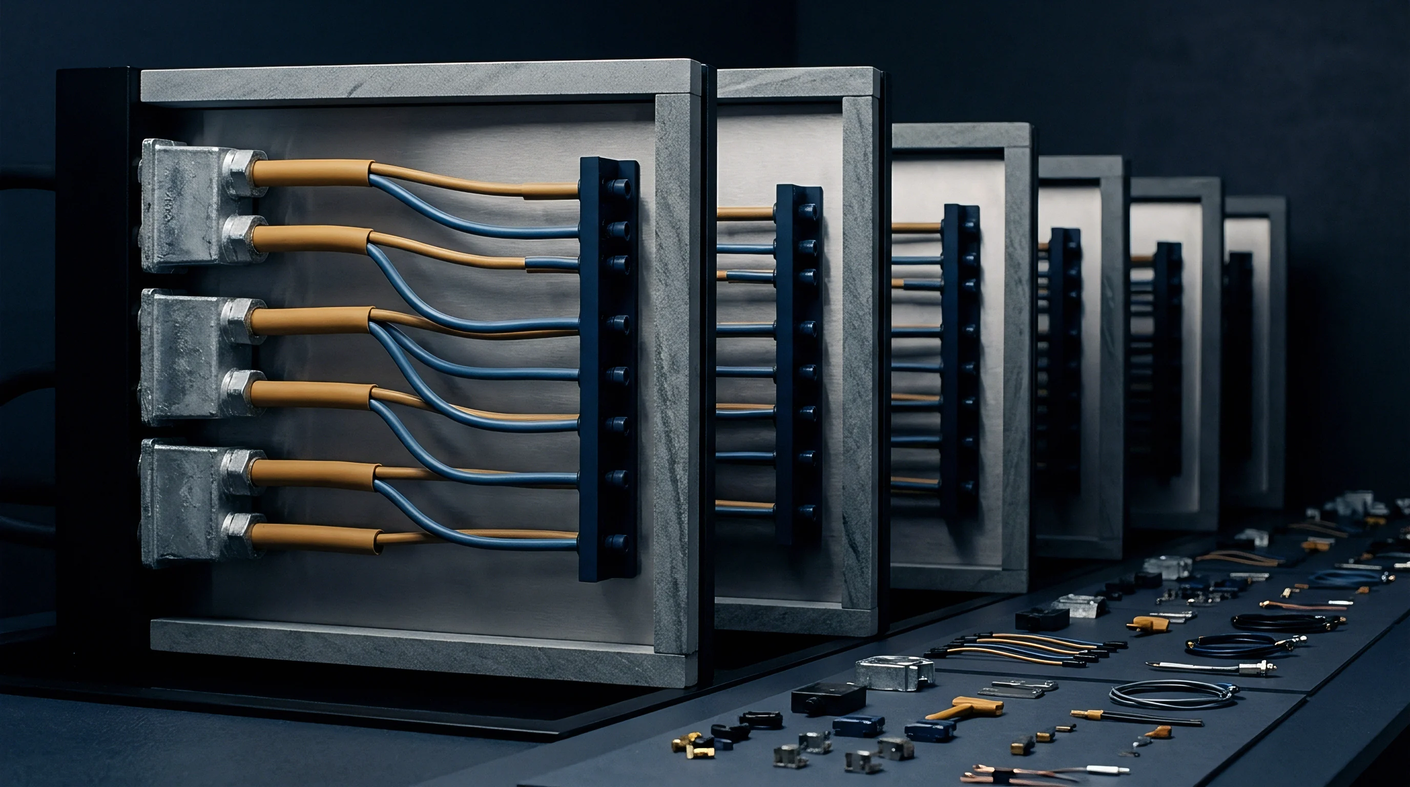
Distance between drop centerlines changes directly with operating temperature. Mold plates housing the cavities remain cool, kept at stable water temperatures between 15°C and 80°C to freeze the injected polymer, while the adjacent manifold operates hundreds of degrees hotter. This massive thermal delta creates continuous differential movement between fixed cavity gates in the mold plate and moving nozzle drops on the manifold.

Cold Machining Pitch versus Operating Centerline
Toolmakers cut cavity pockets into mold plates at standard ambient room measurements. Nozzle drop positions on the hot runner manifold cannot be machined at these same centerlines. If machined identical to the cold mold plate pitch, thermal expansion pushes every drop outward past its corresponding gate during operation.
Offsets must be applied in reverse during the CAD design stage, calculating cold manifold drop pitches shorter than target cavity gate pitches. As the manifold heats to processing temperature, thermal growth drives drop centerlines outward, aligning each nozzle tip precisely over its respective cavity gate.
| Cold Pitch (mm) | Target Delta T (°C) | Calculated Growth (mm) | Machined Cold Distance (mm) |
|---|---|---|---|
| 50.000 | 180 | 0.115 | 49.885 |
| 100.000 | 180 | 0.230 | 99.770 |
| 200.000 | 180 | 0.461 | 199.539 |
| 400.000 | 180 | 0.922 | 399.078 |
| 600.000 | 180 | 1.382 | 598.618 |

Drop Vector Calculations for Extended Linear Arrays
Distance from the central dowel multiplies total lateral deflection at the furthest gate. In a 32-cavity linear manifold array, drop number one near the anchor experiences minimal shift, whereas drop number sixteen at the far end moves significantly enough to destroy gate alignment if uncorrected.
Calculating the cold offset position for an individual drop requires applying the expansion formula along the vector from the anchor to that drop’s theoretical hot centerline. In two-dimensional rectangular arrays, growth vectors act along both X and Y coordinates simultaneously; machining cold pockets without accounting for diagonal vector magnitudes causes compound gate misalignment.
DIN 16742 plastic molding tolerances cannot be maintained on critical dimensions when thermal drift alters gate entry geometry across multi-cavity tools.
Verification of thermal growth pre-calculations follows a rigorous validation sequence before committing tool steel to production.
- Measure exact cold centerline positions of all manifold drops and cavity gates at 20°C using a coordinate measuring machine.
- Install manifold into backplate with central anchor dowels seated and zero axial pre-load applied.
- Heat manifold independently to target process temperature without cooling water circulating through cavity plates.
- Record drop tip locations using optical metrology through cavity plate bore sight holes.
- Compare measured hot pitch values against theoretical cavity gate centers to confirm expansion calculations.
- Adjust thermal zone setpoints or recalculate cold CAD offset distances if measured drift deviates over 0.02 mm from target alignment.
Failing to account for exact thermal expansion deltas when cutting drop pitch distances results in sheared nozzle tips, metal contamination inside cavity gates, ruined core inserts, and massive tooling rework expenses before a single acceptable production part is delivered.


Gating
Melt delivery at the mold cavity interface demands tight concentricity between nozzle tips and plate bores. The interface must seal polymer injection pressures often exceeding 1500 bar while allowing smooth thermal movement during heat-up and cool-down cycles. When thermal drift moves a nozzle drop off-center relative to the cold cavity gate, mechanical interference destroys sealing surfaces.

Stem Alignment and Bushing Shear Force
Actuated pins pass down from top plates held at cool mold temperatures into hot manifold channels. Because the guide bushing sits inside the hot manifold block while the pin actuator mounts in the cooled top plate, thermal drift moves the bushing horizontally relative to the actuation cylinder.
As the manifold expands laterally, the increasing distance between the top plate actuator centerline and the manifold guide bushing subjects the pin to side thrust. The rigid valve stem is forced to flex across its unguided length, producing flash on molded parts.
Bending action drives the valve stem hard against one side of the internal guide bushing bore, accelerating wear. High contact pressure at elevated temperatures causes metal galling, scuffing the pin surface and breaking down tight tolerances. Metallic dust from scuffed valve pins then migrates into the melt channel, causing cosmetic spots on molded show surfaces.

Gate Interface Deflection and Wear Mechanisms
Bore walls scrape against expanding nozzle components when operating temperatures exceed design assumptions. Thermal drift pushes the perimeter of the nozzle tip directly into the cold cavity gate land. Held at lower temperatures, the harder cavity steel resists yield, causing the softer hot nozzle tip to deform.
Off-center tip positioning creates asymmetrical melt flow channels into the cavity orifice, starving regions of the cavity. Polymer flows preferentially through the wider side of the misaligned gate gap, generating unbalanced filling rates, localized shear heating spikes, and uneven core pin deflection within the part cavity.
When selecting nozzle tip sealing architecture for multi-drop applications subject to thermal drift, tool designers evaluate specific mechanical characteristics.
- Two-piece sliding tip assemblies isolate the primary melt seal from the outer thermal expansion sleeve, absorbing lateral movement without transferring side loads to the gate land.
- Flexible extended tip torsions allow minor elastic bending along the nozzle body length to accommodate residual alignment errors without galling cavity steel.
- Direct-contact copper-alloy caps deliver maximum heat transfer to the gate region but demand absolute expansion precision due to low mechanical tolerance for radial interference.
- Floating valve guide bushings utilize spherical seating surfaces to maintain angular alignment with the pin stem even when the manifold bows thermally.
Off-center nozzle tips introduce asymmetrical shear heating into the gate area, altering melt viscosity between adjacent cavities.
Gate wear and tip erosion are frequently attributed to aggressive resin glass fillers, though the true cause is often a failure of cold offset calculations to center the drop tip inside the cavity bore at actual operating temperatures.


Compensation
Engineers calculate dimensional adjustments prior to cutting tool steel to offset predicted heat growth. Correcting for thermal drift relies on combining precise metal expansion physics with active process heating protocols at the injection molding machine. Relying entirely on CAD offset pre-calculations without enforcing strict press-side thermal stabilization routines leads to recurring gate alignment failures.

Pre Offset CAD Calculations for Toolroom Steel Cutting
Tool drawings reflect cold geometry that intentionally misaligns nozzle drops from cavity gates at room temperature. CAD models split the geometry into two distinct states ~ cold manufacturing and hot operating ~ allowing toolrooms to machine manifold plate drops on shortened pitch distances derived directly from the linear expansion equations for the chosen alloy.
Modern high-cavitation tooling demands positional accuracy within 0.01 mm at the gate interface. Achieving this level of precision across a 64-drop manifold requires factoring in the exact operating temperature of every zone, including thermal losses at manifold support buttons and cooling plate proximity.
| Drift Manifestation | Direct Tooling Impact | Production Quality Yield Risk | Financial Footprint | |
|---|---|---|---|---|
| Uncompensated Radial Drift >0.05mm | Sheared nozzle tips and galled cavity gate lands | High gate vestige, plastic flash, particulate contamination | Tooling repair cost and unscheduled downtime per incident | |
| Vertical Manifold Bowing >0.08mm | Crushed manifold support buttons and backplate deformation | Intermittent polymer leakage behind manifold backplate | Complete tool teardown and manifold replacement expense | |
| Valve Pin Lateral Deflection >0.03mm | Scuffed valve stems and ovalized guide bushings | Incomplete gate shutoff, pin sticking, cavity drool | Continuous pin replacement and high scrap rates |

Production Protocols for Thermal Stability Management
Reaching steady-state heat distribution requires disciplined startup routines at the press. Technicians must follow controlled heating profiles, bringing the manifold block to intermediate hold temperatures to allow heat to distribute evenly throughout the steel mass before activating high-wattage nozzle tip heaters. Rapid heating spikes force the manifold body to expand faster than its supporting frame, binding guide pins and shifting drops out of alignment.
Monitoring cavity pressure traces allows operators to identify thermal drift issues before physical steel damage occurs. Variations in end-of-fill pressure or sudden shifts in gate seal timing across outer cavity clusters signal that manifold expansion has moved nozzle tips off-center, restricting local flow passages. Maintaining strict control over mold coolant supply temperatures prevents cavity plate thermal expansion from shifting fixed gate positions away from calculated hot drop locations.
Standard quality assurance frameworks under ISO 9001 demand that tooling maintenance documentation specifies exact manifold temperature profiles and soak times required prior to clamp activation. Tooling transfers between production facilities often run into trouble when the receiving plant runs different manifold temperature setpoints or cooling water configurations than those used during initial tool sign-off, altering the thermal expansion equilibrium and throwing pre-calculated gate offsets out of tolerance.