International Hot Runner Tooling Transfer Fundamentals
Cross-border hot runner transfers succeed only when electrical pinouts match regional controllers, thermal expansion is bench verified, and cavity balance is re-qualified.
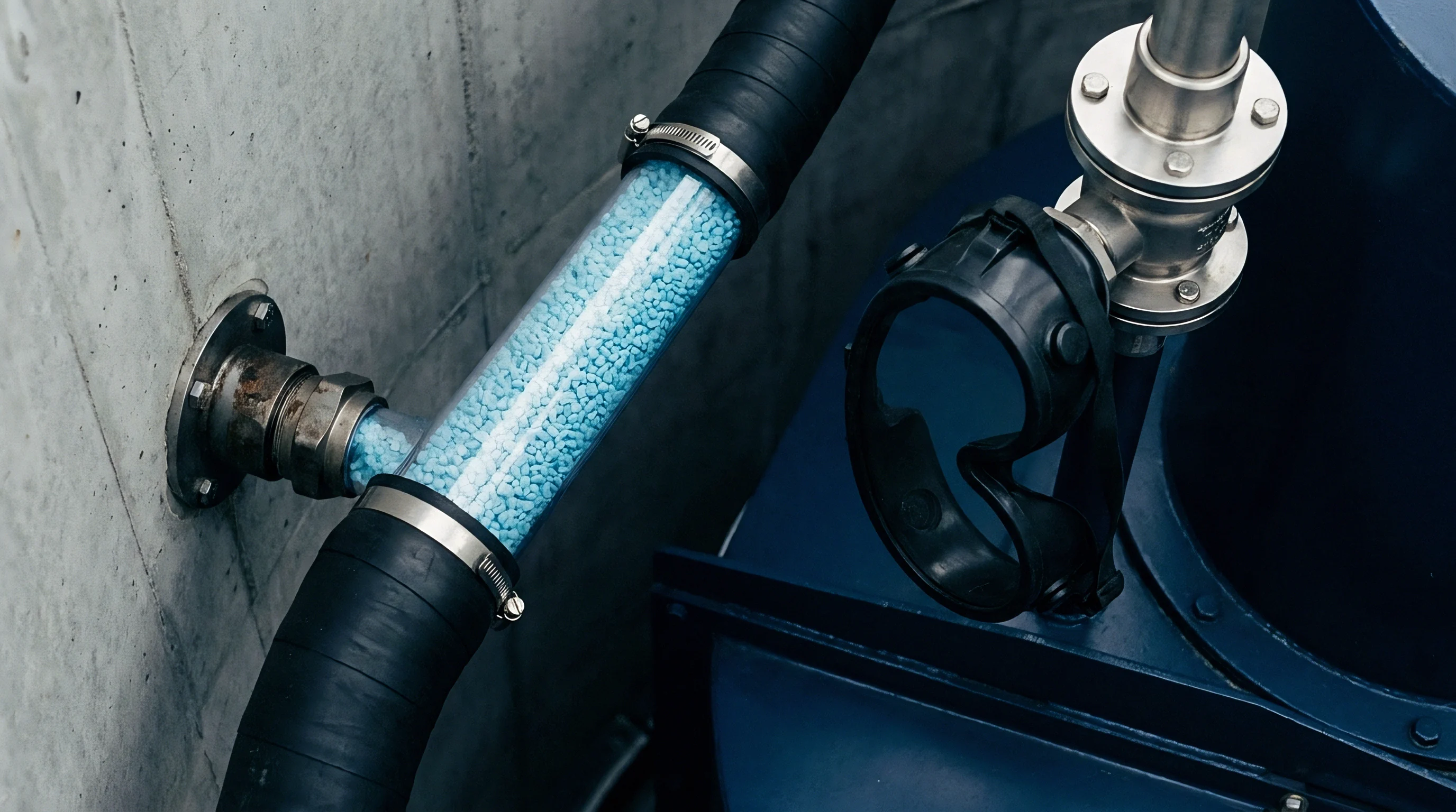

Manifold
Moving an active hot runner tool between international plants requires evaluating the thermal block, melt channel geometry, and gate sealing interfaces. Melt flow inside a heated distribution block depends entirely on thermal equilibrium. Internal flow channels, typically six to eighteen millimeters in diameter, are sized to specific polymer rheology, volumetric flow rates, and shear stress limits.
If the receiving plant operates at different clamp speeds or uses different resin lots, nozzle tip geometry and manifold heater layouts determine whether gate freeze-off stays stable or degrades into stringing and drool.
Steel choice within the distribution assembly controls thermal expansion during heat-up. Alloyed tool steels like H13 or DIN 1.2344 expand predictable fractions of a millimeter per hundred degrees Celsius. Hot runner blocks often rely on titanium or ceramic locating buttons to restrict conductive losses into cold tool plates.
If the destination press runs mismatched platen temperatures or irregular cooling flow, thermal bridging distorts the manifold and misaligns nozzle drops with cavity gates. Flow balance across cavities requires uniform pressure drops through polished melt channels, where generous internal radii prevent dead spots where heat-sensitive resins like polycarbonate or polyamide 66 can degrade.
Valve gate actuation introduces mechanical variables during a transfer. Pneumatic pins need clean, dry air at six to eight bar, while hydraulic setups operate at fifty bar or higher. Servo-driven electric valve gates deliver position control to hundredths of a millimeter, but require compatible controllers at the destination plant.
Any misalignment between the backplate cylinder and valve stem causes binding, scoring, and gate leakage. Likewise, uneven thermal expansion between the valve stem steel and surrounding cavity inserts damages nozzle seating, sending molten plastic straight into the heater pockets.
Thermal expansion in H13 tool steel extends an eighteen-millimeter drop nozzle tip by roughly zero point two two millimeters at an operating temperature of two hundred and eighty degrees Celsius.
Nozzle tip selection establishes the thermal gradient between the hot melt stream and cold mold steel. Direct thermal tips stay in constant contact with the cavity gate, demanding tight cooling line placement around the gate insert. Direct sprung tips or tip insulators made of polyether ether ketone (PEEK) or beryllium copper alter heat transfer rates.
Imbalanced gate cooling at the receiving plant shifts gate freeze-off timing, extending cycle times and causing defects like halo marks or surface stress whitening.

Melt Channel Geometry and Gate Interface Characteristics
Flow channel diameters and gate configurations determine shear exposure during cavity filling. Common tip configurations balance mechanical interfaces, shear limits, and resin compatibility differently.
| Tip Style | Mechanical Interface | Maximum Shear Rate | Thermal Conductivity | Resin Suitability |
|---|---|---|---|---|
| Direct Thermal Tip | Threaded Nozzle Body | 40,000 s⁻¹ | High (BeCu / CuCrZr) | Unfilled Polyolefins, ABS, PS |
| Valve Gate Tip | Guided Pin Seal | 25,000 s⁻¹ | Medium (H13 Steel) | Glass-Filled PA66, PBT, POM |
| Edge Gate Drop | Multi-Cavity Radial Block | 35,000 s⁻¹ | High (Tungsten Carbide) | Medical PP, PC, PMMA |
| Extended Torpedo Tip | Press-Fit Thermal Bushing | 50,000 s⁻¹ | Very High (Copper Alloy) | High-Flow Elastomers, TPE, TPU |
Shear heating in narrow drops can raise melt temperature above the zone controller setpoint. When high-shear channels run glass-filled engineering resins, abrasive fibers scour internal runner walls and strip protective plating. Running different injection speeds at the destination facility can drive local shear rates past critical limits, degrading polymer chains and weakening finished parts.
Tool designers calculate shear rates based on volumetric flow through the nozzle orifice. Moving a mold without checking the receiving press barrel capacity and screw speed profile risks poor melt homogeneity.
Insufficient tip seating pressure allows molten resin to bleed into the mold frame plates. Cleaning an encapsulated manifold assembly means complete teardown, chemical solvent soaks, and manual scraping that can score polished sealing faces. Molders check nozzle tip projection with precision height gages during bench assembly, calculating compressed dimensions against thermal expansion charts.
Setting tip height for the wrong mold plate temperature distorts cavity walls, prompting tool rebuilds and unexpected downtime.
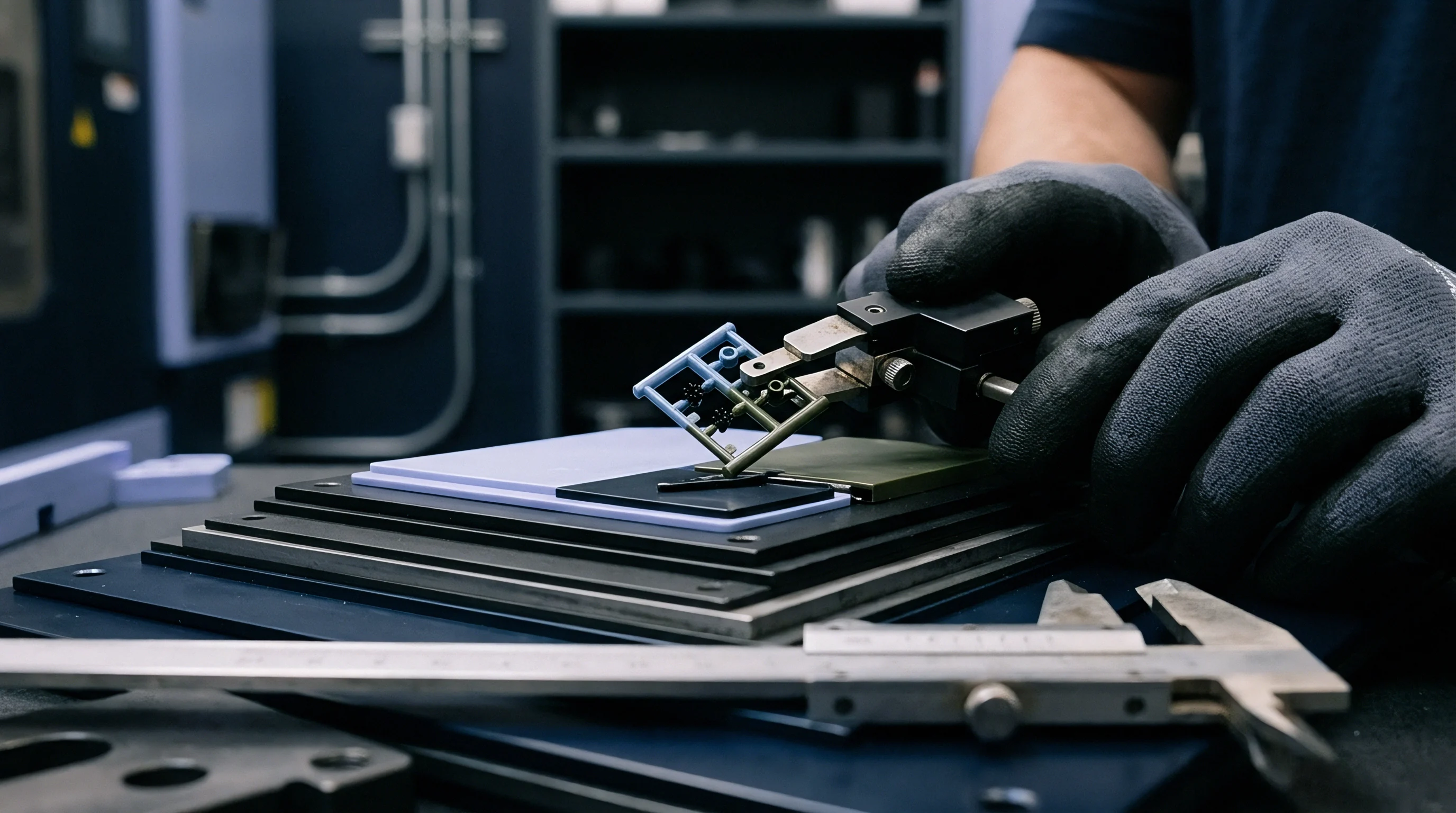
Wiring
Electrical compatibility is a frequent point of failure when moving tooling between regions. Power standards vary significantly across manufacturing hubs: three-phase power runs at two hundred volts in Japan, four hundred volts in Europe, and four hundred and eighty volts in North America. Connectors, pinouts, and grounding must match local temperature control units (TCUs).
Connecting a tool wired for two hundred and thirty volts directly into a four-hundred-and-eighty-volt supply burns out heater bands in milliseconds.
Zone allocation schemes determine how power lines and sensor leads route through heavy-duty connectors. Connector housings from Harting, Epic, or DME use distinct pin numbering for heater leads and thermocouple pairs. Type J thermocouples, using iron and constantan wires, dominate European and American tooling, whereas Type K thermocouples serve higher-temperature applications.
Reversing thermocouple polarity in a wiring harness causes controller temperature readings to drop as the nozzle grows hotter, driving the system to apply maximum power until heaters fail or resin leaks through manifold seals.
Heater elements rely on dense nickel-chromium resistance coils packed in magnesium oxide powder. During ocean transport or extended storage, magnesium oxide absorbs ambient moisture through microscopic flaws in the sheath seals. High humidity drops insulation resistance below safe limits, tripping earth-leakage breakers as soon as line voltage is applied.
Soft-start controller cycles warm damp elements slowly at reduced voltage, evaporating trapped moisture without damaging internal heater wires.
An insulation resistance reading under five megohms at five hundred volts direct current indicates moisture inside magnesium oxide insulation, requiring a controlled soft-start bake-out.
Cold junction compensation in receiving controllers must align with the local grounding scheme. Floating ground loops introduce electrical noise into micro-volt thermocouple signals, causing display readings to bounce. Unstable zone control produces thermal surging in the drops, shifting resin viscosity and shot weight from cycle to cycle.
Grounding straps should tie the tool frame directly to the press frame to discharge static built up by high-velocity melt flow.
Cross-border transfers bring distinct electrical integration risks. Harness integration typically fails along several predictable lines.
- Thermocouple Polarity Reversal causes inverted signal feedback, forcing controllers into runaway heating states that destroy surrounding elastomeric seals.
- Pinout Map Mismatch routes high-voltage heater current directly into sensitive low-voltage sensor inputs, frying controller processing cards instantly.
- Moisture Ingress Failure drops dielectric insulation resistance, triggering main breaker trips upon initial power application at the receiver facility.
- Missing Ground Straps leaves static electricity charges ungrounded, degrading digital temperature sensor signals and risking operator shock.
- Unrated Cable Gauges overheat under high amperage loads, causing insulation melting, short circuits, and localized electrical fires inside conduit channels.
Receiving plants often inherit non-standard wiring from earlier repairs. Wiring color codes differ by region: American ANSI standards use red for negative polarity on Type J thermocouple leads, while European IEC standards use green for positive and white for negative. Technicians auditing incoming tooling should verify continuity at every pin with a digital multimeter before plugging in control cables.
Leaving undocumented wiring modifications off the tool Dossier leaves site engineers guessing during initial press setup.
Universal junction boxes do not automatically eliminate regional compatibility issues during international plant transfers. That assumption overlooks local electrical code enforcement, controller plug variations, and regional line voltage shifts. A tool delivered with non-compliant wiring components stays parked in the aisle until plant technicians rebuild the electrical terminal enclosures.


Window
Establishing a reliable processing window for a transferred tool calls for structured design-of-experiments methodology rather than floor-level trial and error. Viscosity shifts between resin lots produced in different regions alter pressure drop through small nozzle orifices. Scientific molding methods isolate melt temperature, fill speed, hold pressure, and cooling rate to map process limits.
Cavity pressure sensors, mounted behind ejector pins or inside cavity walls, provide real-time data on fill balance across all drops.
Viscosity curves from capillary rheometry show how shear rate changes affect pressure demand in the runner channels. Injecting melt at varied speeds through the hot runner generates a curve that highlights a flat processing region where shear variations barely affect viscosity. Operating in this shear-insensitive zone reduces part weight variation caused by minor hydraulic fluctuations or screw speed drifts.
Setting injection speeds outside this zone magnifies balance errors between inner and outer cavities.
Cavity pressure measurements confirm whether all drops fill uniformly. In a balanced tool, the peak cavity pressure difference between the first-to-fill and last-to-fill cavities stays below ten percent. Uneven nozzle tip clearance, localized heater failure, or scaled cooling lines degrade balance.
Receiving plants weigh parts from every cavity in a single shot, checking standard deviation and range to verify system balance before clearing the tool for production.

When Does Hot Runner Thermal Drift Compromise Cavitation Balance?
Thermal drift occurs when heat builds unevenly across the mold base over long production runs. Conductive transfer into mold plates shifts cavity insert temperatures, altering local cooling rates and resin shrinkage over time. The response of a glass-filled polybutylene terephthalate (PBT) connector housing under DIN 16742 tolerance standards illustrates how drop temperature shifts impact dimensions and part weight.
| Drop Temp Shift (°C) | Peak Cavity Pressure (bar) | Part Weight Variation (%) | Critical Dimension (mm) | DIN 16742 Tolerance Grade |
|---|---|---|---|---|
| Base (260 °C) | 650 ± 5 | 0.00 (Ref) | 24.500 ± 0.010 | TG4 (Precision) |
| + 5 °C Shift | 635 ± 8 | – 0.18 % | 24.512 ± 0.014 | TG4 (Precision) |
| + 10 °C Shift | 615 ± 12 | – 0.42 % | 24.528 ± 0.022 | TG5 (Standard) |
| – 5 °C Shift | 670 ± 10 | + 0.25 % | 24.485 ± 0.016 | TG5 (Standard) |
| – 10 °C Shift | 695 ± 18 | + 0.61 % | 24.462 ± 0.035 | TG6 (Coarse) |
Qualifying transferred tooling demands a systematic bring-up sequence to protect mold steel and verify melt delivery before releasing the process to production.
- Perform cold electrical isolation tests, measuring insulation resistance across all heater zones at five hundred volts direct current.
- Verify hydraulic or pneumatic valve pin stroke using dial indicators attached to the backplate assembly to confirm smooth mechanical travel.
- Connect water manifold lines and verify flow rates exceed Reynolds number four thousand in all cooling circuits to maintain turbulent heat extraction.
- Heat distribution block gradually using soft-start controller profiles to bake out residual moisture from heater elements.
- Verify thermal equilibrium by checking actual drop tip temperatures using external calibrated surface thermocouples against controller setpoint displays.
- Purge barrel and perform initial shot weights at low injection pressure to confirm open flow through all hot drops without gate blockage.
- Conduct an rheological viscosity study by varying injection speed across eight increments while recording peak intensification pressure.
- Perform a gate seal study by measuring part mass across holding time increments to locate the exact time of melt gate freeze-off.
- Collect a thirty-shot continuous sample run at target process settings for dimensional audit against DIN 16742 tolerance specifications.
Gate seal timing dictates when hold pressure can drop without resin flowing back into the nozzle tip. Short hold times cause sink marks, internal voids, and shrinkage beyond drawing tolerances. Excessive hold times overpack the gate area, introducing residual stress that leads to environmental stress cracking later.
Techs weigh parts across incremental hold times to plot mass over time; gate seal is reached when additional hold time no longer adds part mass.
Validating the process window relies on automated data tracking rather than visual checks on first articles. Matching cavity pressure curves against master reference profiles confirms that melt conditions align with original sign-off criteria. Once peak cavity pressure and pressure integrals stay within established control limits, the window is approved for production.
A process window defined by scientific moulding principles transfers cleanly across presses of equal capability regardless of geographical location.
A process window qualified on a press with noticeable platen deflection will fail on a high-rigidity machine. Structural flex in lighter clamps opens the parting line under peak injection pressure, creating flash that technicians often compensate for by lowering hold pressure or dropping melt temperature. That artificial adjustment compromises part density and dimensional stability once the mold moves to a stiffer press.

Crate
Transporting precision tooling across borders exposes polished steel, electrical connectors, and fluid lines to harsh environments. Shipping containers undergo humidity cycles, strong vibration, and temperatures spanning sub-zero conditions up to seventy degrees Celsius. Without mechanical locks and corrosion protection, molds arrive with rusted cavity faces, pitted gate tips, and seized valve pins.
Cooling lines present a hidden risk during long transit. Trapped water fosters rapid iron oxide formation and scaling, clogging internal flow circuits. Blowing channels clear with compressed air and flushing with glycol removes standing water.
Threaded brass or high-density plastic plugs then keep ambient humidity out of internal passages.
Vapor Corrosion Inhibitor (VCI) products protect raw mold steel without the thick grease that takes days to clean off before setup. VCI films emit polar molecules that form an invisible monomolecular layer across exposed steel, blocking electrochemical corrosion. Heavy grease applied to hot runner tips can migrate into porous heaters, carbonizing on startup and causing electrical shorts.
Vacuum-sealed VCI bags protect mold plates and electrical components together.
Mechanical locks stop internal components from shifting during transport. Valve pin backplates and core slides must be pinned and secured with rigid steel straps painted bright yellow or orange. Unlocked slides can slam into cavity faces under transit vibration, dulling shut-offs and bending leader pins.
Heavy side latch bars locked across mold plates prevent separation during crane lifts and container transport.
Documenting transport readiness keeps handoffs clear between logistics providers, customs brokers, and plant engineers. A complete tool transit dossier includes several essential items.
- Signed Pre-Shipment Inspection Checklist confirming complete water drainage, grease application, and latch bar installation.
- Comprehensive Electrical Resistance Log recording cold megohm insulation values for every heater zone prior to vacuum packaging.
- Physical Tool Layout Drawing detailing overall mold dimensions, lifting eye bolt locations, center-of-gravity marks, and total dry weight.
- Hot Runner Wiring Schematics detailing zone pinouts, thermocouple sensor types, line voltage requirements, and connector housing models.
- Customs Commercial Invoice declaring legal asset valuation, Harmonized System (HS) commodity codes, and country-of-origin markings.
Customs inspections can create physical risks for packaged tooling. Border agents often cut open VCI bags to inspect mold cavities for undeclared items, exposing cold steel to humid port air. Clear resealing instructions inside the crate lid prompt inspectors to re-wrap the mold and replace desiccant packs before closing the container.
Port delays can leave crates sitting on docks for weeks, exposing internal steel to salt air. Tracking micro-corrosion inside closed manifold drops becomes nearly impossible while sealed crates sit in humid storage.

Custody
Legal ownership, asset accounting, and risk transfer clauses govern tool transfers just as strictly as technical specifications. Injection molds are frequently customer-owned assets housed at contract manufacturing facilities under bailment agreements. Moving a tool across tax jurisdictions demands precise documentation to manage asset transfer rules, import duties, and intellectual property risk.
Bailment contracts state that ownership remains with the buyer, while physical possession sits temporarily with the contract manufacturer. Serial numbers, steel asset tags, and deep-etched markings should identify ownership on outer mold plates. Unmarked tooling risks seizure by creditors or customs authorities during vendor bankruptcy or tax disputes.
Asset depreciation models track tool amortisation against agreed production volumes. If a mold moves before reaching full amortisation, financial settlements must resolve remaining tool balances, spare parts inventories, and modification costs. Calculating landed transfer costs requires balancing freight, duty, and re-qualification expense against unit price savings at the new facility.
Spare parts planning illustrates the commercial sensitivity of tool relocation. Consider a sixteen-cavity tool transferring from Asia to Europe to produce a complex engineering component at five hundred thousand units per year. Provisioning strategies directly alter initial commitment costs and downtime exposure.
| Cost Component | Minimal Spares Strategy (USD) | Full Spares Package Strategy (USD) |
|---|---|---|
| Initial Transport & Customs Duty | $8,500 | $9,800 |
| Spare Heaters, Tips & Thermocouples | $1,200 (2 Drops) | $6,400 (Complete 16-Drop Set) |
| Customs Clearing Fees | $1,500 | $1,500 |
| Unscheduled Downtime Exposure (Estimated) | $24,000 (48 Hours Lost) | $0 (Immediate Replacement) |
| Re-Qualification & T1 Trial Costs | $4,500 | $4,500 |
| Total Initial Commitment Cost | $39,700 | $22,200 |
Minimal spare packages reduce initial freight and duty, but leave the plant vulnerable to long lead times if specialized components fail during startup. Sourcing replacement tips or custom band heaters across international supply chains can take three to six weeks of air freight. Including a complete spares package capitalizes critical replacement parts into the initial shipment, preventing lost press capacity during bring-up.
Transfer agreements require formal T1 sample sign-off at the receiving facility before releasing final vendor payments or shifting volume contracts. T1 samples undergo full dimensional inspection via coordinate measuring machine (CMM) routines, comparing parts against original CAD models and DIN 16742 tolerance grades. Sign-off hands operational responsibility to the receiving plant and releases the former supplier from production warranties.
Standard asset transfer clauses state: “Title to physical tooling, technical Dossier documentation, and specialized hot runner maintenance fixtures remains exclusively with the Buyer; risk of loss or damage transfers to the Receiver upon physical sign-off at the import destination facility dock.”