Transient Heat Transfer in High Cavitation Injection Molds
High-cavitation transient thermal balance requires turbulent coolant flow, conductive insert alloys, and equalized circuit pressure drops across every cavity.

Core
Thermal Flux and Energy Partitioning in Multi-Cavity Tooling
Injecting molten polymer at temperatures exceeding two hundred degrees Celsius into a high-cavitation steel tool initiates a sharp transient thermal boundary condition. The thermal pulse occurs within tens of milliseconds as molten resin fills thirty-two or sixty-four discrete cavities simultaneously. Energy transfers from the polymer core to the cavity boundary through forced conduction during the fill phase, followed by unsteady-state thermal diffusion throughout the packing and cooling phases.
Polymer thermal diffusivity remains low, typically between zero-point-one and zero-point-two square millimeters per second, forcing a steep temperature gradient across the plastic wall section. High cycle rates compress the available time window for heat removal, elevating the surface temperature of core steel inserts above the baseline temperature of the bulk mold plate.
Steel retains heat. During continuous automatic operation at cycle times below six seconds, cavity steel surfaces never return to the inlet coolant temperature. An equilibrium dynamic state develops where the cavity surface oscillates through a distinct thermal amplitude between melt arrival and part ejection.
Higher cavity counts amplify heat dissipation challenges because internal runner trees, hot runner nozzles, and closely packed cavity blocks concentrate thermal energy in the central volume of the tool standard. Heat flows outward from center cavities toward external mold edges at finite rates, creating structural thermal imbalance across the mold face.
| Material Grade | Thermal Conductivity (W/m·K) | Specific Heat Capacity (J/kg·K) | Density (kg/m³) | Thermal Relaxation Time (s) |
|---|---|---|---|---|
| AISI H13 Tool Steel | 28.6 | 460 | 7800 | 1.22 |
| AISI P20 Steel | 29.0 | 460 | 7850 | 1.21 |
| Ampcoloy 940 (Copper Alloy) | 208.0 | 380 | 8700 | 0.14 |
| Moldmax HH (Beryllium Copper) | 130.0 | 420 | 8360 | 0.23 |
Cooling performance depends on the thermal relaxation time constant of the mold insert material. Lower thermal relaxation values allow the mold surface to clear the heat pulse rapidly before the next injection cycle begins. High-cavitation tooling using conventional tool steel without conductive inserts accumulates residual heat in core pins and narrow ribs.
Heat accumulation leads to delayed gate freeze, inconsistent part ejection, and local polymer degradation.

Melt Contact Mechanics and Boundary Resistance
Melt pressure drives physical contact between the expanding polymer skin and the textured or polished cavity wall. During the filling phase, high cavity pressure minimizes interfacial thermal contact resistance, allowing maximum thermal flux into the steel. As the polymer cools and undergoes volumetric shrinkage, internal pressure drops, causing the solidifying shell to pull away from the cavity wall.
An insulating air gap forms at the interface, reducing the local heat transfer coefficient by up to seventy percent.
Part wall thickness variations exceeding zero-point-two millimeters create localized thermal resistance pockets that extend cycle time by up to fifteen percent.
Core inserts experience continuous compressive contact because cooling plastic shrinks directly onto protruding steel pins. Heat transfers far more efficiently through core contact faces than through cavity recess faces. High-cavitation molds producing thin-walled closure or medical syringe barrels suffer from core overheating due to this asymmetry.
Core temperatures climb steadily until core pin thermal expansion causes scuffing against sliding stripper plates or leads to dimensional off-center wall thickness variations.
Ignoring interfacial heat transfer variations across individual cavities leads to uneven volumetric shrinkage, warpage outside DIN 16742 tolerance bands, and premature mechanical wear on ejector mechanisms.
Circuit
Cooling Fluid Dynamics and Flow Architecture
Cooling circuits in high-cavitation tooling dictate the rate of transient heat removal from cavity walls. Heat transfer coefficients within cooling channels depend directly on the flow regime of the heat transfer fluid. Laminar fluid movement creates a slow-moving boundary layer that inhibits energy transfer from the hot channel wall to the liquid core.
Transitioning from laminar flow to turbulent flow increases heat removal capabilities fourfold by constantly refreshing liquid contact at the pipe surface.
Turbulence occurs when the Reynolds number inside the channel exceeds four thousand. Achieving this state requires explicit fluid velocity, fluid viscosity, and internal channel geometry coordination. In complex multi-cavity plates with series-routed lines, fluid pressure drops compound rapidly across multiple fittings and sharp elbows.
High pressure drop starves downstream cavities of coolant volume, dampening the local heat transfer rate.
- Cooling Circuit Circuitry balancing requires parallel manifold loops rather than long series circuits to ensure uniform coolant delivery temperatures across all cavities.
- Channel Hydraulic Diameter sized between six and ten millimeters maximizes turbulent flow potential without demanding excessive pumping pressure from press thermolators.
- Conformal Circuit Paths fabricated via selective laser melting follow complex cavity contours, maintaining equidistant placement between water and melt.
- Coolant Fluid Additives like ethylene glycol increase viscosity, which demands higher volumetric flow rates to maintain identical Reynolds numbers achieved with pure water.
Conformal cooling channels built into powder-bed additive inserts alter transient heat removal physics. Internal lines track intricate cavity profiles at uniform depths, eliminating thermal dead zones inherent to straight gun-drilled channels. Uniform wall distance suppresses thermal gradients across complex geometric features like internal threads, deep snap fits, and structural ribs.
Pressure Drop Management across Multi-Cavity Manifolds
Distributing fluid equally across sixty-four cavities requires rigid fluid manifold engineering. Flow velocity drops when internal pipe cross-sections expand unexpectedly, creating stagnant fluid regions. Tooling engineers specify external flow manifolds with dedicated flow meters and temperature sensors on every circuit leg.
Monitoring individual flow loops prevents unobserved channel clogging caused by mineral scaling or debris accummulation.
Water temperature rises as fluid absorbs thermal energy along its flow path. A series circuit running across eight cavities yields a cumulative temperature rise between inlet and outlet. Cavities adjacent to the circuit exit see warmer coolant, leading to delayed cooling times and higher part dimensions relative to cavities near the circuit inlet.
Suppliers frequently state that increasing pump pressure solves cavitation cooling deficits, despite hydraulic restrictions inside small drillings limiting total volume throughput.

Transience
Cyclic Thermal Oscillations across Rapid Injection Cycles
Dynamic equilibrium inside an active injection mold never represents a static temperature state. Cavity surfaces experience transient thermal cycling during every individual shot phase. Upon melt contact, the cavity skin surface temperature spikes upwards within zero-point-one seconds, approaching eighty percent of the melt delivery temperature.
Heat moves rapidly into the steel backing plate, causing the surface temperature to decay through the packing, cooling, and plasticizing intervals.
Fast cycle times cut the thermal recovery period short. When the tool opens, part ejection releases the thermal boundary load, exposing cavity surfaces to ambient air or brief blown-air clearing pulses. Heat continues to diffuse from deep inside the insert core toward the channel walls.
If the cooling phase ends before the core thermal core relaxes, residual heat accumulates shot after shot. This dynamic leads to thermal drift over the first two hours of a production run.
Standard operating procedures requiring continuous cavity monitoring specify that thermal equilibrium testing must occur only after two hundred continuous cycles at steady state.
Inner cavities located near the central hot runner manifold absorb heat from both the polymer melt and hot runner nozzle radiation. Outer cavities located near the mold perimeter lose thermal energy through radiation and air convection to the surrounding environment. This spatial heat differential establishes permanent thermal offset zones across the mold block.
Is Transient Thermal Drift Distorting Cavity Dimensions?
Thermal gradients across high-cavitation plate layouts directly drive cavity-to-cavity dimensional dispersion. Steel expands predictably according to its coefficient of thermal expansion, roughly twelve times ten to the negative sixth power per degree Celsius for standard tool steel. A twenty-degree thermal imbalance between center cavities and corner cavities shifts steel position across a large mold plate by tens of micrometers.
Ejector pin alignment suffers, leading to pin flash or mechanical galling during high-speed actuation.
Dimensional variance in molded parts matches this thermal pattern. Center cavities operating at higher average temperatures produce parts with higher volumetric shrinkage and smaller final dimensions. Perimeter cavities operating cooler release parts with lower volumetric shrinkage and larger outer dimensions.
Matching part dimensions across all sixty-four positions requires individual zone temperature trimming using dedicated multi-channel water temperature control units.
Does the core steel reach a thermal saturation limit where additional cooling flow yields no further reduction in part cycle time?

Steel
Material Selection and High Thermal Conductivity Alloys
Tool steel choices dictate the thermal efficiency and mechanical durability of high-cavitation inserts. AISI H13 steel remains standard due to its high hardness, excellent wear resistance, and polished surface capability. Its low thermal conductivity of roughly twenty-eight Watts per meter-Kelvin presents a bottleneck for rapid heat extraction.
Core pins and thin walls made from H13 build up localized heat zones that cannot be cleared through conventional gun-drilled cooling channels.
High-conductivity copper alloys offer thermal performance five to eight times greater than H13 tool steel. Beryllium copper alloys like Moldmax HH and copper-nickel-silicon alloys like Ampcoloy 940 conduct thermal energy efficiently out of deep core features. Integrating copper alloy cores into an H13 main cavity block lowers peak surface temperatures during injection and rapidly draws heat into deep internal water lines.
Wear rates on copper components run higher than hard tool steel, requiring hard nickel or titanium nitride surface coatings in abrasive resin applications.
| Circuit Architecture | Manufacturing Method | Average Surface Delta (°C) | Pressure Drop Bar per Meter | Relative Tooling Cost Factor |
|---|---|---|---|---|
| Gun-Drilled Straight Lines | Deep Hole Drilling | 14.2 | 0.4 | 1.0 |
| Baffled / Bubbler Core Lines | EDM & Milling | 8.6 | 1.2 | 1.4 |
| Conformal 3D Channels | Direct Metal Laser Sintering | 2.1 | 2.8 | 2.6 |
| Hybrid Copper Insert Circuit | Braze Assembly | 4.3 | 0.9 | 1.9 |
Thermal expansion mismatches between dissimilar metals inside a mold insert require strict machining tolerances. Copper alloys expand faster than surrounding H13 steel pockets when heated. Incorrect clearance allowances lead to insert distortion, parting line crush, or seal ring leaks under high operating pressures.
Corrosion Mechanisms and Channel Roughness
Cooling channel wall condition alters heat transfer performance over the tool service life. Unconditioned factory water causes rusting, mineral scale deposit formation, and bio-film build-up on raw steel cooling line surfaces. A zero-point-one millimeter layer of calcium carbonate scale acts as a thermal insulator, dropping local heat dissipation efficiency by up to thirty percent.
- Scale Mineral Deposition insulates water line walls, restricting fluid flow channels and elevating transient mold surface operating temperatures.
- Galvanic Alloy Corrosion occurs at copper-to-steel insert boundaries when untreated water acts as an electrolyte, destroying steel pocket sealing faces.
- Cavitation Erosion Wear inside sharp channel turns destroys internal copper piping walls under high fluid velocity conditions.
- Surface Finish Degradation inside 3D printed conformal cooling lines increases flow friction, causing unexpected pressure drops along the line.
Smooth internal channel surface finishes reduce friction factors and limit mineral attachment points. Stainless tool steels like AISI 420 or ESR-melted grades offer improved corrosion resistance, keeping thermal channels clear across millions of production cycles.
A rule of thumb dictates that copper alloy inserts require replacement or re-coating every five hundred thousand cycles when processing glass-filled polymers.
Inserting high-conductivity alloys without balancing mechanical hardness risks localized parting line collapse under high press clamp tonnage.

Verification
Sensors and In-Cavity Process Qualification
Validating transient thermal behavior inside a high-cavitation tool relies on direct physical measurement rather than press-side assumptions. Infrared thermography cameras capture mold surface heat patterns instantly upon tool open, revealing thermal hot spots and side-to-side channel imbalances. Embedded piezoelectric pressure and fast-response surface thermocouples mounted flush with cavity walls record live thermal and pressure profiles during every millisecond of the cycle.
Data logged from cavity sensors reveals the exact instant of gate freeze. Gate freeze occurs when thermal energy extraction drops local polymer temperature below its glass transition or crystallization point at the gate orifice. Once the gate freezes, pack pressure no longer transmits to the cavity core.
Optimizing cooling circuit timing to match gate freeze saves fractions of a second per cycle across large production volumes.
- Mount the high-cavitation tool in the press and bring all water supply manifolds to the specified temperature setpoint.
- Connect multi-channel data acquisition hardware to all embedded cavity thermocouples and mold surface thermal sensors.
- Run thirty continuous molding shots at nominal process conditions to clear atmospheric moisture and purge the barrel.
- Log dynamic thermal profiles continuously across a fifty-shot stability window at full automatic production speed.
- Extract peak surface temperature values and thermal decay rates for every individual cavity position across the block.
- Compare cavity surface thermal decay rates against ISO 294 specification limits to confirm process window stability.
Decoupled molding strategies utilize thermal sensor feedback to control machine transfer from fill to pack phases. Reliable sensor feedback prevents over-packing center cavities while outer cavities remain under-filled, keeping part weight variance across all positions under zero-point-five percent.
Process Window Bounds under ISO Standards
DIN 16742 sets standardized tolerance groups for plastic injection molded parts based on tool quality and thermal process control. Achieving narrow tolerance classes demands that cavity wall temperature variations remain within a tight three-degree Celsius band across the whole molding area. Process windows defined during initial tool trials establish allowable fluid flow, inlet temperature, and melt delivery parameters.
cavity surface temperature variance across all positions remains below four degrees Celsius during full automatic production run qualification under DIN 16742 rules.
Quality engineers document thermal balance validation in a comprehensive tooling qualification dossier. Part dimensions from full mold layouts are mapped directly against localized cavity cooling rates to prove process capability. Tool sign-off protocols require formal verification that cooling performance holds across three full shift changes without manual operator intervention.
Contracts governing high-cavitation tool commissioning require written verification that thermal equilibrium occurs within thirty seconds of automatic cycle start following any temporary press pause.

Amortization
Cycle Seconds, Scrap Rates, and Tooling Capital Return
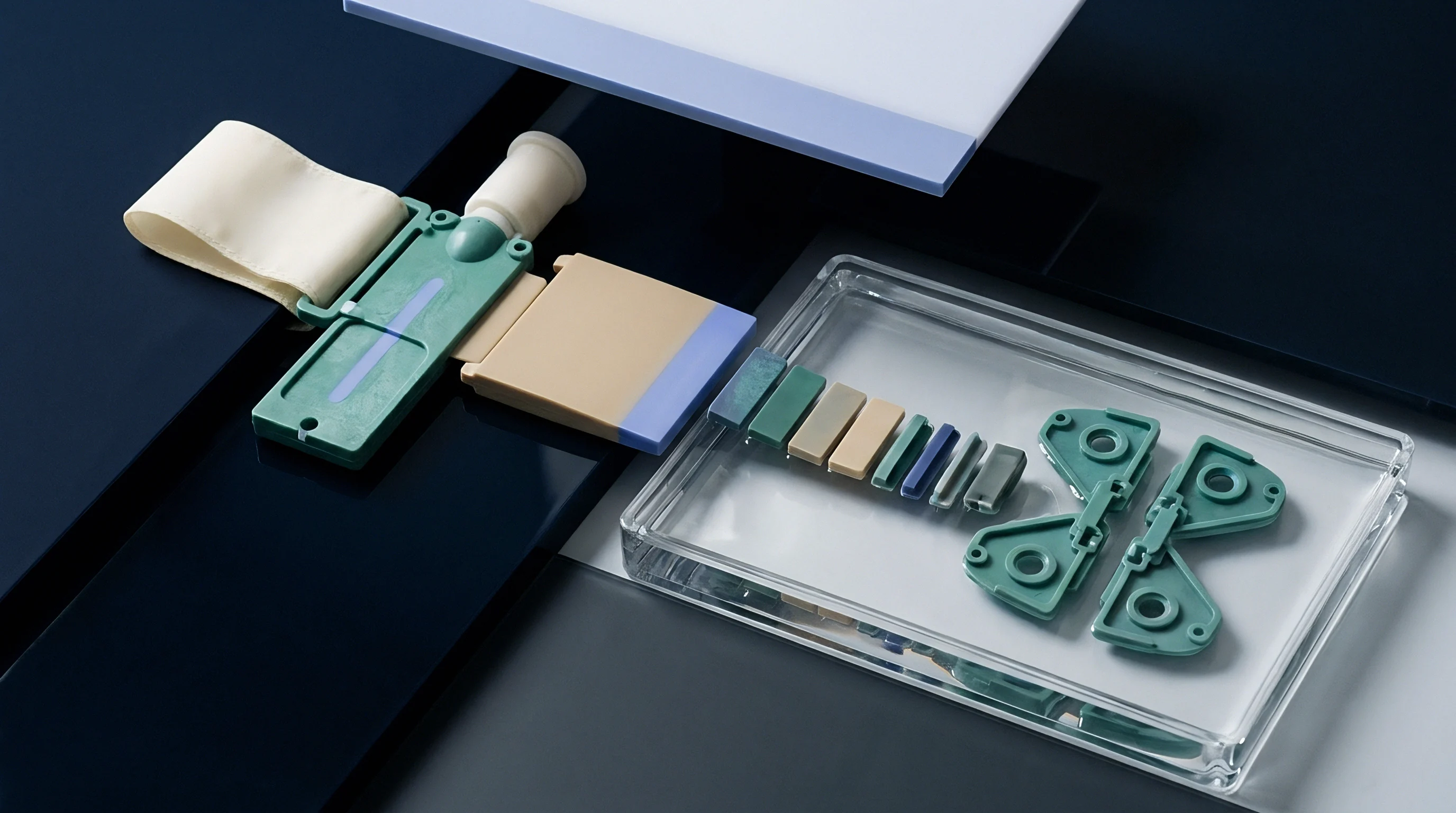
Tooling investments in high-cavitation molds require clear financial justification based on unit production economics. High-cavitation tools demand substantial upfront capital expenditure due to complex hot runner systems, precision insert machining, and conformal cooling components. Reducing cycle time by fractions of a second generates significant financial savings over multi-million-part production runs.
A half-second reduction in cycle time on a sixty-four-cavity mold running at a four-second baseline increases daily press output by over one hundred thousand units. Higher throughput drops fixed machine-hour allocations per part, directly lowering unit costs. Poor transient heat transfer management extends cycle times, causing capital recovery schedules to fall short of financial payback projections.
| Tool Configuration Grade | Upfront Tooling Cost ($) | Base Cycle Time (s) | Scrap Rate Thermal Offset (%) | Break-Even Volume (Units) |
|---|---|---|---|---|
| Standard H13 Steel / Drilled Lines | 180,000 | 6.5 | 2.4 | 3,200,000 |
| H13 with Copper Core Inserts | 225,000 | 5.2 | 1.1 | 2,800,000 |
| Conformal 3D Printed Steel Inserts | 290,000 | 4.3 | 0.5 | 2,450,000 |
| Hybrid Conformal + Copper Cores | 340,000 | 3.8 | 0.3 | 2,300,000 |
Scrap costs tied to thermal defects represent a major driver of total landed part cost. Non-uniform cooling causes part sink marks, void formation, warpage, and dimensional rejection during automatic optical sorting inspections. Reducing thermal scrap rates from two percent down to zero-point-three percent recovers thousands of kilograms of raw resin annually while maximizing usable machine press time.
Spare Insert Provisioning and Tool Ownership Mechanics
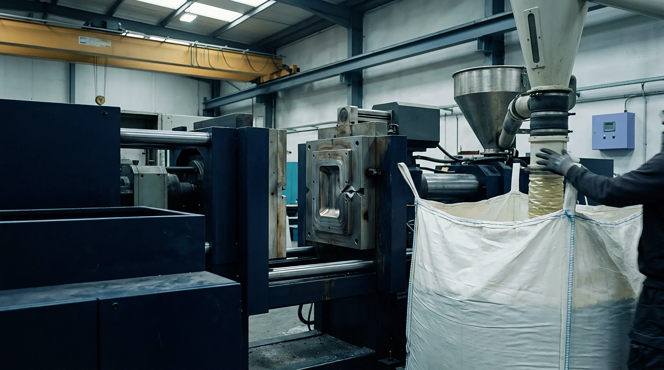
High-thermal-performance tooling architectures require structured maintenance budgets for replacement components. Highly conductive copper inserts experience faster wear and deformation than conventional tool steel blocks. Sourcing contracts for high-cavitation tools specify initial spare part packages, including pre-fitted core pins, fully wired hot runner nozzles, and spare conformal inserts.
Tool transfer agreements define operational maintenance standards and physical asset ownership terms. Molders taking custody of high-performance tooling must maintain water filtration standards to protect internal conformal cooling passages from scaling and clogging. Failure to enforce water quality specifications voids supplier tool life guarantees and shifts financial responsibility for premature insert failure back to the buyer.
Capital amortization schedules track tooling asset depreciation alongside physical shot count milestones. High-cavitation tools running fast transient cycles hit ten million shots within three years of continuous operation, necessitating planned rebuild budgets for core replacement, slide re-fitting, and full cooling circuit chemical flushing to preserve initial heat transfer rates throughout the production lifecycle.