Post Weld Heat Treatment Protocols for Residual Stress Mitigation in Tool Steel Cores
Post-weld heat treatment at 550°C for two hours per inch relieves 85% of peak residual stresses, preventing mandrel cracking and parting line flash.


Bead
A laser-welded H13 injection moulding mandrel extracted after four hours of press operation exhibits severe micro-fissuring along the fusion boundary whenever the shop skips thermal stress mitigation. Toolmakers frequently weld worn shut-off faces, chipped parting gates, and modified core pins using manual tungsten inert gas or automated laser deposition. Laser deposition generates steep thermal gradients.
The surrounding parent steel acts as an aggressive heat sink, quenching the weld pool at rates exceeding one thousand degrees Celsius per second. This rapid thermal cycle transforms the weld metal and the immediately adjacent heat-affected zone into untempered, carbon-saturated martensite. Untempered martensite exhibits extreme brittleness.
Tensile stresses build immediately as the molten puddle solidifies, shrinks against the cold parent metal, and undergoes volumetric transformation.
Without an immediate thermal soaking cycle, residual tensile stresses consistently approach or exceed the ultimate yield point of the base tool steel. Tool steels resist plastic redistribution. The yield point for fully hardened H13 at 48 HRC hovers around 1,400 MPa, meaning subterranean stress spikes of 900 to 1,200 MPa remain locked within two millimetres of the weld line.
When the moulder mounts this mandrel into the press platen, cyclic injection pressures and thermal shock from molten polymer compound these static stresses. Micro-cracking destroys cavity seal integrity. Fatigue cracks nucleate along the interface between the weld filler and the heat-affected parent steel, propagating inward until the core pin shears along the cooling water channel.
Laser wire cladding of AISI H13 tool steel with 1.2343 filler wire generates tensile residual stress spikes exceeding 820 MPa within 0.8 mm of the fusion boundary under ambient deposition.
Mechanical failures in welded tooling cluster into distinct metallurgical patterns governed by local thermal history and restraint conditions:
- Hydrogen Induced Cold Cracking develops in untempered martensitic zones several hours after cooling when trace moisture on the filler wire introduces diffusible hydrogen into the stressed lattice.
- Solidification Shrinkage Tearing occurs along the weld centerline when high-aspect-ratio weld passes freeze inward from the flanks, concentrating volumetric contraction strains into a liquid film.
- Thermal Fatigue Heat Checking accelerates during moulding runs because elevated tensile baselines lower the threshold for cyclic plastic strain caused by alternating polymer melt injection and water chill.
- Interface Delamination separates the added metal from the substrate under side-action shear loads when severe hardness differentials create a mechanical notch across the fusion plane.
Preheating suppresses martensitic transformation shocks. Elevating the entire core insert to three hundred degrees Celsius before striking an arc retards the cooling curve, shifting the transformation temperature below the critical cracking window. Skipping preheat commits the tool to catastrophic internal micro-voids that no subsequent oven cycle can heal.
Omission of the thermal equalization step yields micro-cracking across the fusion line during initial press clamping, scrapping the cavity insert before production begins.

Cycle
Thermal stress relief schedules demand precise furnace control based on the specific metallurgy of the base tool steel and the chemistry of the deposited filler wire. Placing a welded core pin into a cold furnace and ramping at maximum burner output introduces secondary thermal shocks that warp intricate shut-off features. Ramp rates must remain gradual, controlled between fifty and eighty degrees Celsius per hour until the component reaches the stress relief soaking plateau.
Rapid quenching creates localized tensile spikes. The maximum soaking temperature must stay twenty to thirty degrees Celsius below the final tempering temperature applied during the original heat treatment of the tool. Exceeding the original draw temperature permanently softens the bulk core, dropping substrate hardness below specification and destroying wear resistance.
Holding duration at the soaking plateau depends directly on the maximum ruling section of the core insert. Toolmakers calculate one hour of soak time per twenty-five millimetres of cross-sectional thickness, setting a strict minimum soak of two hours regardless of component size. During this dwell period, the elevated thermal energy enables atomic diffusion, permitting locked dislocations to climb and annihilate.
This structural reorganization relaxes residual peak tensile stresses by seventy to eighty-five percent. Double tempering decomposes retained austenite.
Secondary tempering temperatures stay strictly below the original base-tool draw temperature to preserve bulk hardness during thermal stress mitigation.
Retained austenite shifts dimensional baselines. Tool steel grades containing significant chromium, molybdenum, and vanadium retain between five and fifteen percent untransformed austenite in the weld pool after room-temperature cooling. As the core insert cycles during moulding production, this unstable austenite gradually transforms into fresh martensite.
Martensite expands upon phase transformation. This spontaneous volume increase causes unpredicted core pin growth, scuffing slider faces, seizing ejector pins, and inducing flashing across the split lines of the moulding cavity.
| Tool Steel Grade | Base Hardness (HRC) | Preheat Range (°C) | PWHT Plateau (°C) | Minimum Dwell (Hours) | Expected Stress Relaxation |
|---|---|---|---|---|---|
| AISI H13 / 1.2344 | 46 to 50 | 315 to 370 | 540 to 565 | 2.5 | 80% to 85% |
| 1.2343 / ESR | 48 to 52 | 300 to 350 | 530 to 550 | 2.0 | 82% to 87% |
| AISI P20 / 1.2738 | 28 to 32 | 200 to 260 | 480 to 510 | 2.0 | 70% to 75% |
| AISI S7 | 54 to 58 | 260 to 315 | 490 to 510 | 3.0 | 75% to 80% |
| AISI 420 Stainless | 50 to 54 | 230 to 290 | 300 to 320 | 2.5 | 65% to 70% |
Execution of post-weld conditioning follows an uninterrupted sequence of controlled thermal stages designed to prevent structural failure:
- Preheat Maintenance holds the component in an auxiliary chamber at the target welding temperature, preventing interpass temperatures from dropping below two hundred degrees Celsius during manual or robotic deposition passes.
- Immediate Post-Heating raises the core insert directly to three hundred degrees Celsius for sixty minutes immediately upon completing the final weld pass, allowing diffusible hydrogen to escape the steel lattice.
- Controlled Sub-Critical Transformation allows the core insert to cool slowly to eighty degrees Celsius under insulated blankets, ensuring complete transformation of weld austenite into fresh martensite throughout the zone.
- Furnace Stress Soaking heats the assembly at sixty degrees Celsius per hour inside a controlled atmosphere to the designated plateau, soaking the component to dissolve peak residual stresses.
- Programmed Furnace Cooling decreases furnace chamber temperature at forty degrees Celsius per hour down to one hundred and fifty degrees Celsius before opening the door, eliminating thermal contraction stresses.
Soaking time follows thickness while tempering temperature follows base metal toughness.


Furnace
Atmospheric control during thermal processing governs surface chemistry and dimensional stability on polished forming surfaces. Heating naked tool steel cores in an open-air gas-fired oven causes severe oxidation, scaling, and surface decarburization. Decarburization strips carbon from the outermost two tenths of a millimetre, leaving a soft ferritic skin that wears rapidly under abrasive filled resins.
Vacuum furnaces equipped with inert gas backfill systems deliver the required thermal precision while preserving surface integrity. Nitrogen purges prevent surface scaling. Nitrogen blankets suppress surface oxidation during ramp and soak stages, maintaining vacuum levels between 10⁻² and 10⁻⁴ millibar to avoid altering core pin dimensions.
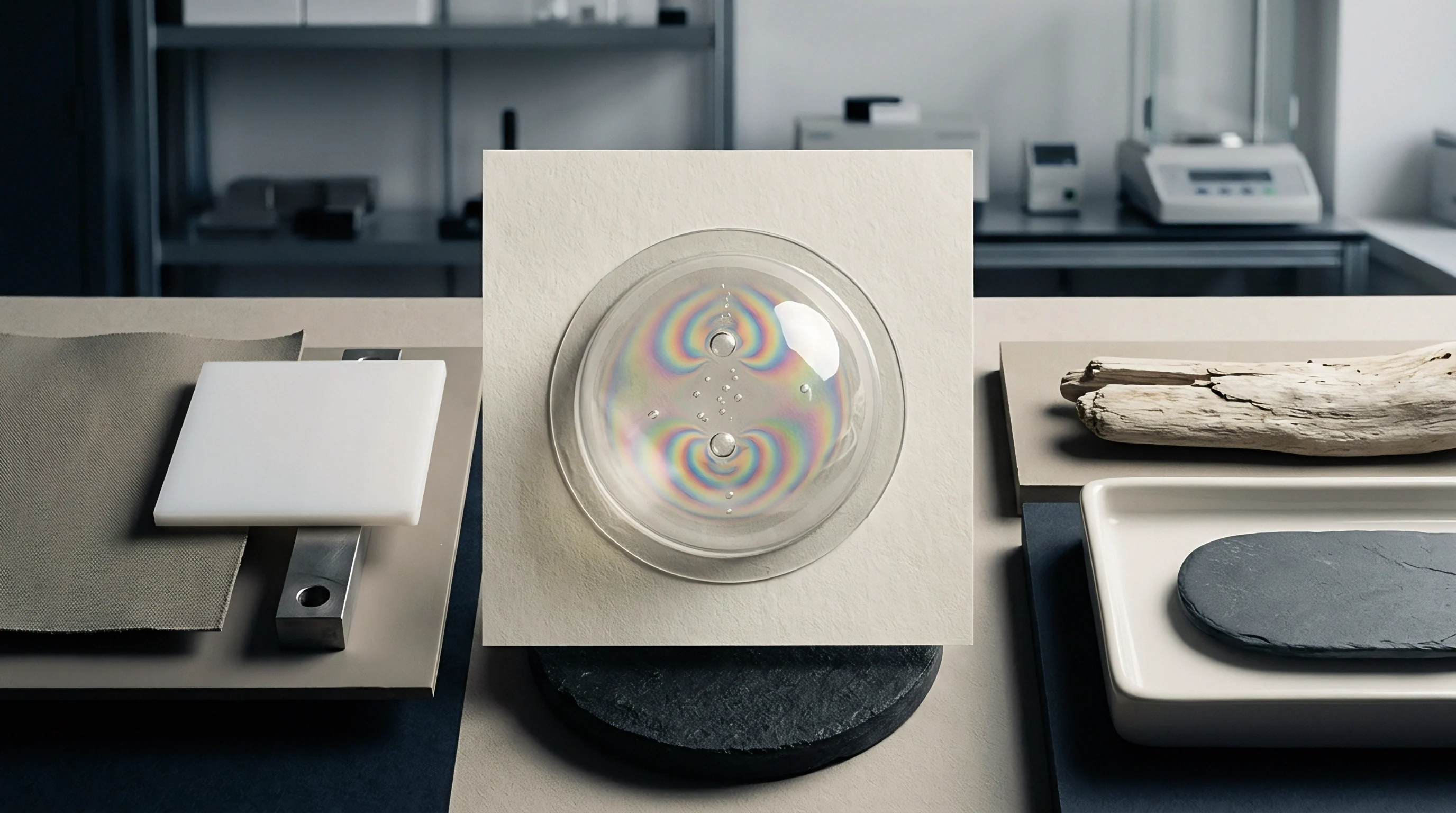
Atmosphere Management and Vacuum Controls
Protective gas atmospheres avoid carbon loss but present specific heat transfer limitations at lower temperatures. Radiant heating in vacuum chambers yields sluggish thermal absorption across tool steel sections below five hundred degrees Celsius. Convection assisted heating, using pressurized high-purity nitrogen backfill at one to two bar, transfers heat evenly into deep blind holes and conformal cooling channels.
Aerospace turbine blade refurbishment programs face identical thermal stress relief dilemmas when laser-cladding nickel superalloys, where uneven heat extraction in thin cooling passages leads to premature thermal fatigue cracking during take-off cycles. Toolmakers face this exact mechanism when restoring delicate cooling circuits inside deep-draw mandrels.
Radiant heating in vacuum chambers yields sluggish thermal absorption across tool steel sections below five hundred degrees Celsius.
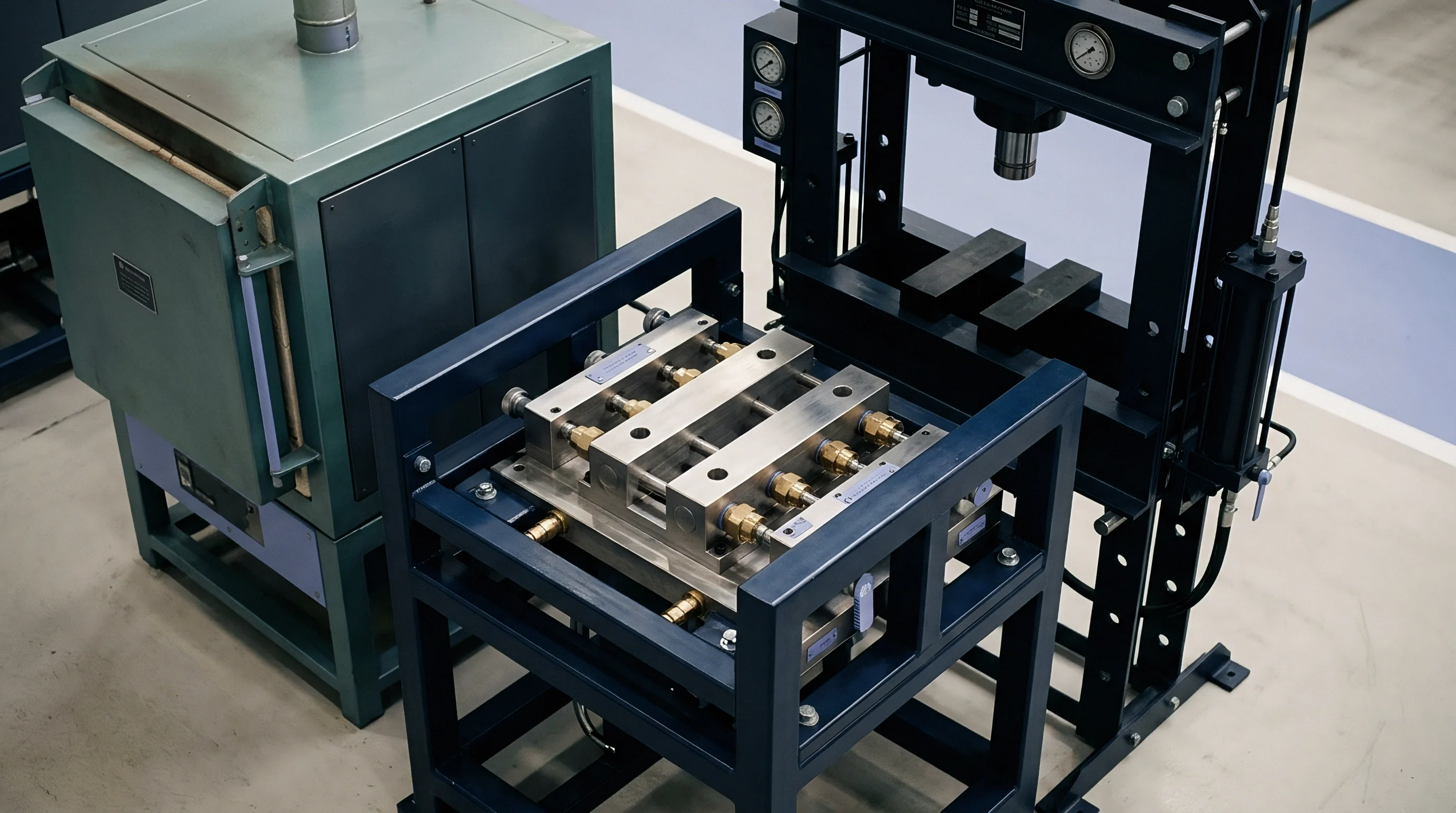
How Does Holding Temperature Govern Stress Relaxation?
Thermal relaxation of residual stresses follows an exponential decay curve governed by the Larson-Miller parameter. At five hundred degrees Celsius, an H13 core insert experiences a reduction in yield strength, allowing residual internal strains to transform into minute, localized plastic deformations. When the soak temperature is set too low, say at four hundred degrees Celsius to prevent any chance of bulk softening, the internal stress reduction stalls at thirty-five percent.
This thirty-five percent relief figure rests on X-ray diffraction measurements documented in European tooling research from 2018 across twelve hot-work steel test specimens; variations in original ingot carbide distribution and vanadium content would shift this relaxation efficiency by up to fifteen percent. Raising the furnace soak to five hundred and fifty degrees Celsius increases the relaxation efficiency to eighty-five percent without compromising core hardness, provided the original temper occurred at five hundred and sixty-five degrees Celsius or higher.
| Furnace Soak Temperature (°C) | Hold Time (Hours) | Peak Initial Stress (MPa) | Post-Treatment Stress (MPa) | Hardness Change (Parent Steel) | Retained Austenite Content |
|---|---|---|---|---|---|
| 450 | 2.0 | 890 | 580 | 0 HRC | 8.2% |
| 500 | 2.0 | 890 | 360 | 0 HRC | 5.4% |
| 540 | 2.0 | 890 | 170 | 0 HRC | 1.8% |
| 560 | 2.0 | 890 | 135 | -0.5 HRC | 0.6% |
| 580 | 2.0 | 890 | 95 | -3.2 HRC | 0.1% |
| 600 | 2.0 | 890 | 60 | -6.8 HRC | 0.0% |
| Data measured via laboratory X-ray diffraction at 0.5 mm depth from fusion boundary; bulk hardness monitored on adjacent parent metal blocks. | |||||
Thermocouple placement dictates soaking accuracy. Attaching contact thermocouples directly to the heaviest section of the core mandrel avoids premature dwell timing triggered by furnace zone sensors. The heat treater claimed that surface discoloration proved adequate soaking despite zero furnace data logs.

Drift
Geometric distortion during thermal stress relief presents an engineering challenge when working with tight mould tolerances. Toolmakers frequently face a trade-off: leaving residual stresses in place risks catastrophic tool fracture, while applying full thermal relief induces dimensional movement that exceeds machining allowances. Core pins bow under unbalanced contraction.
Long, slender mandrels with asymmetric weld deposits on one face warp toward the weld deposit due to volumetric contraction. As the furnace relieves locked-in stresses, the core mandrel relaxes into an unconstrained geometric equilibrium, shifting centerline alignment by twenty to eighty microns.
Mitigating this physical movement requires deliberate pre-weld machining strategies and symmetrical clamping. Experienced tool designers leave 0.15 to 0.25 millimetres of grinding and electrical discharge machining stock on all critical shut-off surfaces before welding. The shop welds the repair zone, applies the complete preheat, post-heat, and furnace stress relief cycle, and only then performs final precision wire EDM or hard milling to net shape.
Long mandrels warp under asymmetrical deposits. Skipping this sequence forces the toolmaker to grind hardened, stressed steel, which releases localized stress fields and creates secondary warping across the press platen.
Which Inspection Method Captures Subsurface Residual Stress?
Evaluating subterranean residual stresses without destroying expensive production inserts requires specific non-destructive and semi-destructive testing protocols. Conventional surface hardness checks provide zero quantitative data regarding locked internal stresses. Electronic hole-drilling strain gauge methods, standardized under ASTM E837, offer high accuracy for subterranean stress profiling up to two millimetres deep.
The toolmaker mounts a microscopic strain gauge rosette, mills a precise 1.5 millimetre hole through the center of the gauge, and measures the micro-strain relief as material is removed. The mathematical conversion of strain relaxation into principal residual stresses yields a precise subterranean profile, identifying hidden tensile stress peaks that indicate inadequate furnace soaking.
Hole drilling reveals subterranean stress gradients. Laboratory X-ray diffraction measures surface lattice strain across a depth of twenty to thirty micrometres, detecting whether surface layers sit under beneficial compression or destructive tension. Tooling engineers also employ magnetic Barkhausen noise analysis for rapid non-destructive screening across production lots, detecting stress concentrations through changes in magnetic domain wall motion.
Current field data indicates that fifty megapascals of residual tension reduces core pin fatigue life by approximately twelve percent; this specific correlation represents an estimate derived from press-side scrap logs across multiple production runs, though variations in polymer melt temperature and mould venting restrict fully defensible mathematical boundaries.
Decision criteria for evaluating post-treatment insert integrity incorporate specific physical metrics:
- Maximum Peak Tensile Stress must remain below one hundred and fifty megapascals across the entire heat-affected zone as verified by laboratory diffraction testing.
- Subsurface Retained Austenite levels must not exceed two percent by volume to prevent unpredictable phase-transformation swelling during high-heat moulding cycles.
- Total Indicator Runout across the length of cylindrical core pins must remain within eight microns relative to datum bearing diameters after furnace discharge.
- Differential Hardness Gradients between the deposited weld bead, heat-affected zone, and base metal must stay within three Rockwell C points to avoid mechanical notch creation.
Whether subterranean compressive layers introduced by laser peening survive fifty thousand thermal injection shots remains unresolved across current tooling trials.
Audit
Sourcing organizations commissioning high-cavitation tooling must protect their capital investments by auditing post-weld thermal records before tool sign-off. Toolmakers absorb secondary wire EDM charges. When an overseas toolroom welds a damaged core insert during initial sampling trials, commercial pressures incentivize bypassing the four-hour furnace soak to preserve trial schedules.
The toolmaker re-machines the flash line, polishes the show surface, and runs fifty sample shots that appear visually flawless. The buyer approves the tool, authorizes final balance payments, and ships the mould to the production facility. Two weeks into production, the core pin snaps, halting an entire automotive assembly line at a cost of thousands of dollars per hour.
Purchasing agreements must require formal post-weld certification dossiers for any cavity component undergoing thermal welding modification. This dossier must contain certified furnace temperature-versus-time chart recordings extracted from workpiece thermocouples, confirming ramp rates, soak duration, and cooling curves. Decarburization checks must accompany micro-hardness traverses across test coupons processed alongside the production cores.
Flash lines multiply across the parting plane. Flash lines destroy parting plane tolerances.
Inspection under ISO 6508-1 rejects any tool steel weld zone displaying hardness variances greater than four Rockwell C points relative to the adjacent parent steel.
Financial responsibility for tool modifications must sit clearly within the purchase agreement. Toolmakers routinely absorb the direct labor cost of welding but attempt to exclude post-weld heat treatment and secondary precision re-machining from their rework warranties. When a core insert requires welding due to a toolroom machining error, the vendor bears full liability for both the metallurgical stress mitigation cycle and any subsequent coordinate-measuring-machine verification.
When engineering changes demand core profile modifications, the buyer pays for the thermal processing sequence rather than risking catastrophic tool fracture by authorizing cosmetic weld repairs.
Under DIN EN ISO 17663 Section 6, the heat treatment certificate binds payment authorization directly to continuous furnace thermocouple chart recordings.