Viscoelastic Melt Flow Transient Integral Drift Diagnostics across Multi Cavity Hydraulic Press Tooling
Dynamic cavity pressure integral analysis detects transient viscoelastic flow drift across high-cavity tooling, isolating hydraulic press valve instability.

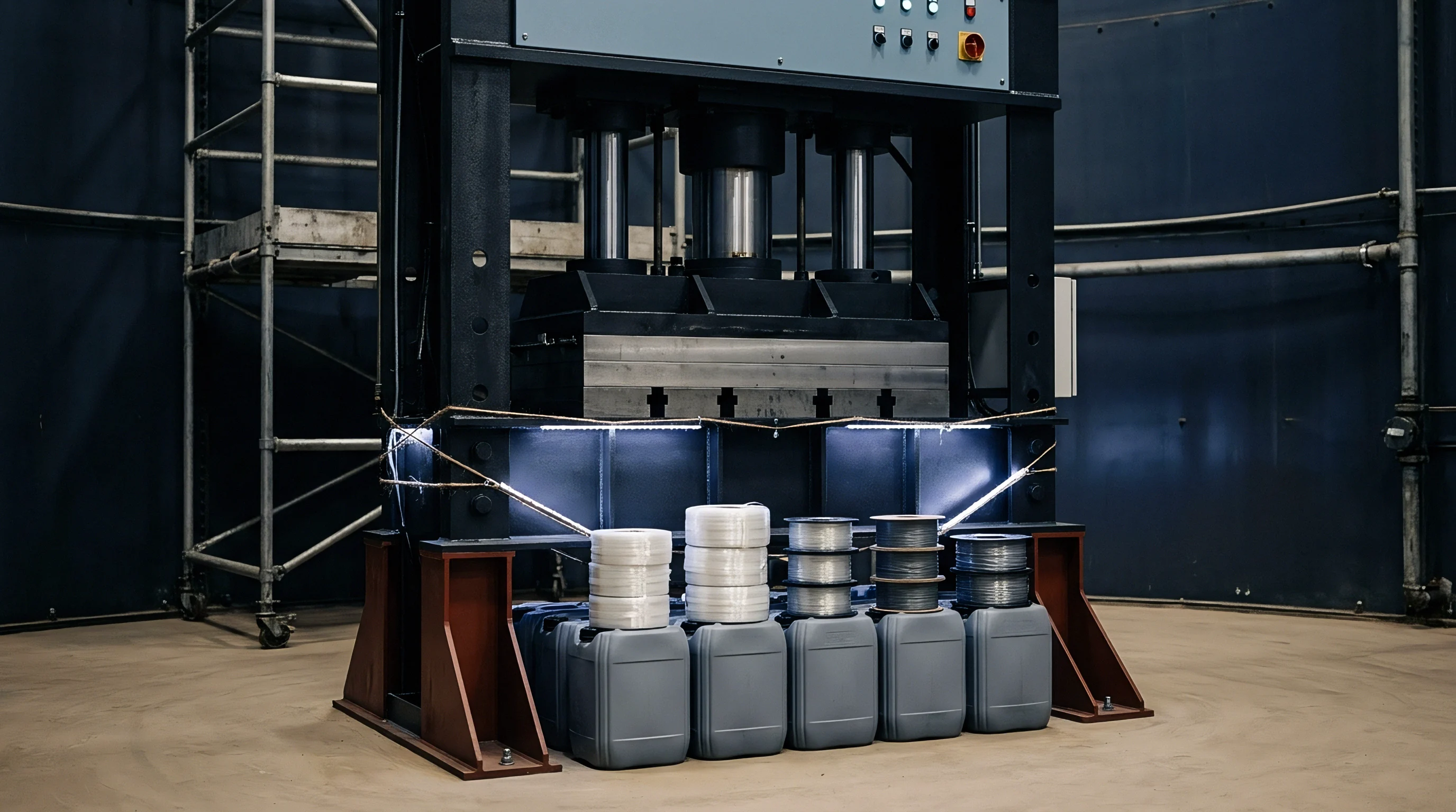
Manifold
Runner layout across multi-cavity tooling establishes the baseline shear history experienced by molten resin before cavity gates open. Geometric balancing on a tool drawing rarely delivers balanced filling at the parting line when processing shear-thinning polymers. Primary delivery channels split polymer melt into unequal shear fields, where high-shear boundary layers travel along interior runner walls while lower-shear cores remain central.
Melt memory dictates volumetric fill. Branching junctions rotate these thermal and rheological gradients, sending hotter, lower-viscosity melt toward specific drops while feeding cooler, higher-viscosity melt into adjacent cavities. The resulting filling imbalance presents as transient velocity differentials across identical part impressions during the high-speed injection phase.
Melt delivery system design determines whether an injection tool maintains dimensional capability under fluctuating factory conditions. Naturally balanced runner layouts dividing an eight-cavity or thirty-two-cavity layout through symmetrical branching trees exhibit shear-induced imbalance because the fluid laminations do not divide symmetrically at consecutive ninety-degree splits. Core polymer entering secondary runners carries the thermal history of the preceding high-shear boundary layer.
Viscous heating distorts runner balance. Drops positioned along outer quadrants receive material with elevated internal temperatures and reduced viscosity, leading to premature cavity filling and higher local packing pressures. Machining runner diameters to artificial offsets compensates for this flow discrepancy only at one specific injection velocity and resin temperature.
- Melt rotation inserts counteract non-symmetrical shear distribution by flipping runner flow laminations ninety degrees before branch splits.
- Direct hot tip geometry reduces runner volume while demanding individual closed-loop PID thermal control for every nozzle.
- Secondary runner transitions preserve laminar boundaries by replacing sharp right-angle intersections with parabolic entry radii exceeding two millimeters.
- Nozzle manifold zoning isolates central feed blocks from perimeter thermal conduction losses through independent heater cartridge circuits.
Feed systems operating under fluctuating hydraulic cylinder actuation amplify rheological asymmetry. Hydraulic press tooling relies on consistent proportional valve response to deliver precise screw velocity profiles during first-stage filling. When hydraulic fluid warms from thirty degrees Celsius at shift start to fifty-five degrees Celsius during full production, valve spool shift dynamics alter by tenths of a millisecond.
The screw velocity drift changes the shear rate inside the manifold channels, altering the degree of shear thinning according to the polymer power-law index. Cavities that filled simultaneously during first-article qualification at low shear begin to experience sequential, staggered gate entry as injection speeds shift under hydraulic drift.
Hot runner manifolds constructed with equal runner lengths frequently display measurable filling time splits between central and perimeter drops. Perimeter drops lose thermal energy to the tool backing plates through structural support pillars, creating localized temperature depressions between three and seven degrees Celsius across outer manifold zones. These thermal depressions shift the local relaxation spectrum of viscoelastic resins, compounding the mechanical imbalance of the hydraulic shot.
Steel dimensions remain fixed. Balancing multi-cavity delivery demands identical thermal profiles and matched shear paths across every individual flow path from machine sprue to cavity gate.
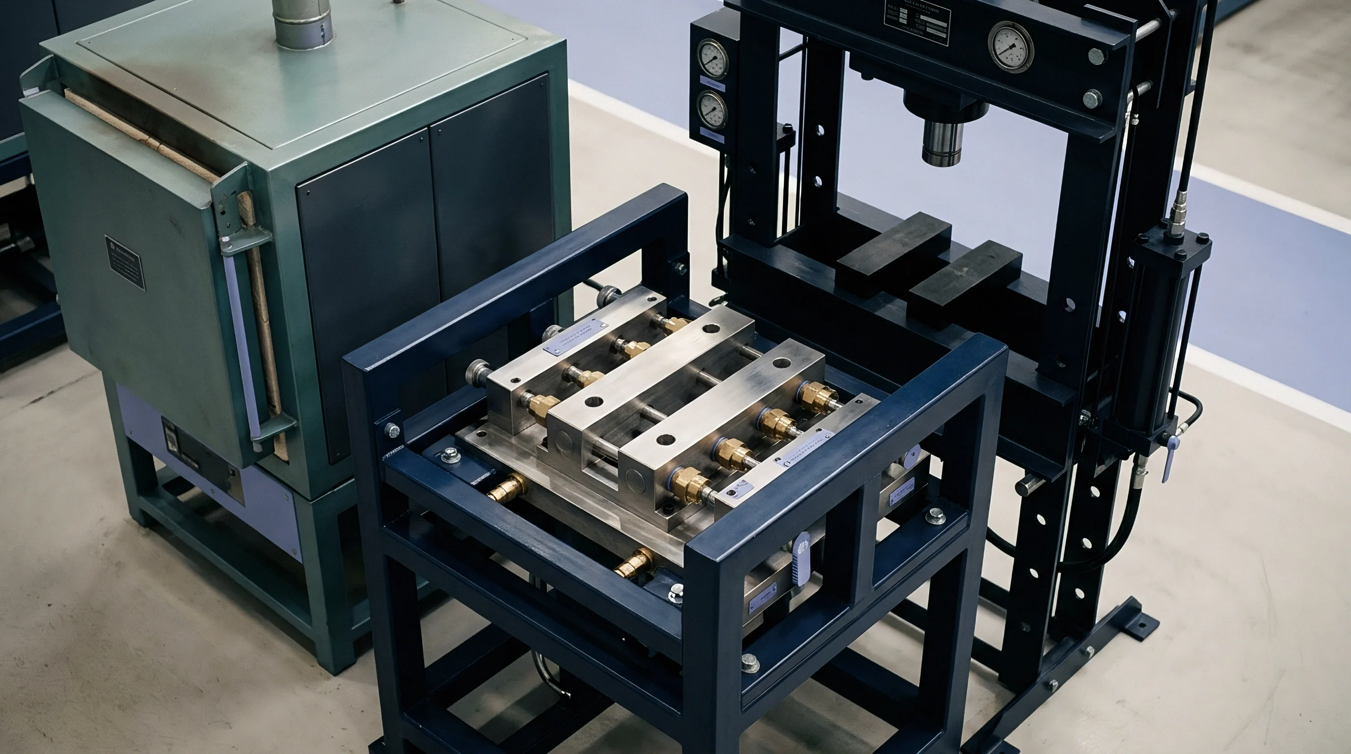
Swell
Polymer chains stretch, uncoil, and align along flow stream vectors when forced through narrow gate orifices under multi-megapascal pressures. Upon exiting the gate restriction into open tool geometry, the stored elastic energy drives volumetric recovery across the melt front. This viscoelastic recovery alters initial cavity wall contact, forming flow marks, localized skin thickening, and variable orientation tensors across separate cavities.
Linear resins exhibiting broad molecular weight distributions store higher elastic energy than narrow distribution grades. Shear history governs molecular relaxation. In multi-cavity configurations, slight shifts in gate approach velocity yield unequal extrudate expansion rates, causing outer impressions to fill with different frozen-in stress profiles than center impressions.
Transient flow drift during hydraulic ram progression directly affects the Deborah number of the advancing melt front, defined as the ratio of polymer relaxation time to the characteristic process flow time. When the hydraulic press experiences valve spool hesitation, the flow rate momentarily decelerates, increasing process flow time and allowing partial chain relaxation inside the runners. Viscoelastic recovery drops instantly.
The melt front enters the cavity with lowered elastic potential, changing the freeze-off timing and shrinkage profile of the moulding. Conversely, rapid machine acceleration spikes the local Weissenberg number, amplifying normal stress differences and generating pronounced jetting or elastic hesitation at thin gate entries.
A hydraulic oil reservoir temperature shift of 8 degrees Celsius alters proportional valve spool latency by 14 milliseconds during high-speed injection.
The first normal stress difference dictates corner filling dynamics and post-moulding warpage. Resins with branched architectures, such as low-density polyethylene or modified polyamides, demonstrate severe normal stress accumulation under high shear rates exceeding ten thousand reciprocal seconds. Tool cavities receiving high-shear melt experience pronounced cross-stream expansion that seals gate lands before packing pressure fully transmits into the part geometry.
Outer impressions freeze prematurely. Part weights from these starved impressions drop, while adjacent impressions fed by lower-shear channels receive sustained packing through prolonged gate freeze windows.
| Polymer Grade Classification | Zero-Shear Viscosity (Pa-s) | Relaxation Spectrum Time (s) | Operating Weissenberg Number | Cavity Drift Sensitivity Rating |
|---|---|---|---|---|
| High-Density Polyethylene (Blow/Injection) | 4,200 | 0.85 | 4.2 to 12.8 | Severe |
| Polypropylene Homopolymer (High Flow) | 650 | 0.12 | 0.8 to 2.4 | Moderate |
| Polyamide 66 (30 Percent Glass Fiber) | 320 | 0.04 | 0.2 to 0.9 | Low |
| Polycarbonate (General Purpose) | 1,800 | 0.38 | 1.5 to 5.1 | High |
| Polybutylene Terephthalate (Unfilled) | 480 | 0.08 | 0.4 to 1.6 | Moderate |
Hydraulic presses lacking high-frequency servovalve feedback cannot arrest the pressure peaks generated when elastic melt fronts encounter internal core shut-offs. Cavity volume constraints convert normal stress recovery into transient pressure spikes that register on machine hydraulic gauges as mechanical clamp resistance. Hydraulic valves react sluggishly.
Toolmakers frequently face complaints that mouldings show flashing along parting lines while simultaneously displaying sink marks above internal ribs. The setter attributes this defect pattern to minor raw material variations between resin lots rather than recognizing transient viscoelastic relaxation imbalances across the tool array.
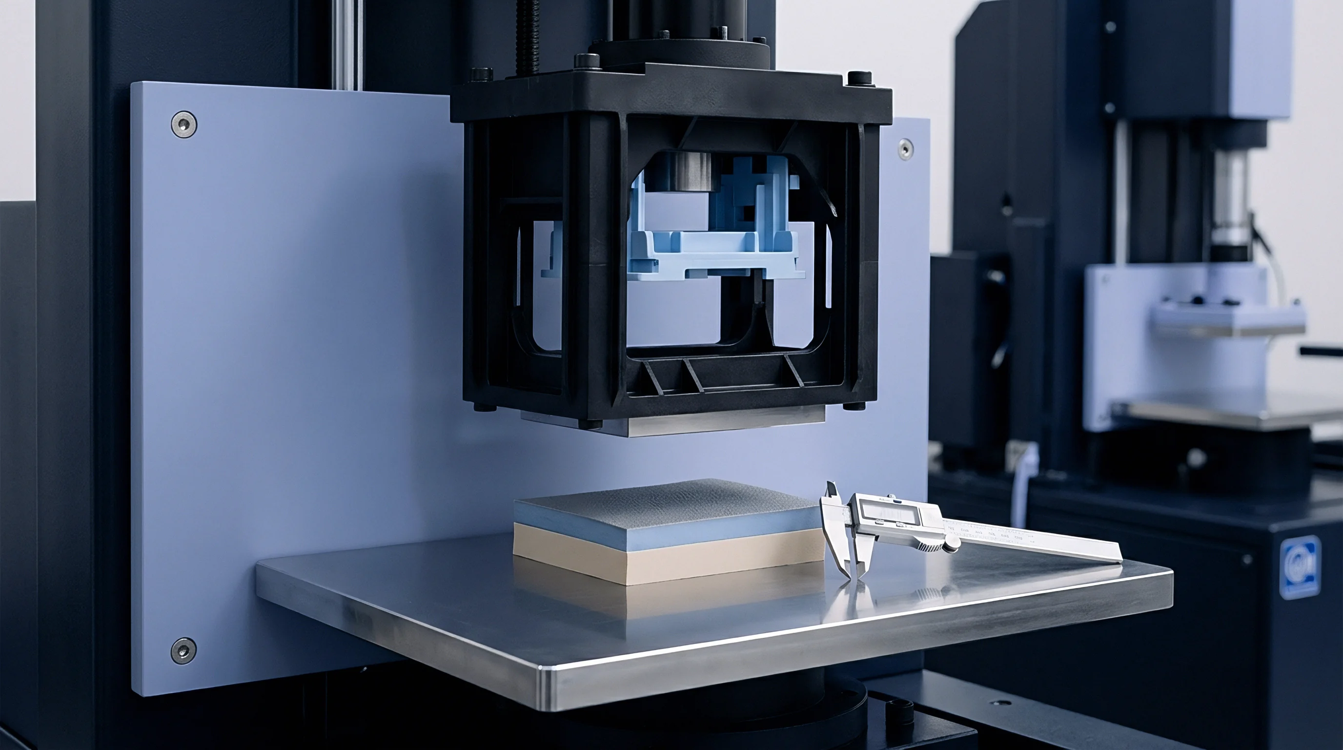

Transducer
Piezoelectric sensors positioned directly behind ejector pins or flush with cavity walls capture dynamic melt flow phenomena that hydraulic line pressure gauges miss entirely. As polymer enters an impression, the melt front contacts the sensor diaphragm, converting mechanical compressive force into an electrical charge proportional to local melt pressure. Integrating this pressure curve over the filling and packing phases generates an operational metric known as the pressure integral.
Viscosity shifts with temperature. Evaluating the pressure integral across all cavities provides real-time verification of cavity balance, exposing subtle transient flow drift long before parts exhibit dimensional failures under optical comparators.

Where Does Hydraulic Transient Drift Accumulate?
Hydraulic injection units exhibit performance fluctuations caused by oil viscosity decay, proportional directional valve hysteresis, and pump compensator reaction times. As hydraulic oil circulates through manifolds and relief valves, its operating temperature rises, dropping oil kinematic viscosity from forty-six centistokes to twenty-eight centistokes over four hours of continuous cycling. This fluid thinning accelerates internal leakage past valve spools and piston seals.
The machine injection carriage struggles to reproduce identical velocity trajectories, causing the switchover point from velocity control to pressure hold to drift forward by several millimeters of screw travel.
Acceptance testing under DIN 16742 Grade TG4 collapses when cavity pressure integral drift across quadrants exceeds three percent during continuous twenty-four-hour production.
Cavity pressure transducers detect this mechanical drift during the dynamic fill interval. In a balanced thirty-two-cavity tool, the pressure integral values for every impression must align within a tight statistical band during stable operation. When hydraulic velocity drifts, impressions located closest to the main sprue experience an instantaneous surge in packing pressure, while distant impressions suffer delayed pressurization.
Sensors detect filling imbalances instantly. A tool with inadequate transducer integration leaves setters operating blind, relying on part mass sorting rather than closed-loop process monitoring to intercept dimensional variation.
- Filling phase integral calculates total energy transfer into the cavity from gate entry to ninety-eight percent volumetric fill.
- Pressure rise derivative isolates the precise microsecond of cavity compaction to identify localized gate freeze anomalies.
- Switchover cavity pressure measures local melt compression at the exact physical moment the machine transitions to pack hold.
- Residual hold integral tracks solidifying skin relaxation during part cooling to predict final ejection warpage.
Consider a production run operating a sixteen-cavity tool producing technical housings in thirty percent glass-filled polybutylene terephthalate. Assume a nominal part mass of 18.50 grams and an injection velocity setting of 65 millimeters per second. Cavity pressure curves across twelve production hours indicate that central impressions 1 through 4 maintain a filling pressure integral of 14,200 bar-seconds with a variation coefficient below 1.2 percent.
Peripheral impressions 13 through 16 display pressure integrals drifting from 13,800 bar-seconds down to 11,400 bar-seconds as hydraulic oil reaches steady-state temperature. The sixteen percent integral drop directly matches a 0.08 millimeter shrinkage variation along the primary mounting boss, shifting the parts outside the DIN 16742 TG4 tolerance boundary.
Machine-side hydraulic transducer readings remain completely flat during these events because total hydraulic pressure averages system resistance across all channels simultaneously. Individual cavity starvation occurs silently under a constant line pressure gauge reading. Overpacking creates severe flash.
Process engineers running high-cavitation tooling without in-cavity piezoelectric monitoring risk shipping millions of out-of-spec components, incurring catastrophic containment, sorting, and warranty recovery expenses.


Variance
Statistical distribution of part dimensions across multi-impression tooling reflects the interaction between machine hydraulic consistency, manifold balancing, and polymer viscoelastic properties. When validating a high-cavity mould under ISO 294 conditions, capability indices such as Cp and Cpk measure within-cavity repeatability against cavity-to-cavity variance. Toolmakers often deliver tools demonstrating acceptable short-term capability across individual impressions while the global tool population fails six-sigma quality standards.
Cycle drift ruins tight tolerances. Transient flow drift widens cavity-to-cavity variance, pushing peripheral cavities toward lower tolerance boundaries while center cavities crowd upper limits.
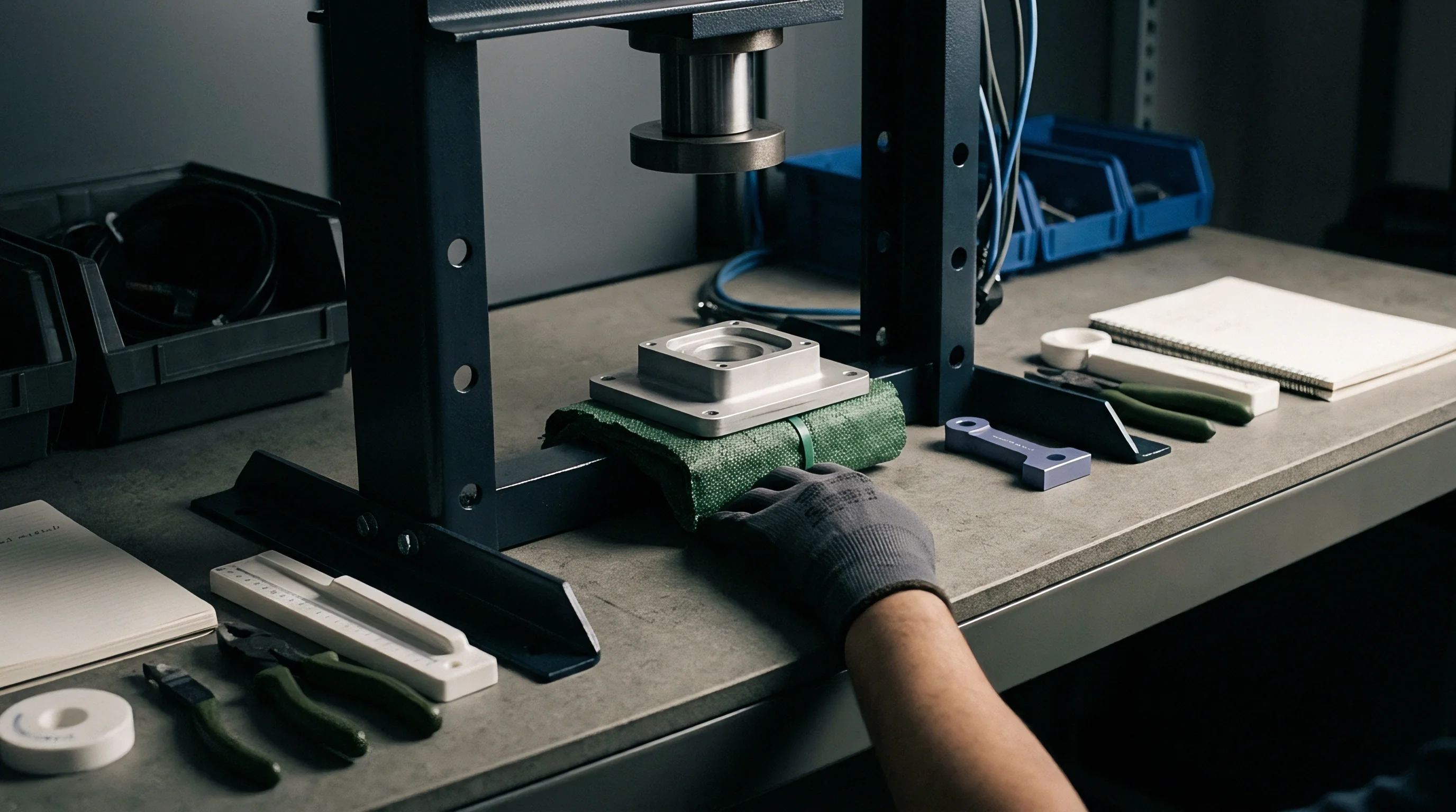
Which Viscoelastic Metrics Isolate Cavity Imbalance?
Dynamic mechanical analysis and capillary rheometry establish the storage modulus, loss modulus, and rate-dependent viscosity necessary to diagnose transient flow drift across multi-cavity tooling. Capillary rheometer sweeps performed across shear rates from one hundred to one hundred thousand reciprocal seconds identify the onset of shear thinning and melt fracture. The ratio of storage modulus to loss modulus defines the elastic storage capacity of the melt.
Cooler runner branches generate elevated wall shear that forces hotter core polymer toward outer tool quadrants. Calculating the relaxation spectrum from oscillatory frequency sweeps reveals whether specific resin lots will clear complex gate geometries without experiencing severe transient flow hesitation.
Cooler runner branches generate elevated wall shear that forces hotter core polymer toward outer tool quadrants.
Verification protocols demand systematic dimensional audits across every impression under stabilized thermal conditions. Tool setters execute gate freeze studies and viscosity curve profiling to identify the stable processing window. Sampling plans must isolate cavity identity across complete production shifts rather than pooling parts into generic bins.
Tracking part weight, critical seal diameters, and wall thickness against cavity serial numbers reveals systematic geographical variance patterns directly linked to hydraulic drift cycles.
- Tool thermal baseline mapping verifies that water manifold cooling channel temperatures vary by less than 1.5 degrees Celsius across all circuit drops using calibrated surface immersion probes.
- Viscosity linearity assessment plots hydraulic line pressure against five incremental injection speeds to verify the Newtonian plateau and power-law transition point before cutover.
- Short shot progression mapping photographs volumetric fill fronts across all impressions at eighty, eighty-five, ninety, and ninety-five percent total shot stroke to identify flow hesitation points.
- Cavity pressure integral normalization adjusts individual hot runner tip temperature setpoints until pressure curve integrals across all cavities converge within three percent.
| Tool Cavity Quadrant | Mean Cavity Peak Pressure (bar) | Pressure Integral Value (bar-s) | Critical Diameter Measure (mm) | Process Capability Index (Cpk) |
|---|---|---|---|---|
| Quadrant 1 (Inner Drops 1 to 8) | 680 | 15,400 | 24.02 | 1.68 |
| Quadrant 2 (Inner Drops 9 to 16) | 675 | 15,310 | 24.01 | 1.62 |
| Quadrant 3 (Outer Drops 17 to 24) | 590 | 13,100 | 23.94 | 1.12 |
| Quadrant 4 (Outer Drops 25 to 32) | 565 | 12,450 | 23.91 | 0.84 |
The tabulated trial data above illustrates a structural problem in high-cavitation tooling. Outer drops in Quadrants 3 and 4 exhibit significant pressure decay, resulting in Cpk values below the minimum acceptable threshold of 1.33 for critical engineering components. Toolmakers frequently attempt to solve this discrepancy by opening gate orifice dimensions with electrical discharge machining.
Enlarging gates permanently alters the steel, masking the underlying hydraulic drift rather than correcting it. Machining steel to resolve flow imbalances locks the mould into a narrow processing window tied to a specific press and an exact ambient temperature range.
The primary technical contention remains whether automated closed-loop valve control can overcome mechanical runner imbalance without requiring mechanical rebuilds. Machine builders argue that millisecond-level proportional valve throttling balances cavity delivery by continuously adapting the injection velocity profile to instantaneous hydraulic oil viscosity. Toolmakers maintain that runner shear distribution cannot be corrected from the press barrel because viscoelastic memory preserves shear history all the way through the gate land.
Rejection costs mount rapidly. Whether machine software or steel modification provides the genuine permanent cure remains an active commercial dispute across the plastics sector.

Settlement
Commercial acceptance of multi-cavity tooling hinges on signed factory acceptance test protocols and verifiable statistical capability across every cavity. Sourcing teams committing significant capital to thirty-two or sixty-four-cavity moulds cannot accept bulk batch sampling that conceals failing impressions behind aggregate population averages. Unbalanced tools bleed manufacturing margin.
A tool that produces five out of spec parts per shot generates scrap rates exceeding fifteen percent over an annual production run of ten million units, destroying piece-part profitability and inflating landed component costs.
Tool supply contracts must specify individual cavity capability thresholds under DIN 16742 Grade TG3 or TG4 tolerances across a minimum continuous four-hour stability run. When peripheral impressions fail tolerance verification due to transient viscoelastic drift, the financial burden of steel modification and press re-qualification falls directly on the toolmaker under clear contract terms. Thermal uniformity preserves dimensional stability.
Tooling purchase orders lacking cavity-specific capability criteria force buyers to accept unbalanced moulds that require constant press-side parameter adjustments by skilled technicians during regular production shifts.
Unbalanced cavity filling forces operators to overpack inner parts to avoid short shots on outer impressions.
Scrap sorting and secondary post-moulding operations eliminate any initial savings achieved by purchasing cheaper, uninstrumented moulds. When multi-cavity tools display severe hydraulic drift, machine operators typically increase holding pressure to force short-shot cavities into spec, overpacking central cavities in the process. Overpacked parts suffer from high internal molded-in stress, leading to environmental stress cracking months after final assembly in the field.
Tool transfer agreements settle accountability. Buyers must protect production yields by mandating comprehensive transient integral diagnostics and certified in-mould transducer data packages prior to releasing final tooling milestone payments.
Commercial contracts governing high-precision multi-cavity tooling must incorporate explicit liquidated damages provisions tied to cavity yield verification under Section 8 of the DIN 16742 standard. These provisions legally obligate the mould builder to absorb all press qualification costs, resin consumption fees, and secondary EDM runner re-profiling expenses whenever cavity pressure integral variance exceeds four percent across thirty consecutive production shots.