Balancing Injection Press Sizing and Cavitation Counts
Optimize injection press sizing and cavitation by matching shot weight to 35-65% barrel capacity and balancing clamp tonnage against peak cavity pressure.

Shot
Injection Barrel Capacity and Thermal Degradation Windows
Determining the correct melt volume per stroke prevents thermal degradation of polymer chains while maintaining consistent pressure transfer into the cavity network. Linear sizing matching barrel capacity to total shot weight governs melt history within the heating cylinder. Optimum processing windows maintain the total swept volume of the injection screw, including the volume of the cold runner or hot runner manifold, between 20 percent and 80 percent of the maximum rated barrel capacity.
Operating below 20 percent barrel capacity extends the residence time of the resin at processing temperatures beyond safe thermal stability boundaries, inducing chain scission, discoloration, and loss of mechanical strength in materials such as polycarbonate or polyamide.
Extended thermal exposure inside the barrel alters polymer viscosity profiles across consecutive machine cycles. High residence times cause thermal degradation that drops the melt flow rate outside specified material bounds, inducing unpredicted flash or incomplete cavity filling. Processing temperature limits for semi-crystalline polymers like polyoxymethylene dictate an upper threshold of residence time beyond which formal resin breakdown releases volatile organic compounds and gaseous byproducts inside the barrel assembly.
Calculating total shot mass relative to barrel volume requires accounting for polymer density in the liquid state, which typically runs 10 to 15 percent lower than solid-state room temperature density.
Maintaining shot weight between 35 percent and 65 percent of total barrel capacity holds melt residence times within a controlled six-minute window for heat-sensitive polymers.
Dosage Precision and Cushion Volumetric Bounds
Accurate dosing depends directly on the ratio of screw diameter to shot stroke. Screw stroke lengths falling below one screw diameter produce inconsistent melt homogenisation and erratic check-ring sealing dynamics. Inconsistent non-return valve seating during the transition from plasticising to injection yields volumetric variations in the delivered melt.
These variations manifest as cavity-to-cavity sink marks, dimensional drift, or short shots across multi-cavity configurations.
Maintaining a stable cushion at the end of the holding phase confirms complete volumetric filling and effective pressure transfer. A residual cushion measuring 3 mm to 6 mm or roughly 5 percent to 10 percent of screw diameter prevents physical contact between the screw tip and the barrel nozzle seat. Excessively large cushion volumes create stagnant polymer zones that degrade over time, while zero cushion condition indicates that holding pressure ceased acting on the melt inside the cavities, causing immediate sink and internal voids.
Resin suppliers frequently assert that processing issues stem entirely from moisture contamination in raw feedstocks rather than thermal exposure during extended barrel residence times.

Tonnage
Peak Cavity Pressure and Project Area Calculation
Calculating the force needed to hold a mould closed against high-velocity polymer melt requires evaluating the projected surface area of all moulded parts and their associated feed system. Total projected area includes the two-dimensional shadow cast by the runner channels, cold slugs, and part geometries onto the main tool parting line. Applied clamping force must exceed the internal hydraulic opening force generated within the tool cavity during peak injection and holding phases to maintain zero gap along the parting line plane.
Peak cavity pressure varies across the runner path based on wall thickness, flow length, resin viscosity, and gate geometry. Thin-wall technical parts demand internal peak cavity pressures reaching 800 bar to 1200 bar, whereas medium-to-thick wall commercial mouldings operate within cavity pressure ranges of 300 bar to 600 bar under nominal processing conditions. Multiplying the combined projected area by the mean cavity pressure determines the theoretical clamping force.
Safety factors between 10 percent and 20 percent are added to counter unexpected pressure spikes during high-speed velocity-to-pressure switchover points.
| Polymer Matrix | Flow Length to Wall Thickness Ratio | Mean Cavity Pressure (bar) | Recommended Specific Clamp Tonnage (kN/cm²) |
|---|---|---|---|
| Polypropylene (Unfilled) | 150:1 to 200:1 | 350 – 450 | 4.5 – 5.5 |
| ABS (High Impact) | 100:1 to 150:1 | 450 – 550 | 5.5 – 7.0 |
| Polyamide 66 (30% Glass Filled) | 80:1 to 120:1 | 600 – 800 | 7.5 – 9.5 |
| Polycarbonate (Unfilled) | 60:1 to 100:1 | 700 – 950 | 8.5 – 11.5 |

Structural Platen Deflection and Parting Line Flash
Excessive clamping force induces physical deformation across machine platens and mould base structures. Machine platens bow under concentrated central hydraulic clamp loads or non-uniform tie-bar strain, transferring non-planar compressive forces to the tool core and cavity blocks. Tooling components subjected to local platen deflection experience parting line wear, micro-flashing at cavity perimeters, and premature failure of core slide interlocks.
Insufficient clamping force permits parting line separation when peak cavity pressure overcomes mechanical tonnage locks. A parting line gap opening wider than 0.015 mm allows melt to escape the cavity boundary, creating flash that demands manual trimming and damages steel shut-off angles over repeated cycles. Balancing clamp capacity against tool footprint dimensions prevents concentrated load points, preserving tooling alignment and cavity shut-off seal integrity over high-volume production schedules.
Standard DIN 16742 mandates that machine platen parallelism remain within 0.05 mm across the entire tie-bar clearance span during full lockup to prevent unilateral shut-off wear.
Selecting an oversized machine frame to guarantee excess clamp capacity escalates machine-hour production costs, increases power consumption per unit mass, and risks crushing small mould bases under excessive surface compression forces.

Balance

Flow Channel Symmetry and Rheological Uniformity
Achieving uniform cavity filling across multi-cavity tooling demands absolute geometric and rheological symmetry throughout the feed system. Naturally balanced runner layouts maintain identical flow paths, channel diameters, and runner lengths from the central sprue location to every individual cavity gate. Flow imbalances in multi-cavity moulds create uneven volumetric packing, causing dimensional variance, weight divergence, and localized warpage across parts moulded within the same machine cycle.
Geometrically symmetrical runner layouts can still experience severe filling imbalances due to shear-induced thermal variations within the polymer melt stream. Non-Newtonian polymer melt flowing through branching runner networks develops high shear rates along channel walls, creating hot, low-viscosity outer layers. When the flow stream splits at a T-junction, these thermal variations divide unevenly between inner and outer cavities, causing inner cavities to fill faster under higher local temperatures and lower melt viscosities.
- Flow Simulation Verification ~ Perform non-linear rheological fill analysis under maximum shear rate conditions to detect non-uniform velocity fronts prior to final tool design sign-off.
- Short Shot Sampling Protocol ~ Execute progressive step-filling machine trials at 50, 70, 80, and 95 percent volumetric filling levels to visually map multi-cavity filling order.
- Cavity Weight Statistical Audit ~ Weigh individual cold parts from a single shot to verify that cavity-to-cavity mass variations remain strictly within a 1.5 percent total window.
- Core Shift Inspection ~ Measure core pin deflections under localized unsymmetrical filling forces to prevent wall thickness variations inside cylindrical part geometries.
How Does Cavity Layout Dictate Injection Pressure?
Selecting linear, H-bridge, or circular cavity arrangements determines the required flow path length and total runner volume inside the mould base. Extended linear layouts increase total melt travel distance, demanding higher injection pressures to overcome viscous pressure drops along the main runner trunks. Elevated pressure requirements force the selection of larger machine injection units and increase peak hydraulic strain across the machine drive assembly.
H-bridge and radial layout structures shorten the melt path from sprue to gate, reducing total system pressure drop during the high-velocity filling phase. Reducing runner length minimizes the volume of scrap material generated per cycle in cold-runner tools and lowers the thermal energy required to re-grind or re-process runner scrap. Optimized runner sizing limits pressure losses while maintaining adequate shear heating to keep the resin flowing without inducing material degradation.
Naturally balanced H-bridge runner networks deliver uniform cavity filling pressures while reducing cold runner scrap volume by up to 30 percent compared to extended linear branching networks.
Layout geometry dictates melt behavior across every gate in the system.

Cycle
Thermal Dissipation and Cooling Channel Proximity
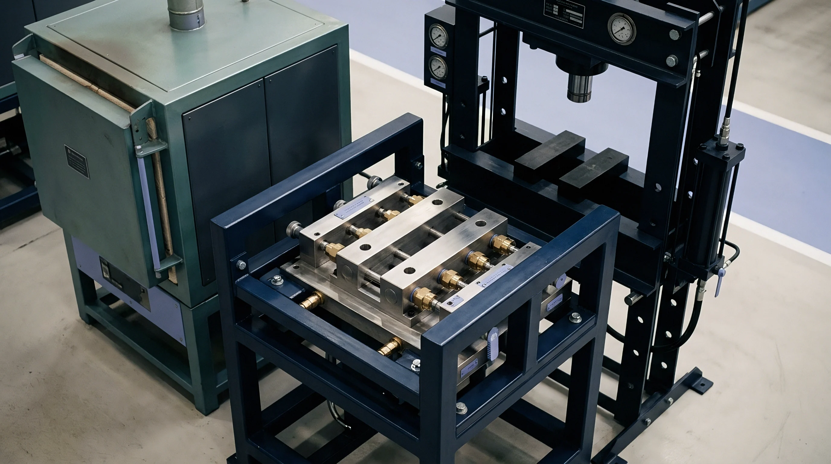
Cooling duration represents the dominant time component within the overall moulding process, accounting for 60 to 80 percent of total dry cycle time. Heat removal rates depend directly on the thermal conductivity of the mould steel, part wall thickness, coolant flow velocity, and the physical distance between cooling channels and the cavity surface. Conformal cooling channels manufactured via additive tooling methods follow complex cavity contours, maintaining uniform distances between steel cooling circuits and plastic interfaces to eliminate localized hot spots.
Thick wall sections act as thermal insulators, slowing heat extraction and extending the required cooling period prior to part ejection. Doubling nominal wall thickness quadruples required cooling time, as conductive heat transport through polymer melt scales with the square of wall thickness. Inefficient heat removal leaves core sections soft upon mould opening, leading to part distortion, ejector pin push-through marks, and post-moulding shrinkage beyond target dimensional drawing limits.
| Cavitation Count | Cooling Time (s) | Dry Cycle Time (s) | Total Cycle Time (s) | Theoretical Output (Parts/hr) |
|---|---|---|---|---|
| 4 Cavities | 6.5 | 2.8 | 11.2 | 1,285 |
| 8 Cavities | 6.8 | 3.4 | 12.1 | 2,380 |
| 16 Cavities | 7.4 | 4.2 | 13.6 | 4,235 |
| 32 Cavities | 8.5 | 5.5 | 16.0 | 7,200 |

Dry Run Hydraulics against Servo-Electric Press Dynamics
Machine dry-cycle execution sets the absolute floor for total cycle time achievable on a given press frame. Servo-electric injection moulding machines deliver precise, simultaneous movement of core pulls, ejector pins, and clamp strokes, reducing dry-cycle overhead times by 1.5 to 3.0 seconds per stroke compared to standard hydraulic units. High-speed clamp actuation shortens non-injecting mold open and close phases, maximizing productive operational uptime within high-cavitation production environments.
Hydraulic machine drives exhibit thermal drift in oil viscosity across multi-shift production runs, altering machine acceleration profiles, valve response times, and clamp buildup durations. Variations in machine dry-cycle times introduce subtle thermal fluctuations within the tool, changing mold surface temperatures and subtly shifting final part shrinkage rates. Electric drives eliminate hydraulic fluid heating variance, maintaining identical stroke velocity profiles across consecutive manufacturing shifts.
What thermal accumulation threshold inside high-density cavity layouts forces an artificial extension of cooling time to protect core pins from bending under mechanical ejection loads?

Amortization
Capital Expenditure Curves and Machine Hour Tariffs
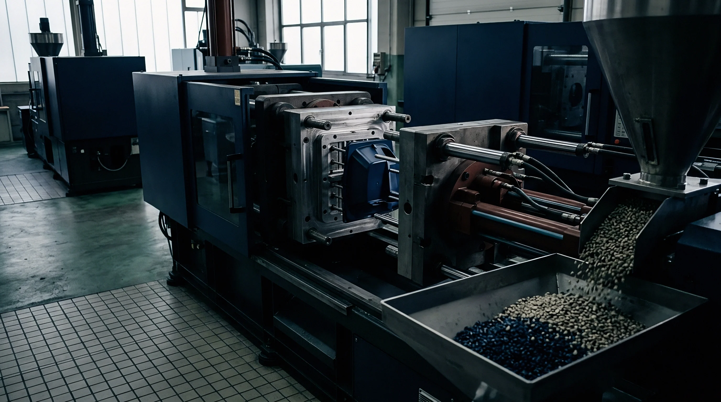
Selecting higher cavitation counts increases initial capital expenditures for tooling while simultaneously reducing machine-hour allocations per finished unit. Tooling construction costs do not scale linearly with cavity count. A 16-cavity tool typically costs 2.2 to 2.6 times more than an equivalent 4-cavity tool, owing to the added complexity of runner manifold systems, precision plate machining, and hot runner temperature control channels.
Larger multi-cavity tools demand larger injection moulding machines characterized by elevated machine-hour rates. Operating a 300-tonne press incurs higher depreciation, electrical power consumption, factory floor space footprint, and maintenance overhead than operating a 100-tonne machine. Balancing cavitation numbers requires matching the amortized tooling cost per part against the hourly running cost of the specific press frame required to run the mold.
| Parameter | 4 Cavities | 8 Cavities | 16 Cavities | 32 Cavities |
|---|---|---|---|---|
| Mould Tool Capital Cost (USD) | $28,000 | $54,000 | $115,000 | $220,000 |
| Required Press Tonnage (Tonnes) | 80 T | 150 T | 300 T | 500 T |
| Machine-Hour Rate (USD/hr) | $35.00 | $48.00 | $72.00 | $110.00 |
| Cycle Time (Seconds) | 11.2 | 12.1 | 13.6 | 16.0 |
| Tooling Cost per Part @ 500k Units | $0.056 | $0.108 | $0.230 | $0.440 |
| Tooling Cost per Part @ 5m Units | $0.0056 | $0.0108 | $0.0230 | $0.0440 |
Break Even Volume Modeling for Cavitation Escalation
Calculating unit piece price across different total production volume targets reveals the precise break-even points where higher cavitation count tools justify their higher initial capital expenditure. Low total order volumes favor lower cavitation counts because high tooling amortization charges dominate the unit piece price sheet. High production volume commitments justify multi-cavity hot-runner tooling because labor and machine-hour cost reductions outweigh the elevated upfront tool procurement cost.
To determine the break-even volume between two cavitation options, calculate the total landed cost by adding initial tooling capital expenses to total operating machine-hour expenditures over a specified production target.
- Determine total required component volume over the projected product life cycle.
- Obtain binding tool fabrication quotes for target cavitation options including guaranteed tool life cycle shot counts.
- Calculate required press clamp tonnage and match against press availability and published machine-hour tariffs.
- Establish true cycle times via thermal simulation or historical empirical benchmark data from similar part geometries.
- Compute landed unit cost at progressive volume milestones to plot the exact capital break-even intersection.
A master supply agreement containing a clear tool ownership transfer clause assigns physical asset titles to the buyer upon completion of the initial capital amortisation phase.
Dossier
Statistical Process Capability and Cavity Uniformity
Evaluating multi-cavity tooling performance requires verifying statistical process capability indices across every individual cavity stream. Assessing overall process capability based on blended samples collected randomly across all cavities obscures cavity-to-cavity variations. Dimensional divergence caused by localized thermal variations or minor steel tolerance imbalances across cavity inserts remains hidden when individual cavity identities are lost in bulk batch sampling.
Calculating separate Cpk metrics for every individual cavity stream isolates specific tooling defects prior to volume production sign-off. Critical functional dimensions must achieve a short-term process capability index (Cpk) exceeding 1.67 during initial tool qualification trials, and maintain a long-term Cpk above 1.33 across continuous manufacturing runs. Identifying a single cavity stream demonstrating a Cpk below 1.33 warrants targeted toolroom adjustments to steel dimensions or local cooling circuits rather than altering machine-wide injection parameters.
Tooling Sign off Audit and Production Transfer Criteria
Establishing formal sign-off acceptance protocols protects buyers from accepting tooling that fails to achieve target cycle times or quality requirements under standard press-side conditions. Qualification dossiers must include complete first article inspection reports, steel measurement certificates, mold cooling flow rate validation traces, and multi-cavity short-shot balance documentation. Machine process parameters established during successful tool trials are logged into a master process sheet to establish the standard processing window for production operations.
- First Article Inspection Dossier ~ Compile full dimensional metrology data covering 100 percent of critical drawing characteristics across all individual cavities.
- Decoupled Process Data Sheet ~ Record fill time, peak hydraulic pressure, plastic pressure, hold pressure transition points, and real coolant flow rates.
- Cavity Identification Verification ~ Confirm that every physical part carries an embossed cavity number matching the layout schematic on the tool drawing.
- Cycle Time Compliance Audit ~ Audit actual sustained run times over a minimum 4-hour continuous production trial to verify compliance with quoted cycle metrics.
Completing these qualification steps ensures that tool construction, machine sizing, and multi-cavity flow dynamics align perfectly with commercial production cost targets.