Real-Time Closed-Loop Cavity Pressure Telemetry Control in High-Cavitation Fast-Cycle Thin-Wall Tooling
Real-time closed-loop cavity pressure telemetry stabilizes part weight and cuts cycle times by dynamically controlling switchover and valve timing.


Piezo
Direct quartz transducers installed behind ejector pins measure force transmission via mechanical contact during filling. Signal fidelity depends on tight mechanical alignment inside the tool steel pockets. In sub-0.40 mm wall sections, pressure spikes push axial forces down slender pin shafts, converting strain to electrical charge at sensitivities near -4.3 picocoulombs per newton.
Fast-cycling, high-cavitation moulds push injection velocities to pressure rise rates above 180,000 bar per second. Wireless or wired telemetry modules in the tool housing must withstand severe thermal cycling and shock loads up to 30 g during mould break and ejection.
Signal degradation lets process drift slip through unnoticed during high-speed runs. Moisture or oil entering sensor pockets lowers insulation resistance, causing charge leakage and signal noise. Meanwhile, high mould temperatures degrade coaxial cable shielding and introduce phase delays.
To maintain closed-loop control, latency through the charge amplifier must stay below 0.5 milliseconds; anything over 2 milliseconds means the controller adjusts injection pressure after freeze-off has already occurred.
Direct cavity transducers running at high acquisition speeds convert local mechanical deflection into calibrated pressure values within 0.3 milliseconds of melt arrival.

Transducer Placement behind Ejector Pins
Pin deflection alters measured force during dynamic filling. Transferring force from melt to sensor depends on the fit between the ejector pin shaft and its bore in the steel core. Standard tooling clearances of 0.008 mm to 0.012 mm prevent flash while letting the pin slide freely.
Tighter fits add friction that absorbs up to 12 percent of the cavity force, causing the signal to underestimate peak pressure in thin-wall cavities.
Indirect mounting behind ejector pins is common in fast-cycle multi-cavity tooling where thin walls leave little room. Direct transducers with flush diaphragms contact the polymer melt directly, eliminating friction losses. These flush sensors present a front diameter of 1.0 mm to 2.5 mm to the cavity and require precise wire-EDM machining to hold surface flushness within 0.005 mm of the cavity wall.
By eliminating pin drag, flush diaphragms capture early pressure transitions reliably.
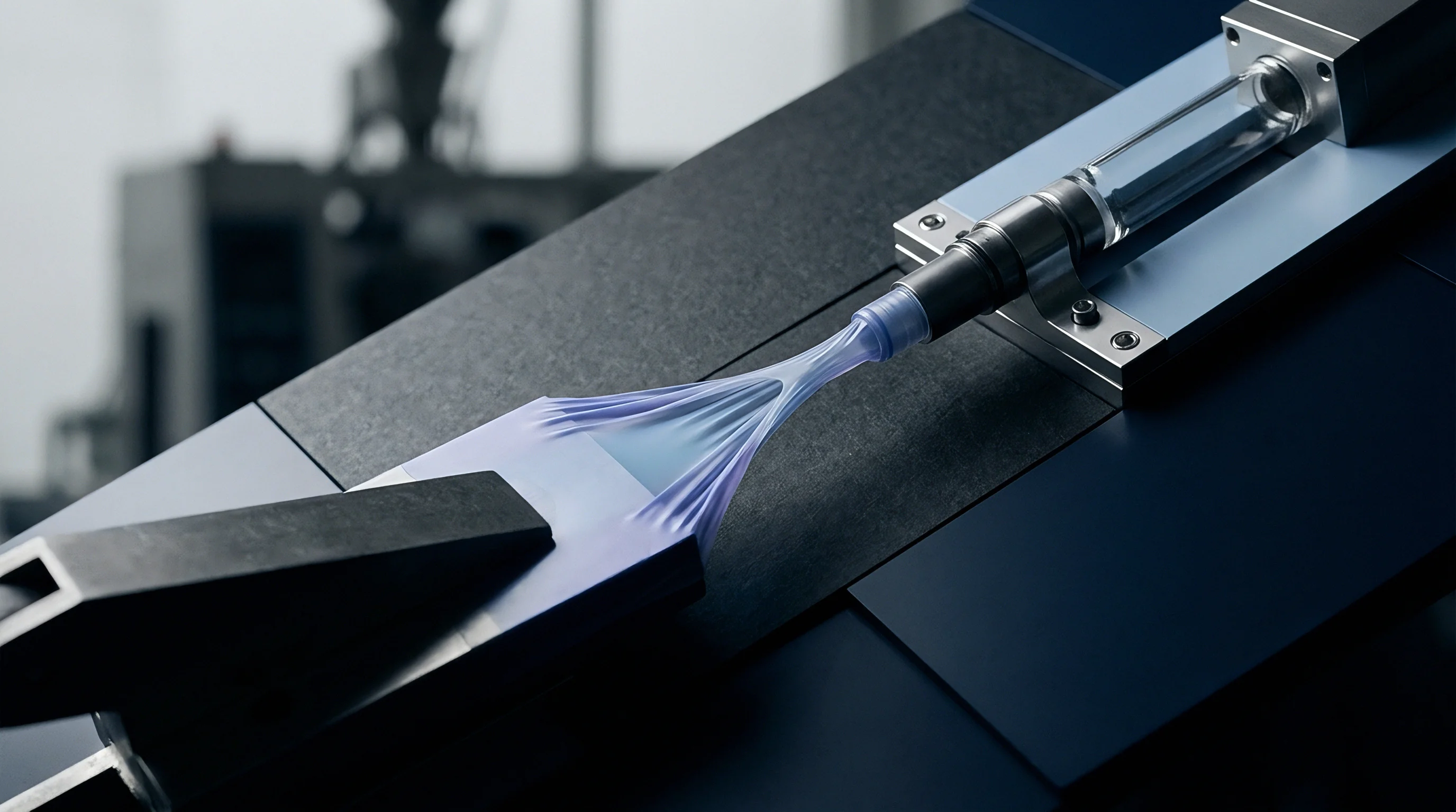
Telemetry Module Integration inside Tooling Plates
Transmitter electronics built into the tool frame route micro-ampere signals away from high-voltage heater bands and servo wiring. Channels cut into the back of machine plates need shielding against capacitive coupling. In 64- or 128-cavity molds, tight wire bundles can cause channel crosstalk that warps pressure traces between adjacent cavities.
Digitizing the signal in a junction box mounted directly on the tool prevents analog signal loss over long cable runs to the controller.
| Sensor Design Type | Response Time | Thermal Limit | Friction Loss Error | Mounting Footprint |
|---|---|---|---|---|
| Flush Quartz Transducer | < 0.10 ms | 300 degrees C | 0.0 percent | Direct cavity face (2.5 mm to 4.0 mm diameter) |
| Indirect Pin Quartz Sensor | 0.30 to 0.60 ms | 200 degrees C | 5.0 to 12.0 percent | Behind ejector pin foot (3.0 mm to 8.0 mm depth) |
| Piezoresistive Strain Gage | 1.20 to 2.50 ms | 150 degrees C | 2.0 to 6.0 percent | Tooling plate recess (10.0 mm x 15.0 mm space) |
| Thick-Film Piezoresistive Sensor | 0.80 to 1.50 ms | 180 degrees C | 1.0 to 4.0 percent | Sub-plate location (5.0 mm clearance depth) |
Sampling rates for closed-loop telemetry must be fast enough to record sharp pressure peaks during rapid injection. Standard controllers sampling at 100 Hz miss spikes that occur within a 15-millisecond fill window. Industrial telemetry cards running at 10,000 Hz per channel catch the melt front hitting the wall, providing pressure derivative curves that pinpoint the exact moment polymer touches the transducer face.
Sensor maintenance tracks insulation resistance over millions of cycles. Heat and resin outgassing leave deposits inside sensor pockets that form conductive paths to ground. If insulation resistance falls below 10 gigaohms, the resulting signal drift shows up as false pressure drops during packing.
Cleaning the sensor pins in an ultrasonic solvent bath restores proper electrical isolation.
Thermal compensation circuits rarely eliminate all temperature-induced zero-point shifts during cold start cycles.

Switch
Velocity-to-pressure transition algorithms govern part density and flash in thin-wall molding. Switching injection modes by screw position or hydraulic pressure causes weight variation whenever melt viscosity shifts between resin lots. Closed-loop telemetry triggers switchover the millisecond cavity pressure reaches setpoint, removing reliance on hydraulic or mechanical repeatability.
During injection, switchover algorithms check pressure traces against target thresholds. Noise or vibration can trigger early switchover if raw signal spikes cross the setpoint. Digital low-pass filtering cleans the stream, though it introduces processing lag.
Edge-detection logic that evaluates the rate of pressure change alongside amplitude stops early triggers without sacrificing response speed.
Standard DIN 16742 TG3 tolerances for thin-wall polyolefin components demand velocity-to-pressure switchover response times below 1.0 millisecond to hold part mass variation under 0.2 percent.

Hydraulic and Servo-Electric Valve Control Latency
Machine response delays distort pressure control loops even when telemetry signals are instantaneous. High-speed servo-electric presses adjust ram velocity within 0.5 to 1.5 milliseconds of receiving a command. Older hydraulic units with proportional valves have delays exceeding 8.0 milliseconds, causing oil pressure spikes that overpack the cavity before ram speed actually drops.
Valve spool acceleration caps compensation speed during ultra-fast fill profiles. Servo-hydraulic systems with spool feedback respond quickly, but oil compressibility inside the cylinder barrel creates a spring effect. As the ram decelerates, thin-wall cavity pressure jumps sharply.
To prevent overshooting target limits, closed-loop algorithms calculate deceleration trajectories in real time and ease the valves back before peak pressure arrives.
Closed-loop systems adjust velocity profiles shot to shot. When regrind lowers batch viscosity, polymer flows faster and reaches sensors earlier in the stroke. Telemetry detects this steep pressure rise and advances switchover automatically, keeping peak cavity pressure steady and part weight consistent despite lot-to-lot melt index changes.
Repeatability requires syncing telemetry triggers with machine mechanics. Any drift in machine response timing moves the packing start point relative to the melt front. Calibrating servo-valve response profiles regularly aligns mechanical performance with digital execution speeds.
A fast closed-loop control system cannot compensate for mechanical delays inherent to slow hydraulic valves.


Balance
Uneven filling in multi-cavity tooling causes dimensional variation and short shots in outlying cavities. Molds with 32, 64, or 128 cavities rely on complex hot runner branch networks, where shear heating shifts create viscosity differences between inner and outer cavity groups. Cavity pressure sensors near end-of-fill locations track arrival times across all cavities and feed balance data back to the press controller.
Dynamic balancing systems adjust individual hot runner valve gates using telemetry data. Sensors detect pressure buildup as melt passes each gate. If outer cavities lag, the controller raises localized nozzle temperatures or adjusts valve pin timing.
These thermal and mechanical tweaks equalize fill speeds across all cavities within three consecutive cycles.

How Does Telemetry Detect Cavity Valve Response Lag?
Pneumatic and hydraulic valve gate actuators suffer from wear, seal friction, and thermal expansion, changing pin speeds across large mold plates. Pressure sensors downstream of individual gates record when melt enters each cavity. Sluggish pins cause delayed pressure rise curves compared to normal cavities.
By comparing pressure onset across channels, the controller flags slow actuators before short shots occur.
In high-cavitation tooling for 0.40 mm caps, a 5.0-millisecond delay in pin opening shifts local filling pressure by up to 140 bar. Such pressure gaps cause flash, sink marks, and inconsistent seal compression across cavity clusters. Logging telemetry data over millions of cycles highlights actuator wear, setting clear targets for valve gate maintenance.
Individual valve gate timing loops fine-tune packing pressure cavity by cavity. Servo-electric systems adjust pin gaps precisely, pinching flow to fast-filling cavities while opening lagging channels wide. Telemetry feedback adjusts pin positions throughout the shot to keep pressure uniform across complex tooling.
- Signal Acquisition Phase ~ Sensor arrays stream cavity pressure data across all active tool channels at 5,000 Hz sampling rates during injection.
- Deviation Calculation ~ The telemetry processor compares real-time pressure curves against a master baseline, calculating volumetric fill timing variations per cavity.
- Pin Stroke Adjustment ~ Servo-electric actuators alter pin tip positions in lagging or leading runner channels to equalize melt flow front velocities.
- Verification and Hold ~ Pressure curves align across all cavities as pack pressure reaches set target levels, locking in uniform part density.
Flow balance drifts as barrel temperatures change or material lots vary in melt flow rate. High shear in thin-wall gates triggers non-Newtonian viscosity shifts that magnify small balance errors. Closed-loop telemetry offsets this shear sensitivity by adjusting flow paths shot by shot to stay within quality limits.
In a 64-cavity thin-wall container tool, cavity-to-cavity pressure variation drops from 18.2 percent down to 2.1 percent when real-time telemetry controls individual valve pin actuation timing.
Unequal cavity pressures require higher clamp tonnage to prevent flash in early cavities, which accelerates tool wear and shortens mold life.


Margin
Thin-wall tooling narrows processing windows because core and cavity steel extract heat rapidly. Polypropylene or high-impact polystyrene injected into 0.35 mm cavity sections drops below freeze-off temperature in under 200 milliseconds. Slight changes in melt temperature or injection speed cause immediate short shots or stress defects.
Real-time telemetry monitors pressure curves to flag drift before parts exceed tolerances.
Processing windows tighten even more as cavitation increases. Dense multi-cavity cooling circuits run complex water lines with local flow restrictions, creating temperature differences across inserts that shift regional cooling and shrinkage. Closed-loop pressure control adjusts packing profiles shot by shot to compensate for thermal variation and hold part dimensions.
Melt viscosity variations exceeding 8 percent root-mean-square instantly exceed thin-wall processing margins without closed-loop pressure feedback adjustments.

Shear-Thinning Polyolefin Rheology in Ultra-Thin Sections
Non-Newtonian behavior governs polyolefin flow through high-aspect-ratio channels. Injection speeds above 500 mm per second create extreme shear rates in narrow cavity paths, dropping apparent viscosity by over 80 percent. Near end-of-fill, shear drops and viscosity climbs rapidly, creating sudden flow resistance.
Telemetry tracks pressure slopes to adjust ram speed dynamically and prevent early hesitation.
| Process Variable | Open-Loop Variation | Closed-Loop Telemetry Limit | Impact on Wall Thickness |
|---|---|---|---|
| Melt Temperature | +/- 8.0 degrees C | +/- 1.5 degrees C | 0.012 mm variation |
| Peak Cavity Pressure | +/- 65 bar | +/- 6 bar | 0.003 mm variation |
| V/P Switchover Point | +/- 0.35 mm ram pos | +/- 0.02 mm ram pos | 0.008 mm variation |
| Cycle Time Consistency | +/- 0.18 seconds | +/- 0.01 seconds | 0.002 mm variation |
High injection pressures can deflect core pins laterally, thinning wall thickness on one side and thickening it on the other. Sensors placed on opposing cavity faces detect pressure asymmetry caused by pin deflection. Telemetry feedback scales back peak injection speeds to keep deflection forces within safe mechanical limits.
Process window studies plot peak pressure against cycle time to establish baseline operating envelopes. Open-loop setups demand tight resin specifications to maintain stability. Closed-loop telemetry widens the operating window, absorbing melt flow index variations up to 15 percent without requiring manual press adjustments.
Will future telemetry sensors withstand continuous exposure to high melt temperatures without requiring frequent recalibration schedules?

Dossier
Tool qualification requires detailed documentation of injection stability over extended runs. Standard statistical process control based on machine stroke position tells you little about conditions inside the cavity. Dossiers built on real-time telemetry record the actual thermomechanical history of every molded part, giving quality auditors verification of structural integrity.
Meeting DIN 16742 TG3 tolerances demands level process consistency that open-loop machine controls cannot deliver in high-volume production. Telemetry systems archive peak pressure, pressure integral values, and fill times for every shot. These files link directly to part serial numbers or lot codes, providing the traceability required in automotive and medical manufacturing.

ISO 294 Calibration Standards and Verification Protocols
Sensor calibration follows ISO 294 guidelines to establish accurate voltage-to-pressure scaling factors. Before installation into tool plates, piezo-transducers are calibrated against load cells in a cleanroom environment. Technicians apply precise hydraulic loads up to 2,000 bar, logging voltage output across rising and falling cycles to quantify hysteresis.
Traceability protocols require regular checks of the signal chain. Field calibration units plug into tool telemetry electronics to simulate charge signals and check controller logic. Verification logs record insulation resistance, signal drift, and channel crosstalk.
These routine runs ensure closed-loop algorithms operate on accurate pressure data during production.
- Transducer Insulation Audits ~ Resistance checks verify charge isolation levels remain above 10 gigaohms across high-humidity manufacturing shifts.
- Signal Line Attenuation Testing ~ Frequency sweeps quantify cable attenuation and electromagnetic interference levels across tool plate junction points.
- Closed-Loop Trigger Verification ~ Controlled pressure steps verify press controller switchover response times remain within sub-millisecond specifications.
- Multi-Cavity Correlation Mapping ~ Data audits compare pressure trace integrals across all active cavities to confirm balanced packing density.
Data storage must handle high throughput from fast-cycling, high-cavitation tooling. A 64-cavity mold on a 2.5-second cycle produces over 1,500 pressure traces per minute. Edge processors analyze pressure curves locally, passing summary metrics and outlier traces to central databases without clogging network bandwidth.
Quality assurance clauses in supply agreements specify that parts moulded during telemetry signal loss events are classified as non-conforming inventory subject to automated scrap segregation.


Ledger
Investing in closed-loop cavity telemetry requires clear returns through lower scrap rates and faster cycle times. Outfitting a 64-cavity thin-wall mold with piezoelectric sensors, internal wiring, telemetry hardware, and press integration cards adds significant upfront cost. That investment has to be offset by operational savings over high-volume production runs.
Faster cycles yield immediate cost gains. Traditional process setups leave generous hold-time margins to guarantee gate freeze across all cavities. Telemetry pinpoints gate freeze by monitoring shifts in pressure decay, telling the controller to start screw recovery as soon as the gate seals.
Trimming 0.3 seconds from a 3.0-second cycle increases annual output on a single machine by 10 percent.
Landed Piece Price Breakdown and Amortisation Mechanics
Tooling amortization spreads sensor integration over millions of components. On a program producing 50 million packaging caps annually, telemetry hardware adds a tiny fraction of a cent per part. Lower scrap rates, raw material savings from stabilized part weight, and higher machine utilization recover those hardware costs within six months.
| Cost Parameter | Open-Loop Base System | Closed-Loop Telemetry System | Annual Financial Variance |
|---|---|---|---|
| Initial Tooling Capital Cost | USD 280,000 | USD 335,000 | + USD 55,000 investment |
| Average Production Cycle Time | 3.10 seconds | 2.75 seconds | 11.3 percent efficiency gain |
| Baseline Process Scrap Rate | 3.20 percent | 0.40 percent | USD 42,000 resin savings |
| Unplanned Machine Downtime | 120 hours/year | 35 hours/year | USD 25,500 press time savings |
| Net Landed Cost per 1,000 Parts | USD 14.80 | USD 13.25 | 10.5 percent unit cost reduction |
Scrap reduction yields substantial savings when running expensive engineering resins or high-grade polyolefins. Open-loop processes waste material during startup thermal stabilization, resin transitions, and ambient temperature swings. Closed-loop telemetry adjusts injection profiles in real time, producing good parts by the second shot after startup.
Material savings come directly from tighter weight control. Containers molded without telemetry rely on thicker target walls to prevent short shots from viscosity changes. Closed-loop pressure control holds part weight to strict tolerances, enabling moldmakers to shave nominal wall thickness by 0.02 mm ~ a change that cuts total resin consumption dramatically over tens of millions of cycles.
Long-term maintenance budgets must account for sensor repair and telemetry cable replacement. Piezoelectric transducers last hundreds of millions of cycles in clean conditions, but mechanical wear and oil contamination eventually require refurbishment. Building sensor maintenance into preventive routines avoids unexpected failures and preserves stability over the tool’s lifespan.
Component buyers increasingly mandate closed-loop telemetry directly in initial RFQ packages. Clear requirements ensure moldmakers design sensor pockets, cable channels, and hardware into the tool from the start, rather than retrofitting after hardening steel. Factory acceptance tests then verify closed-loop response metrics before final mold sign-off.