Evaluating Conformal Cooling Circuit Hydraulics to Reduce Machine Cycle Time
Turbulent flow inside conformal cooling circuits requires managing additive channel roughness and diameter to prevent pump choking and inflated cycle times.
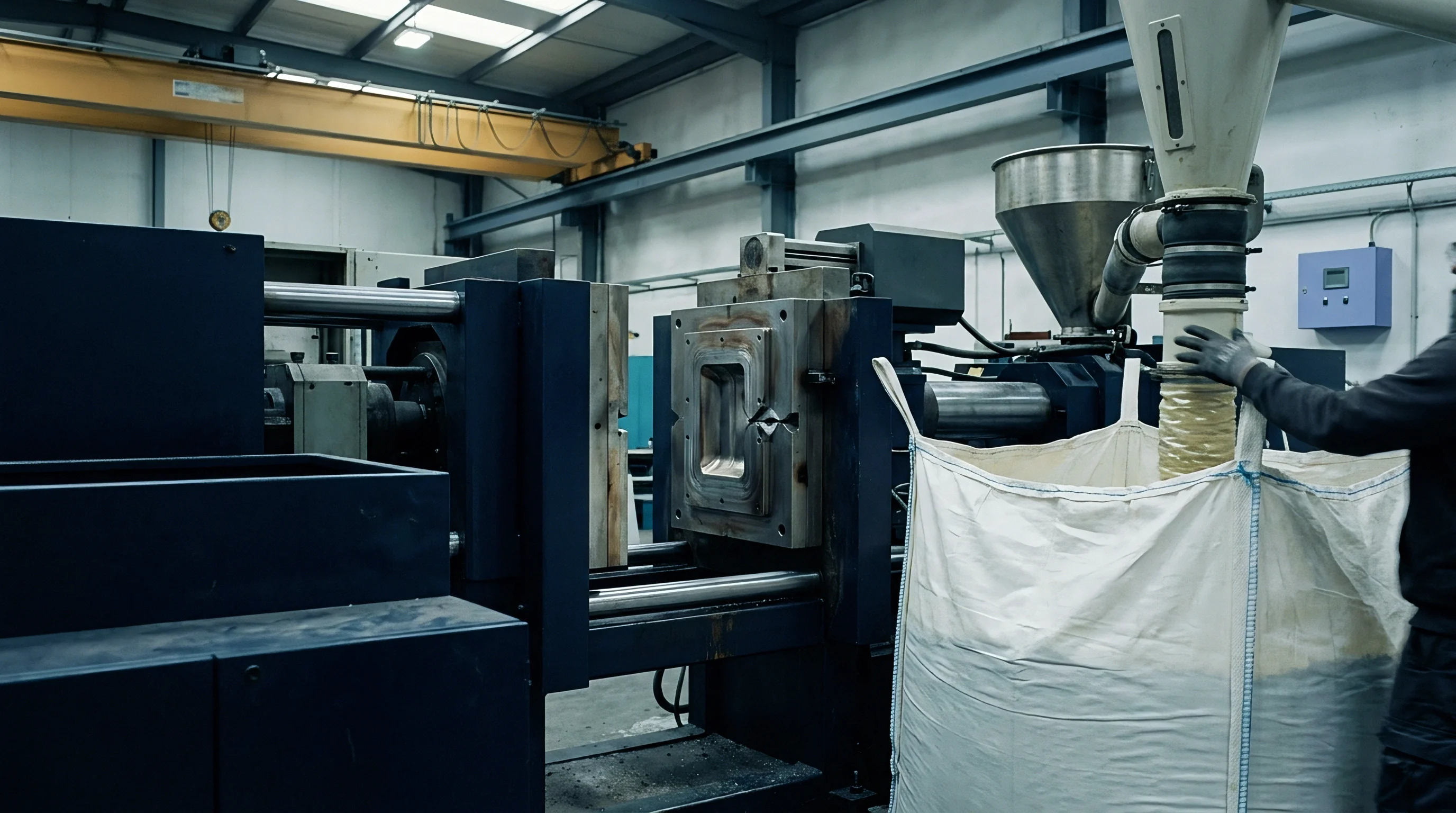
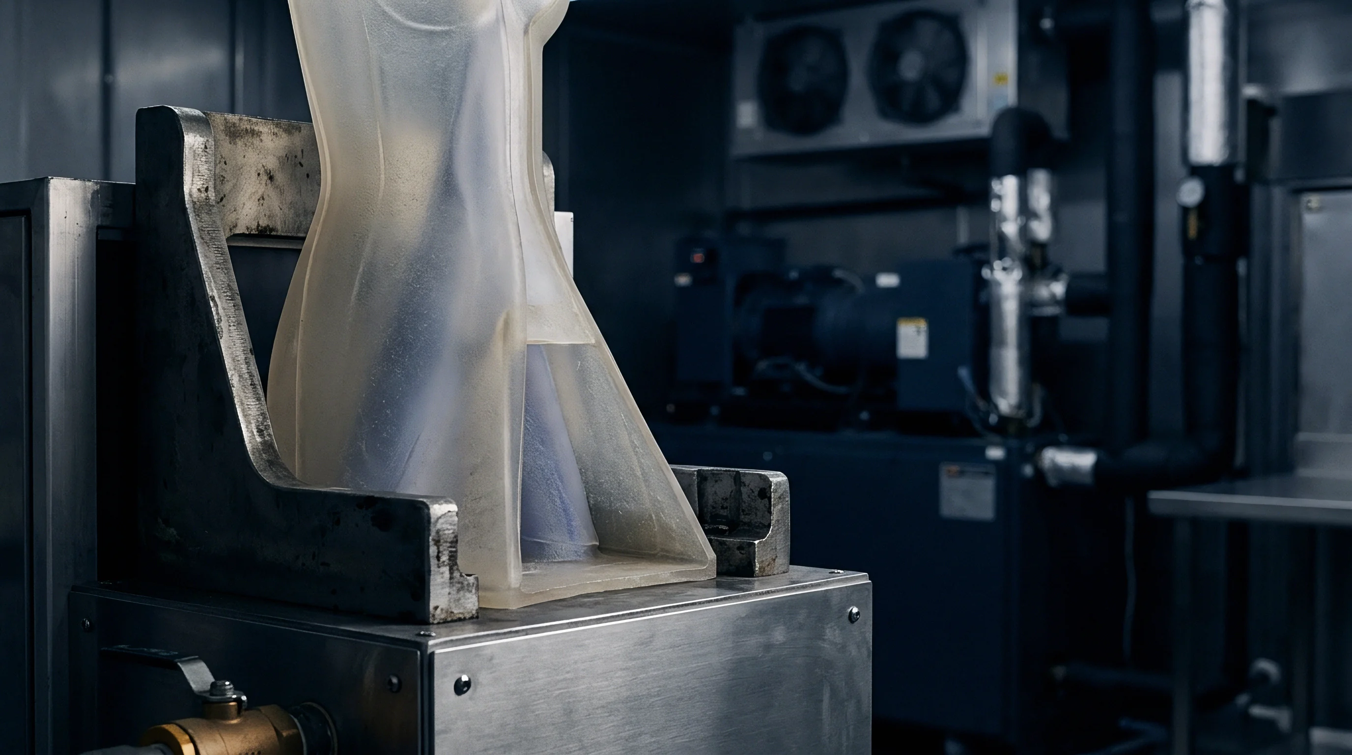
Choke
Tool quotes routinely promise a thirty percent reduction in machine cycle time when substituting direct metal laser sintered tool inserts for gun-drilled tool steel. The quote assumes the chiller unit delivers fluid through the additive insert at the identical volumetric flow rate recorded on the straight channels. Press trials shatter that assumption.
A straight gun-drilled gallery running twelve millimeters in diameter delivers clean Darcy-Weisbach friction factors near 0.02 under standard water temperatures. Conformal passages grown through laser powder bed fusion introduce continuous internal surface roughness between twenty-five and fifty micrometers Ra, alongside tortuous centerline sweeps that double the effective hydraulic length. The resulting head loss starves the cavity of turbulent fluid motion.
Cooling time lengthens, part warpage accelerates, and the machine sits waiting on plastic that refuses to freeze.
Every cooling calculation begins with the Reynolds number inside the cooling passage. Maintaining a Reynolds number above 4,000 ensures turbulent flow, which breaks the stagnant thermal boundary layer against the steel wall and drives heat out of the molten polymer. When friction choke forces the Reynolds number below 2,300 into the laminar regime, the convective heat transfer coefficient plummets from 8,000 W/(m²·K) down to less than 1,200 W/(m²·K).
A moulder compensates by dialing the supply pump to maximum delivery pressure, only to hit the pressure relief bypass on the temperature control unit. The tool absorbs heat, the mold surface temperature drifts forty degrees above setpoint across an eight-hour run, and the quoted twenty-second cycle locks at twenty-eight seconds to avoid ejector pin punch-through.
Water moving in laminar streamlines leaves a static insulating film against rough additive channels, collapsing the heat transfer coefficient to one-sixth of turbulent values.
The hydraulic network within an additive insert behaves like a set of non-linear resistors arranged in series and parallel. Tool designers frequently split an eight-millimeter supply line into four four-millimeter conformal sub-circuits sweeping over deep core ribs. The reduction in diameter increases flow velocity if total volume remains constant, but the required pressure drop scales inversely with the fifth power of the hydraulic diameter.
That fourth-power dependency in the Hagen-Poiseuille relationship, combined with additive manufacturing surface drag, creates an absolute volumetric bottleneck. The tool chokes. Supply water routes through the lower-resistance external manifolds, bypassing the critical rib geometry entirely.
Understanding this hydraulic penalty determines whether an additive insert pays for itself or destroys the operating margin. A toolroom investing twenty thousand dollars in laser-melted Maraging 300 steel inserts needs to verify the fluid circuit long before cutting the parting line. Flow rate dictates cycle time, cycle time dictates press hourly rate amortisation, and press rate governs the piece price submitted to the buyer.
When the fluid mechanics fail, the entire financial thesis of the mould collapses on the shop floor.
One primary standard, DIN 16742, dictates acceptance tolerances for injection-moulded thermoplastics across industrial grades. Part shrinkage scales with mold surface temperature variation. A circuit that starves one side of a cavity produces differential cooling across the nominal wall, inducing internal stress that twists the part beyond Grade TG4 limits into TG6 scrap.
Hydraulic verification establishes the base floor of part dimensional stability.
Pumping equipment encounters strict mechanical thresholds when confronting conformal networks. Standard press-side temperature control units house peripheral pumps rated for a maximum discharge head of 3.8 bar to 5.5 bar at eighty liters per minute. Running an intricate eighteen-turn conformal insert can demand eight to ten bar just to achieve four thousand Reynolds number.
Without dedicated booster pumps or positive displacement units, the tool starves on day one.

Hydraulic Diameter across Additive Build Orientations
Direct metal laser melting produces passages with variable geometry along the Z-axis. Down-facing surfaces inside horizontal cooling channels suffer from un-melted powder adhesion and drooping weld pools, transforming an intended circular cross section of six millimeters into an irregular teardrop profile. The actual hydraulic diameter differs sharply from the CAD file nominal dimension.
Toolmakers who fail to calculate hydraulic diameter via four times the cross-sectional area divided by the wetted perimeter miscalculate their circuit flow capability by up to thirty-five percent.
| Manufacturing Method | Mean Roughness Ra (µm) | Relative Roughness (ε/D, 8mm) | Friction Factor (Re=10,000) | Pressure Drop per Meter (bar) |
|---|---|---|---|---|
| Gun-Drilled 1.2343 Steel | 1.6 | 0.00020 | 0.031 | 0.38 |
| L-PBF As-Built Horizontal | 42.0 | 0.00525 | 0.068 | 0.84 |
| L-PBF As-Built Vertical | 18.5 | 0.00231 | 0.052 | 0.64 |
| Abrasive Flow Machined L-PBF | 3.2 | 0.00040 | 0.035 | 0.43 |
| Chemical Etched L-PBF Insert | 8.8 | 0.00110 | 0.044 | 0.54 |
The Moody diagram demonstrates that in fully rough turbulent flow, the friction factor becomes entirely independent of the Reynolds number, relying solely on relative roughness. As-built additive surfaces push the operating point directly into this rough zone. Pressure drop accumulates over every millimeter of circuit length, demanding aggressive post-processing treatments.
Abrasive flow machining pumps silicon carbide media through the passages to scour away semi-sintered particles, reducing surface roughness from forty micrometers down to three micrometers Ra. This operation adds twelve hundred dollars per insert but cuts line resistance in half.
Channel shape modifications mitigate these hydraulic losses during the design phase. Circular passages built horizontally without support structures tend to fail when diameters exceed eight millimeters due to roof collapse during laser scanning. Replacing the round profile with a self-supporting teardrop or diamond profile featuring forty-five-degree roof angles preserves geometric integrity.
The change alters the wetted perimeter, increasing friction slightly, but preserves cross-sectional clearance against catastrophic powder traps.
Loose powder removal inside conformal channels represents a severe quality control risk. Powder trapped in deep helical circuits sinters during thermal stress relief cycles, creating solid dams that block coolant circulation completely. Tool rooms must perform clean-out flushes with high-pressure fluid followed by optical endoscope inspection or industrial computed tomography scanning before hardening the tool.
A single blocked loop turns an additive core into an uncooled heat accumulator.
The friction factor across rough walls also alters the thermal boundary layer resistance. High surface roughness increases micro-turbulent mixing directly at the fluid-steel interface, raising the Nusselt number locally. This micro-mixing benefit is completely negated if the aggregate pressure drop chokes the pump delivery below the turbulent threshold.
Fluid volume remains the primary driver of bulk heat removal.
Tool builders frequently dismiss secondary polishing operations on internal cooling channels as non-essential cost adders. That dismissal leads directly to unfulfilled cycle time guarantees during mould commissioning.

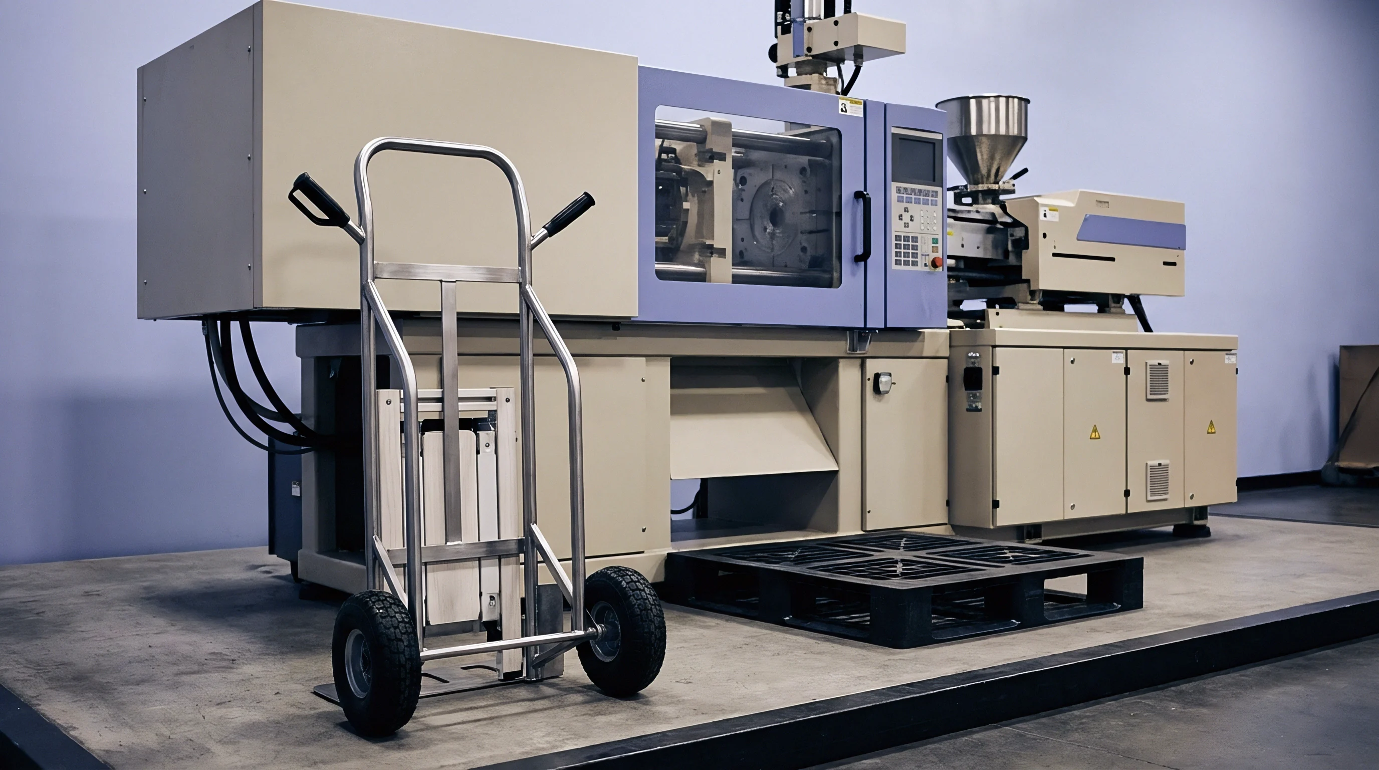
Plumbing

Do Complex Internal Manifolds Compromise Tool Rigidity?
Placing intricate water networks four millimeters beneath a mold cavity removes supportive steel mass that resists cyclical injection forces. High-pressure injection moulding subjects the cavity to clamp tonnages and peak cavity pressures exceeding one thousand bar. If conformal channels run too close to the molding surface or feature sharp internal cross-sectional transitions, stress concentrations trigger fatigue fractures, leaching cooling water into the cavity during the pack phase.
The tooling designer balances fluid path clearance against structural beam deflection under cyclic load.
Manifold designs split between parallel and series configurations dictate both hydraulic stability and thermal uniformity. Toolmakers favor series circuits because all fluid traverses every channel segment, ensuring uniform flow rates without stagnant zones. Series circuits generate massive cumulative pressure drops, requiring immense pump power to sustain turbulence.
Parallel circuits drop overall resistance, allowing lower pump heads, but they invite fluid maldistribution. Coolant takes the path of least resistance through shorter outer passages, leaving central deep-core channels starved and stagnant.
Supply line pressure must exceed the sum of dynamic channel losses and manifold return backpressure to avoid flow stalling in narrow core sweeps.
To balance parallel flow distribution, designers embed calibrated flow restrictors or orifice plates into the lower-resistance branches. Sizing these orifices requires solving the hydraulic loop using the Hardy Cross method or three-dimensional computational fluid dynamics analysis. A balance must be struck across every circuit branch:
- Supply header sizing maintains cross-sectional areas at least two and a half times the combined area of all feeding conformal branches to prevent pressure drops along the distribution rail.
- Elbow bend radius holds a minimum centerline radius of 1.5 times the internal channel diameter to eliminate catastrophic vortex separation and excessive dynamic head loss.
- Bridge distance spacing preserves a minimum pitch-to-diameter ratio of 2.0 between adjacent conformal channels to maintain core rigidity under maximum injection pressure.
- Cavity offset depth enforces a strict steel boundary between three and five millimeters from the plastic show surface, preventing local tool surface thermal hot spots.
Corrosion resistance introduces an additional chemical parameter into the plumbing equation. Additive tool inserts produced from Maraging 300 steel lack the natural chromium content found in conventional 1.2083 or 420 stainless grades. Circulating untreated factory chiller water through raw Maraging steel leads to internal oxidation and pitting within two hundred hours of continuous operation.
Rust flakes break away and clog narrow conformal passages, strangling water delivery. Additive tools require closed-loop demineralized cooling water treated with rust inhibitors, or alternative manufacturing using precipitation-hardening stainless steels like 17-4 PH or Corrax.
Thermal stress cycling compounds the mechanical load inside the plumbing network. As molten resin strikes the cavity surface, the steel shell expands against the colder underlying structure supporting the cooling passages. This thermal gradient generates alternating compressive and tensile stresses across the channel roof.
Finite element analysis must verify that combined von Mises stresses stay well below the endurance limit of the heat-treated additive material to avoid stress corrosion cracking along internal build layers.
Quick-disconnect water couplings on the mould plate frame add another forgotten hydraulic restriction. Threading an eight-millimeter conformal circuit to a standard quick-release socket with an internal valve restriction of five millimeters introduces an immediate localized pressure drop of 0.8 bar at operating velocities. Manifold blocks bolted directly to the insert face eliminate fitting chokes and preserve fluid velocity inside the core.
Suppliers often claim additive tool inserts are drop-in replacements for standard modular tool bases. Press setters discover during hookup that plant plumbing infrastructure cannot supply the pressure margins these tools mandate.


Balance

Transient Mold Surface Temperatures across Multi Cavity Tools
Uniformity across multi-cavity tooling requires identical hydraulic impedance across every insert in the press. Consider an eight-cavity tool producing thin-walled polyoxymethylene medical housings with a nominal wall thickness of 1.2 millimeters. If cavity four exhibits a ten percent higher internal roughness due to uneven powder clearing during manufacturing, its coolant delivery rate drops, its steel runs five degrees hotter, and parts from that cavity emerge undersized due to elevated volumetric shrinkage.
The process window for the whole tool narrows to zero.
| Cavity Index | Flow Rate (L/min) | Reynolds Number | Mold Surface Temp (°C) | Critical Diameter (mm) |
|---|---|---|---|---|
| Cavity 1 | 6.2 | 14,100 | 82.4 | 24.012 |
| Cavity 2 | 6.1 | 13,850 | 82.8 | 24.010 |
| Cavity 3 | 6.3 | 14,300 | 82.1 | 24.015 |
| Cavity 4 (Partially Choked) | 3.8 | 8,600 | 91.3 | 23.948 |
| Cavity 5 | 6.0 | 13,600 | 83.2 | 24.008 |
| Cavity 6 | 6.2 | 14,100 | 82.5 | 24.013 |
| Cavity 7 | 5.9 | 13,400 | 83.6 | 24.004 |
| Cavity 8 | 6.1 | 13,850 | 82.7 | 24.011 |
The operational consequence lands instantly in the inspection lab. Parts from Cavity 4 fail drawing tolerances, but sorting them or blocking off the cavity destroys the batch economics. To bring Cavity 4 into dimensional tolerance, the setter is forced to lengthen holding time and overall cooling time, inflating the cycle from fourteen seconds to nineteen seconds across all eight cavities.
The commercial benefit of conformal cooling disappears under the weight of one hydraulically unbalanced insert.
Digital flow regulators installed at the mold exterior provide cavity-level diagnostic telemetry. Modern installations mount ultrasonic or vortex shedding flow sensors coupled to digital temperature probes on every individual circuit return. When scale builds up or internal channel collapse occurs during production runs, the system flags the anomalous drop in flow rate before parts exceed dimensional boundaries.
Monitoring individual returns replaces manual temperature checking with thermal imaging cameras during mold setup.
Balancing multi-cavity systems demands meticulous hydraulic modeling prior to metal deposition. Engineers treat the coolant distribution tree like an electrical resistor network, sizing runner galleries progressively to ensure equal pressure heads at the entrance of each conformal insert. Computational simulations must model fluid temperature rises along the circuit length; coolant heating past three degrees Celsius from inlet to outlet signals insufficient flow velocity or an over-extended circuit length that compromises cooling efficiency.
Scale deposition presents a relentless operational threat to hydraulic balance. Untreated industrial water carries calcium, magnesium salts, and biological contaminants that form an insulating scale layer inside the passages. In conformal circuits with narrow cross sections, a scale layer merely fifty micrometers thick increases surface roughness, chokes flow, and drops steel thermal conductivity by twenty percent.
Regular chemical flushing using acid descaling flushes restores original hydraulic resistance and maintains cycle speed.
Under typical tool operating conditions, a five-degree shift in mold surface temperature alters semi-crystalline shrinkage enough to move critical dimensions outside DIN 16742 TG4 tolerances.
The setter on shift cannot easily troubleshoot internal thermal balance problems without dedicated instruments. The setter reads barrel temperatures, checks gate freeze times, and inspects the cushion, but cannot see flow starvation occurring deep inside the steel until parts emerge twisted from the mold.

Yield

Cycle Time Reduction Arithmetic and Press Capacity Economics
Evaluating conformal cooling hydraulics is an economic exercise in press capacity expansion. Injection moulding machine hourly rates range from forty-five dollars for an eighty-tonne all-electric machine up to one hundred and eighty dollars for a one-thousand-tonne hydraulic press. Cooling time typically consumes fifty to seventy-five percent of the total cycle for thick-walled technical parts.
Cutting eight seconds out of a thirty-second cycle via turbulent conformal cooling directly slashes the processing cost per unit, unlocking thousands of machine hours across an annual run.
Take an industrial housing moulded in thirty percent glass-filled polyamide 66 with a 3.5-millimeter nominal wall, run on a 300-tonne machine at an operating rate of eighty-five dollars per hour. The component requires an annual production volume of 500,000 units on a four-cavity tool. The baseline gun-drilled tool runs a thirty-four-second cycle time, where cooling time accounts for twenty-two seconds.
The calculated machine commitment totals 1,180 hours of production time, translating to an annual machine processing cost of $100,300.
A properly engineered conformal cooling package drops cooling time from twenty-two seconds down to twelve seconds by pulling heat uniformly from internal blind cores. The total cycle drops from thirty-four seconds down to twenty-four seconds. Operating assumptions and financial metrics illustrate the resulting commercial return:
- Total machine hours required fall from 1,180 hours to 833 hours per year, liberating 347 machine hours of capacity on the 300-tonne cell for alternative revenue-generating work.
- Annual press processing expense drops from $100,300 down to $70,805, delivering direct operating savings of $29,495 on machine time alone.
- Additive insert premium adds $14,000 in upfront tooling costs for four DMLS inserts including abrasive flow machining post-processing, yielding full capital payback in under six months of steady production.
- Part reject rates from warpage decline from 4.2 percent to 0.8 percent due to balanced heat extraction across nominal wall transitions, saving $8,500 in scrap resin.
If hydraulic planning is neglected and the cooling passages choke, that return profile reverses entirely. An undersized cooling channel forces the setter to prolong the hold and cool phases to manage localized hot spots, freezing the cycle at thirty-two seconds. The moulder absorbs the $14,000 additive manufacturing tooling surcharge without extracting the cycle time savings, destroying the investment thesis.
The buyer receives invoices carrying high tool amortization costs with zero piece-price reduction.
Tool supply contracts must state cooling performance requirements explicitly. Agreements should stipulate that mold sign-off requires demonstrating specific flow rates, circuit pressure drops, and thermal surface uniformity under production conditions. Omitting hydraulic acceptance criteria from tooling procurement documentation leaves the buyer paying for advanced additive tooling that fails to achieve projected cycle times on the production floor.
The contract clause specifying hydraulic performance shifts financial liability for unachieved cycle times directly back to the toolmaker.