Shutoff Face Mechanical Compression Mechanics in High Cavitation Injection Molds
Parting line shutoffs require primary seal land stress below steel yield limits and preloaded support pillars to prevent platen deflection flash.
Contact
Preload calculations on parting line land areas dictate whether a high-cavitation injection mould seals cleanly or flashes under peak injection pressure. In tools running 32 to 128 cavities, shutoff faces serve a dual mechanical role. They act as the physical stop that arrests clamping force across the parting line, and they provide the zero-clearance barrier preventing liquid polymer melt from escaping the impression.
Direct mechanical compression on these narrow landing zones routinely exceeds the yield strength of standard tool steels if platen force distribution, land area geometry, and thermal expansion are improperly balanced.
Elastic Deformation and Stress Distribution at the Parting Line
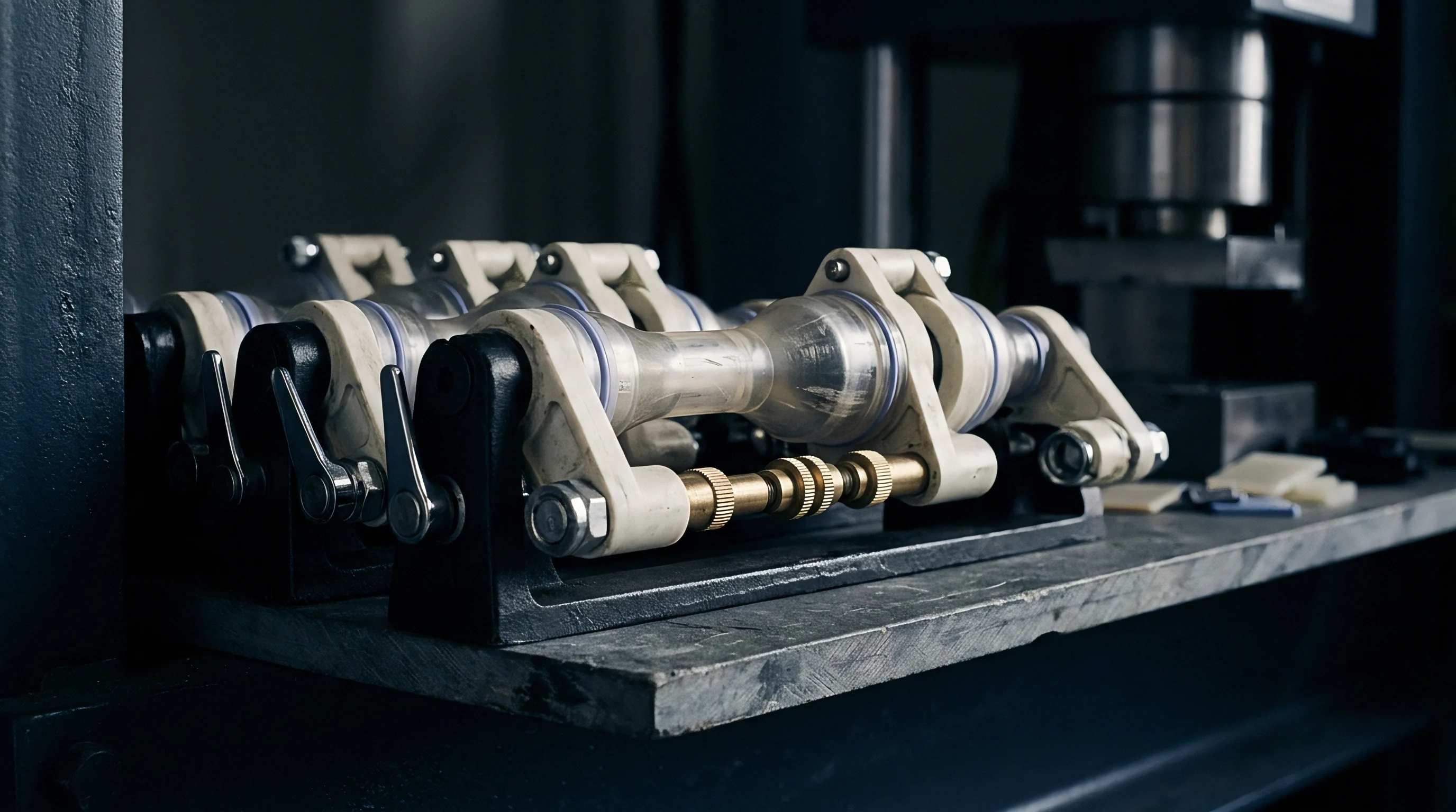
The parting line shutoff does not operate as a rigid, unyielding barrier. High-cavitation moulds experience elastic strain across every contact face when the hydraulic or toggle clamp locks the tool. Calculate nominal contact stress by dividing the net clamping force by the projected contact area of all shutoff lands.
A 300-tonne press delivering 2,943 kN across a tool with 1,200 square millimetres of primary shutoff area generates a nominal static compressive stress of 2,452 MPa. This figure exceeds the compressive yield strength of hardened 1.2343 tool steel at 52 HRC, which sits near 1,650 MPa.
To avoid plastic deformation and hobbing, land area design balances parting line compression through primary seal lands and secondary dump lands. Primary shutoff lands surround the cavity perimeter with a land width ranging between 1.2 mm and 2.5 mm. Secondary compression lands sit outside the runner system, standing 0.015 mm to 0.025 mm lower than the primary shutoff.
These secondary zones take up excess platen load once the primary land undergoes acceptable elastic compression of 0.008 mm to 0.012 mm.
Parting line preload exceeding 1,200 MPa on primary shutoff lands causes permanent hobbing within fifty thousand cycles.
When compressive stress forces shutoff faces into the plastic deformation regime, steel coining occurs. Coining reduces the effective land height, closing vent channels and opening micro-gaps at cavity edges. This mechanical breakdown shifts the process window, requiring higher clamp forces to contain flash, which accelerates tool fatigue.
| Tool Steel Grade | Hardness (HRC) | Yield Strength (MPa) | Primary Land Width (mm) | Elastic Strain at Peak Load (%) | Hobbing Risk Threshold |
|---|---|---|---|---|---|
| 1.2343 / H13 ESR | 52 ~ 54 | 1,650 | 1.8 | 0.12 | Moderate above 1,400 MPa |
| 1.2083 / 420 SS | 50 ~ 52 | 1,480 | 2.2 | 0.15 | High above 1,250 MPa |
| 1.2767 / 45NiCrMo16 | 54 ~ 56 | 1,820 | 1.5 | 0.10 | Low below 1,600 MPa |
| Beryllium Copper C17200 | 38 ~ 40 | 980 | 3.0 | 0.22 | Critical above 800 MPa |
Melt pressure inside the cavity acts directly against the clamp force. Peak injection pressures reaching 150 to 220 MPa generate internal hydraulic forces that push cavity halves apart. In a 64-cavity medical dropper tool with a combined projected cavity area of 18,000 square millimetres, an internal melt pressure of 120 MPa exerts 2,160 kN of parting force.
Clamp force must exceed this internal force by a safety factor between 1.2 and 1.4 to maintain shutoff integrity without crushing shutoff lands during dry cycling.
Excessive land reduction causes rapid shutoff failure. Molders grinding land areas to clear flashing often concentrate clamping force onto smaller surface areas. This action doubles contact stress, crushing the steel faster during subsequent production runs.


Deflection
High-cavitation press platens bend under tonnage. Center-push hydraulic cylinders and toggle linkage points apply localized forces that flex master plates, support pillars, and mold bases. Platen bowing creates non-uniform contact pressure across shutoff faces, compressing outer cavities while center cavities experience parting line separation under peak hydraulic pressure.
Platen Deformation Profiles and Cavitation Core Spacing
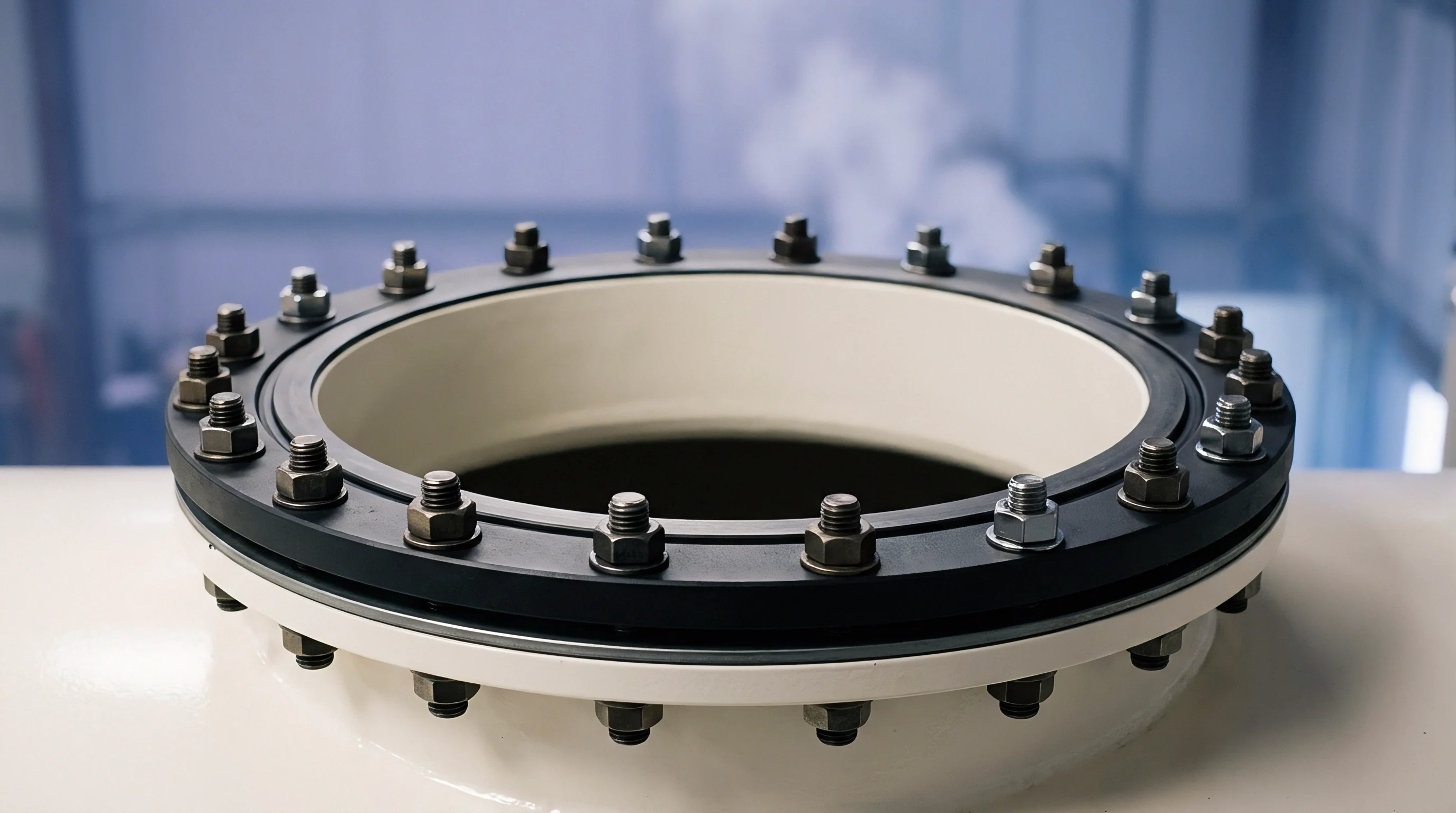
Platen deflection manifests as a parabolic curve across the mold face. In a 64-cavity mold mounted on a 4,000 kN press, central platen deflection reaches 0.035 mm to 0.060 mm under full locking force. Cavities located at the geometric center of the mold layout experience reduced shutoff compression prior to injection.
When melt enters central cavities, hydraulic pressure opens the shutoff gap, generating parting line flash. Outer cavities experience localized over-compression, leading to steel fatigue and micro-cracking.
Engineers calculate plate thickness and support pillar spacing to counteract bending moments. Standard support pillar arrangements must restrict mold plate deflection to less than 0.010 mm across the entire cavity array. Bending deflection w for a uniform mold plate under central load follows structural beam equations:
w = fracC · F · L3E · I
Where F represents total clamping load, L equals span between support pillars, E defines Young’s modulus of the mold plate steel, I is the area moment of inertia, and C is the support boundary coefficient.
- Platen parallelism verification measures dynamic deflection across four corners using dial indicators under full tonnage.
- Support pillar preload setting requires pillars to ground 0.030 mm to 0.050 mm taller than surrounding ejector space gaps to account for axial compression.
- Parting line crown grinding adds 0.015 mm to 0.025 mm of material height to central mold regions to compensate for calculated platen flex.
- Cavity pressure balancing adjusts individual gate diameters across inner and outer rings to equalize internal hydraulic parting forces.
Thermal gradients aggravate mechanical plate bending. A core side operating at 80 degrees Celsius expands more than a cavity side running at 30 degrees Celsius. In a 1,000 mm long mold base, a 50 degree thermal differential produces 0.60 mm of differential thermal expansion.
This expansion shifts shutting surfaces relative to each other, causing scuffing and galling along vertical bypass shutoffs.
Differential thermal expansion breaks vertical shutoff land engagements. Outer cavities slide past matching steel walls at improper alignment angles, shearing metal particles into the cavity impressions.
A temperature difference of fifteen degrees Celsius across a thousand millimeter mold base shifts cavity shutoff centers by zero point zero90 millimeters.
Tooling engineers mitigate thermal growth mismatches by placing core alignment locks at the mold centerline. Zero-clearance side locks absorb thermal expansion symmetrically outward from the center axis, keeping shutoff faces parallel throughout heat-up and stabilization cycles. Neglecting thermal expansion dynamics when setting shutoff land preloads results in permanent parting line damage on cold tool start-ups.

Hardness
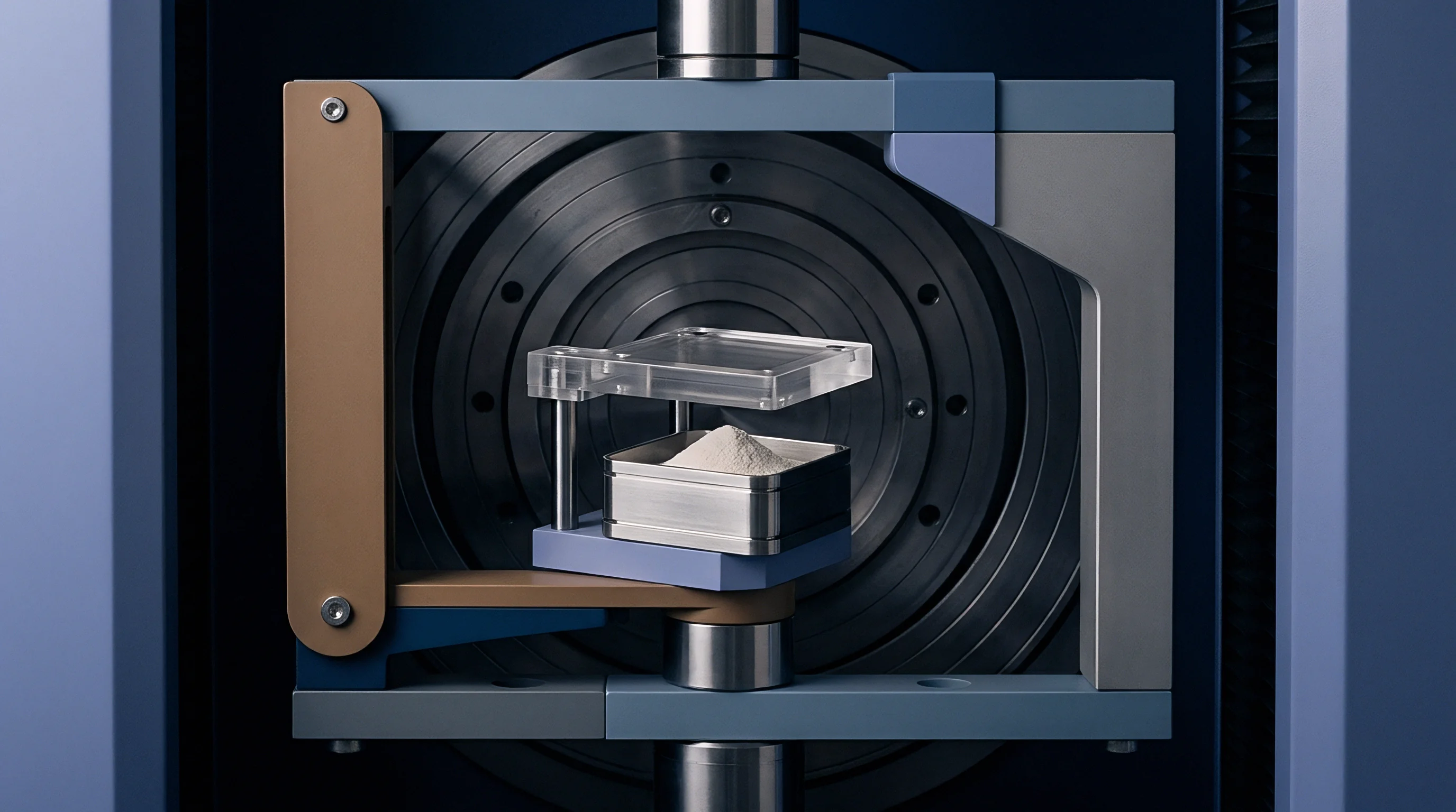
Steel selection and surface treatment specify how shutoff faces withstand repetitive mechanical impact and high-velocity abrasive resin flow. High-cavitation tools running polyolefins, glass-filled resins, or fluoropolymers face distinct wear modes along their parting seals. Mechanical compression demands high yield strength, while venting zones require resistance to micro-abrasion and chemical gas erosion.

Substrate Metallurgy and Advanced Surface Coatings
Through-hardened tool steels supply the structural backbone for shutoff durability. Premium powder-metallurgy steels like CPM 1V, Vanadis 4 Extra, and Elmax yield uniform carbide distribution, eliminating soft ferrite pockets that lead to localized shutoff collapse. For stainless steel requirements, ISO 1.2083 and 1.2316 offer corrosion protection against acidic off-gassing, though their compressive strength stays below through-hardened hot-work steels like ISO 1.2343 at peak hardness.
| Material / Coating | Hardness (HV / HRC) | Compressive Strength (MPa) | Coeff. of Friction | Primary Failure Mechanism |
|---|---|---|---|---|
| ISO 1.2343 (H13 ESR) | 54 HRC | 1,650 | 0.65 | Hobbing under over-tonnage |
| ISO 1.2083 (420 SS) | 52 HRC | 1,480 | 0.70 | Edge rolling and pitting |
| CPM 4V Tool Steel | 60 HRC | 2,100 | 0.55 | Micro-chipping under impact |
| Physical Vapor Deposition TiAlN | 3,000 HV | N/A (Thin Film) | 0.30 | Coating delamination from substrate flex |
| Diamond-Like Carbon (DLC) | 2,200 HV | N/A (Thin Film) | 0.15 | Substrate yielding under localized load |
Surface coatings augment substrate performance. Physical Vapor Deposition (PVD) applies thin, highly dense films of Titanium Aluminum Nitride (TiAlN) or Chromium Nitride (CrN) at thicknesses between 2 and 4 micrometers. These coatings deliver surface hardness levels exceeding 2,500 HV, preventing galling on sliding angled shutoffs.
Thin coatings cannot support high compressive loads if the underlying steel deforms. Thin film coatings flex with the substrate; if the core steel yields at 1,500 MPa, the 3,000 HV coating cracks like eggshell over soft substrate.
Nitriding creates a diffusion layer that elevates surface hardness to 65 ~ 68 HRC while maintaining a tough core structure. Liquid or gas nitriding increases wear resistance on venting shutoff lands. Salt bath nitriding must be controlled to prevent brittle white-layer formation.
A white layer thicker than 0.003 mm chips away during parting line impact, releasing abrasive particles into sliding mold components.
Toolmakers often claim that adding a hard coating solves parting line flash. Flash indicates plate deflection or crushed land area, which no thin surface film can correct.
Vector
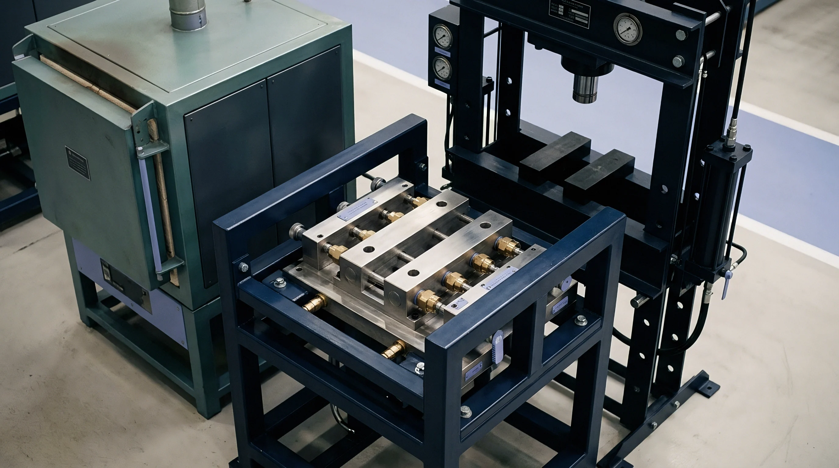
Angled shutoffs, core bypass seals, and sliding core interfaces convert vertical clamping forces into lateral compressive loads. High-cavitation molds producing complex geometry, such as syringe barrels, thread closures, and electrical housings, rely on angled shutoff vectors to form holes, undercuts, and side latching features. Mechanical wear and clearance management on angled vectors determine shutoff longevity.

Kinematic Loading on Bypass Shutoffs and Core Interlocks
Vertical shutoffs close perpendicular to parting line travel, taking direct axial compression. Angled bypass shutoffs slide past matching steel faces at an angle thη relative to the mold opening axis. As angled shutoffs engage, normal contact force Fn scales with the angle of draft:
Fn = fracFaξalsin(thη) + μ · cos(thη)
Where Faξal represents the locking force transmitted along the press stroke direction, and μ is the coefficient of static friction between sliding steel faces. Draft angles below 3 degrees increase friction and galling risks, while angles above 10 degrees require significant lateral steel mass to resist deflection.
- Interlocking angle geometry requires a minimum of 5 degrees draft on side-action shutoffs to avoid severe scuffing during core entry.
- Heel block preload calculations dictate a 0.020 mm to 0.040 mm interference fit against slide bases to absorb side thrust forces generated by melt injection.
- Guided ejector alignment uses hardened leader pins and graphite-bronze bushings to restrict core shift to under 0.005 mm prior to shutoff contact.
- Wear plate sacrificial clearance sets slide wear plates 2 HRC softer than shutoff steel, allowing controlled wear on easily replaceable components.
A 7-degree bypass shutoff on a 128-cavity pipettor mold experiences severe lateral thrust forces during mold closure. If side core slides flex outward by 0.012 mm under injection pressure, melt creeps into the parting line gap, creating circumferential flash. Heel blocks mounted behind sliding cores must back up the slide steel, transmitting lateral vector forces directly into the solid mold frame.
Sliding cores without backing blocks deflect under cavity pressure. The resulting gap allows plastic to enter sliding mechanisms, seizing core action within a single cycle.
The standard supply contract specifies that mold inserts must hold nominal part dimensions for one million cycles without manual fitting or shimming. Toolmakers must design vector shutoffs with replaceable hardened insert pads to meet this standard without rebuilding entire core blocks.

Margin
Financial viability in high-cavitation injection molding depends on cycle time efficiency and complete tool reliability across millions of shots. Unplanned tool maintenance driven by crushed shutoff faces, parting line flash, or galled sliding cores directly destroys piece-price margins. Tooling amortisation calculations must factor in mandatory shutoff refurbishments alongside raw material and machine shop hourly rates.
Amortisation Mechanics and Total Landed Part Costs
A 64-cavity tool costing 350,000 USD running a 4.5-second cycle generates 51,200 parts per hour at 100 percent yield. At an operating rate of 85 USD per hour on a 250-tonne electric press, machine shop processing costs equal 0.00166 USD per part. Amortising the tooling investment over 20 million parts adds 0.01750 USD per part.
If parting line shutoffs fail at 2 million cycles due to excessive compression land stress, tool refurbishments cost 35,000 USD per event, requiring 48 hours of downtime.
Consider the total landed cost impact of premature shutoff wear across a 50-million-part production run under two different tool construction strategies.
Assume Strategy A utilizes standard 1.2343 tool steel with simple flat shutoffs and un-preloaded support pillars. Strategy B incorporates CPM 4V inserts, guided zero-clearance side locks, preloaded support pillars, and secondary relief lands.
Strategy A experiences shutoff hobbing and flash every 2.5 million shots, incurring ten repair events totaling 250,000 USD and 480 hours of lost machine output. Lost production capacity represents 24,576,000 unproduced parts, creating stock-out penalties and idle press overheads. Strategy B adds 65,000 USD to initial tooling cost but extends shutoff maintenance intervals to 10 million cycles, requiring only four minor clean-up events totaling 40,000 USD and 96 hours of downtime.
The landed cost differential demonstrates that upfront steel discipline and mechanical compression modeling yield substantial financial savings per delivered unit over the program life.
| Cost Component | Strategy A (Standard Construction) | Strategy B (Engineered Shutoffs) | Cost Variance |
|---|---|---|---|
| Initial Tooling Capital Expenditure | $320,000 | $385,000 | +$65,000 |
| Maintenance & Shutoff Repairs | $250,000 | $40,000 | -$210,000 |
| Downtime Press Overhead ($85/hr) | $40,800 | $8,160 | -$32,640 |
| Scrap Loss from Flash (0.8% vs 0.1%) | $48,000 | $6,000 | -$42,000 |
| Amortised Tool Cost per Part | $0.01317 | $0.00878 | -$0.00439 |
Piece-price calculations must account for progressive shutoff wear. As shutoff lands experience wear, molders increase clamping tonnage to prevent flashing. Increasing clamp tonnage accelerates platen deflection and tool fatigue, leading to sudden, catastrophic tool failure.
Proper maintenance schedules enforce shutoff inspections every 500,000 cycles, evaluating land height using optical profilometry and replacing worn wear plates before parting line steel sustains permanent deformation.
Tracking peak cavity pressure trends alongside clamp tonnage settings provides early warnings of shutoff degradation. When press setters increase clamp force by more than ten percent above initial baseline validation levels to stop flash, shutoff lands have passed their elastic deformation limit.