Unresolved Weld Line Degradation Kinetics under Biaxial Thermal Mechanical Fatigue in Mapped Fiber Composites
Weld line biaxial fatigue resistance requires sequential valve gating or variotherm tooling to eliminate severe matrix-dominated knockdown under cyclic thermal strain.


Flaw
Injection moulded short-glass and short-carbon thermoplastics drop between 35 and 65 percent of their nominal room-temperature tensile strength when two opposing melt fronts meet. The resulting weld line represents an abrupt spatial discontinuity in the second-order fiber orientation tensor. Under cyclic biaxial thermal mechanical fatigue, this planar weakness accumulates damage along rates that current commercial structural simulation packages fail to predict.
Linear Miner sums and uniaxial fatigue master curves consistently overstate component operating lifespans by four-fold to ten-fold under combined pressure and fluctuating operating temperatures.
The standard multi-scale simulation workflow maps fiber orientation tensors from an injection simulation mesh directly to a structural finite element grid. State-of-the-art orthotropic mapping techniques transfer flow-induced fiber alignment with spatial interpolation errors under five percent across bulk wall geometries. These tools fail directly at the contact plane.
Moldex3D and Autodesk Moldflow assign weld line nodes based on intersecting flow fronts where the meeting angle sits below a programmer-defined threshold, typically 135 degrees. The mapped mechanical model then applies an arbitrary knockdown factor, commonly selected between 0.4 and 0.7, to the isotropic matrix properties or to the composite stiffness tensor across a single element layer.
A nominal weld knockdown factor of 0.5 applied uniformly across a finite element boundary creates a false sense of structural margin under fluctuating multi-axis thermal strain fields.
Commercial finite element formulations evaluate biaxial fatigue by coupling local anisotropic stress states to stress-life or strain-life curves obtained from unidirectional dogbone specimens. Tensile specimens harvested according to ISO 20753 Type 1A with double-gated cavities force fibers to lay purely perpendicular to the applied tensile vector. In an operating structural component, such as a high-pressure cooling circuit header or an automotive integrated thermal management module, the local stress field rarely remains uniaxial.
Instead, the wall experiences simultaneous out-of-phase normal stresses, cyclic through-thickness shear from pulsating internal fluids, and thermal gradients that generate differential cyclic thermal expansion.
The microstructural morphology of a mapped weld line consists of a resin-rich core, virtually devoid of reinforcing fibers, flanked by narrow regions of planar fiber alignment oriented entirely parallel to the interface. Fibers do not bridge the meeting plane. Resistance to fatigue crack initiation depends solely on polymer chain autohesion, intermolecular entanglement across the boundary, and the cyclic endurance of the unreinforced matrix.
When the surrounding anisotropic composite expands and contracts under rapid temperature cycling, severe micro-mechanical constraint occurs. The stiff bulk composite restricts the free thermal strain of the unreinforced weld zone. Cyclic triaxial stresses develop precisely where the polymer possesses its lowest ultimate elongation.
Process engineers frequently attempt to mitigate this interfacial deficit by manipulating packing pressure and melt temperature. Increasing melt temperature raises polymer chain mobility and promotes interdiffusion across the contact boundary, yet it also accelerates thermal oxidation kinetics if residence times extend past four minutes. Elevating packing pressure up to 1200 bar packs additional volumetric melt into the interface, reducing micro-void formation.
Neither process modification alters the fundamental spatial physics of the fibers: rigid short glass rods cannot turn across an impingement plane to establish physical re-entanglement.


Flux
Cyclic thermal mechanical fatigue accelerates microstructural degradation through two coupled phenomena: mechanical matrix micro-cracking and progressive chemical-physical embrittlement. Standard testing protocols decouple these phenomena by executing mechanical fatigue under strictly isothermal conditions, subsequently evaluating oxidation through unstressed thermal aging chambers. In operational hardware, mechanical strain and thermal flux act simultaneously, producing synergistic degradation kinetics that outpace linear superposition models.
Polyamides (PA66, PA6) and polyphthalamides (PPA) reinforced with 30 to 50 percent short glass fibers dominate under-hood and structural fluid-handling systems. These semi-crystalline matrices undergo post-crystallization, continuous physical aging, and thermo-oxidative chain scission when exposed to cyclic operating temperatures swinging between negative 40 and 150 degrees Celsius. In the resin-rich weld line interface, the absence of fiber heat dissipation creates localized thermal hot spots.
Atmospheric oxygen and glycol-water heat transfer fluids diffuse into the unreinforced matrix zone along accelerated rates. The polymer matrix suffers reduction in weight-average molecular weight, dropping chain length and destroying the entanglement network required for cyclic plastic deformation.
| Exposure Condition | Tensile Modulus (GPa) | Ultimate Tensile Stress (MPa) | Molecular Weight Retention (%) | Fatigue Life at 45 MPa (Cycles) |
|---|---|---|---|---|
| Virgin Molded State | 10.8 ± 0.4 | 175 ± 5 | 100.0 | 120000 |
| Isothermal Fatigue (23°C) | 10.2 ± 0.3 | 158 ± 6 | 98.5 | 68000 |
| Isothermal Fatigue (130°C) | 6.4 ± 0.2 | 84 ± 4 | 91.2 | 14500 |
| Unstressed Thermal Aging (130°C) | 9.9 ± 0.5 | 115 ± 7 | 76.4 | 31000 |
| Coupled Biaxial Fatigue (TMF) | 5.8 ± 0.3 | 52 ± 5 | 61.8 | 2300 |
The interaction between non-isothermal loading and dynamic mechanical dissipation causes rapid cyclic softening. Under high-frequency cyclic loading, polymers dissipate energy via mechanical hysteresis, generating internal heat. At the weld line, the loss modulus is governed entirely by the neat polymer matrix.
Because the adjacent bulk material exhibits substantially higher thermal conductivity along the aligned fibers, an extreme thermal gradient forms across a zone less than 200 micrometers wide. The local temperature in the weld line easily exceeds the glass transition temperature of conditioned PA66, triggering premature micro-void coalescence along the interface.
Constitutive Modeling of Interfacial Viscoplasticity
Analytical life prediction models require constitutive laws that account for asymmetric tension-compression behavior and evolving viscoplasticity. Standard structural fatigue solvers rely on isotropic Ramberg-Osgood formulations modified by Tsai-Hill or Tsai-Wu failure criteria. These models treat the weld line as an isotropic strip embedded between two anisotropic domains.
They ignore the coupled ratcheting and mean stress relaxation occurring under non-symmetric biaxial loading cycles.
A physically rigorous formulation demands an anisotropic Chaboche kinematic hardening framework linked to an internal state variable representing chemical degradation. Matrix damage accumulation rate can be expressed through a modified continuum damage mechanic equation:
dD/dN = ^s exp( -E_act / (R_gas T_peak) )
Here, D represents the scalar damage variable where failure occurs at unity; sigma_eq is the equivalent biaxial stress amplitude; S and s are temperature-dependent material parameters; E_act is the apparent activation energy for thermal oxidative degradation; R_gas is the universal gas constant; T_peak is the maximum cycle temperature in Kelvin; sigma_hydro is the hydrostatic stress component; and beta is a multiaxial coupling parameter scaling the effect of hydrostatic tension on void enlargement. When hydrostatic tension increases, void growth accelerates exponentially, explaining why pressurized components fail at weld lines under cyclic internal pressure far below their uniaxial fatigue limits.
Hydrostatic tensile stress components multiply the effective damage accumulation rate at unreinforced weld boundaries during thermal cycling.
Unresolved disputes persist regarding the temperature-frequency equivalence at the weld line interface. Time-temperature superposition principles hold reliably for linear viscoelastic responses in homogenous polymers. For mapped fiber composites undergoing combined thermal degradation and large-strain viscoplastic damage, frequency acceleration factors break down.
Running accelerated physical bench tests at 5 Hz instead of an operational 0.05 Hz suppresses thermal-oxidative transport mechanisms while artificially overdriving hysteretic self-heating. Laboratory acceleration tests consistently mischaracterize the primary failure mode, reporting thermal runaway melting where field hardware experiences brittle fatigue cracking.
Determining whether fatigue damage or chemical embrittlement initiates the primary micro-crack remains an active industry debate. One group of structural analysts argues that cyclic micro-strains mechanically fracture matrix tie molecules across the interface, opening micro-cracks that subsequently admit environmental oxidizers. Another faction maintains that oxygen diffusion and selective thermal oxidation embrittle the unbonded skin layers first, initiating brittle surface cracks that rapidly propagate through the thickness under cyclic fatigue.
Process engineers who must warranty five-year production runs cannot wait for academic consensus on this sequence.
Rupture
Failure along a mapped weld boundary operates via a progressive, multi-stage mechanism governed by local boundary conditions. Crack initiation begins at the outer surfaces of the part where the converging melt fronts form an exterior V-notch. Toolmakers designate this defect as the weld line score mark.
The notch depth varies between 1 and 15 micrometers depending on cavity venting efficiency, packing pressure, and mold surface temperature. This geometric feature acts as an immediate micro-crack starter, driving a local stress concentration factor between 2.2 and 3.8 under biaxial bending loads.
Once a micro-crack initiates within the V-notch root, it enters the skin-shear zone. In this layer, shear flows induce a localized alignment of fibers parallel to the external wall surface but strictly coplanar with the weld interface. The crack encounters zero transverse fibers to trigger crack deflection or fiber pull-out dissipation mechanisms.
Growth through this region proceeds along mode I opening conditions under biaxial hoop stress, progressing rapidly through the first 100 to 200 micrometers of wall thickness.
Why Does Triaxial Stress Accelerate Core Delamination?
Deeper in the core of the moulding, the mechanical state shifts from plane stress to severe plane strain. Short fibers in the core typically retain an orientation distribution dictated by the fountain flow pattern, laying perpendicular to the principal fill direction but parallel to the impingement boundary. The complete lack of reinforcing fibers across the weld plane means the bulk composite cannot transfer load via shear stress transfer along the fiber-matrix interface.
Instead, normal stresses pull the resin apart directly at the weld seam.
Under cyclic biaxial thermal mechanical loading, differences in Poisson ratios between the bulk composite and the unreinforced weld zone generate through-thickness shear stresses. The bulk material exhibits an anisotropic Poisson ratio ranging from 0.32 to 0.44 depending on orientation relative to flow, whereas the neat weld line matrix demonstrates a classic viscoelastic value approaching 0.48 near peak temperatures. This mechanical mismatch generates intense localized shear stresses along the narrow boundaries flanking the weld core, causing interfacial micro-debonding between the first row of oriented fibers and the neat matrix core.
The final rupture event occurs catastrophically. As cyclic micro-cracks advance from both outer surfaces inward toward the core, the remaining load-bearing ligament undergoes rapid strain localization. Under high-temperature excursions, this remaining cross-section yields via ductile tearing, leaving visible plastic whitening.
Under low-temperature cycle excursions (negative 40 degrees Celsius), the same ligament shatters via brittle cleavage. An engineer inspecting a failed pressure vessel will frequently find both morphologies on the same fracture surface, demonstrating that cycle temperature at the precise instant of final crack instability dictates the macroscopic failure appearance.

Rig
Evaluating weld line durability under combined thermal and biaxial mechanical fields requires specialized physical test benches capable of synchronous temperature and load control. Standard uniaxial servo-hydraulic load frames cannot replicate the triaxial stress states observed in structural pressure housings or restrained structural brackets. Validated fatigue protocols utilize cruciform specimens or internally pressurized tubular test geometries containing precisely positioned, opposed-gate weld seams.
Internally pressurized hollow specimens produced via balanced two-gate cold runner tooling represent the most accurate representation of field stress states. These specimens allow independent control of hoop stress via cyclic internal oil or glycol pressurization (up to 150 bar at frequencies up to 2 Hz) and axial stress via coupled linear actuators. Synchronized environmental chambers drive ambient temperatures across the required profile, typically cycling from negative 40 to 140 degrees Celsius with controlled dwell periods to promote thermal equilibrium throughout the wall thickness.
Design and execution of rigorous qualification testing requires strict adherence to physical control requirements across four discrete phases:
- Pre-Conditioning Phase stabilizes specimen moisture content according to ISO 1110 to achieve equilibrium at 50 percent relative humidity and 23 degrees Celsius, eliminating uncontrolled dry-as-molded plasticization shifts during subsequent cyclic testing.
- Thermal Baseline Sweep uses dynamic mechanical analysis (DMA) across a frequency range of 0.1 to 10 Hz to identify shifting storage and loss moduli, defining maximum allowable mechanical cyclic test frequencies that prevent hysteretic self-heating from exceeding 3 degrees Celsius above ambient chamber setpoints.
- Biaxial Cyclic Loading applies synchronized in-phase or out-of-phase axial and hoop load waveforms at target biaxial stress ratios (typically lambda equals 0.5 for pure pressure vessel hoop loading, or lambda equals 1.0 for equibiaxial tension), continuously logging specimen surface strain via non-contact 3D digital image correlation.
- Microstructural End-Point Audit sections the fractured weld interface to evaluate crack path paths, measuring residual resin molecular weight via gel permeation chromatography and documenting local fiber orientation distributions using high-resolution micro-computed tomography.
Cruciform testing presents complex boundary challenges. Stress concentrations naturally migrate toward specimen corner radii rather than the central evaluation zone. To force failure directly into the mapped weld line, cruciform test geometries require a central reduced-thickness pocket.
Machining this pocket into a molded plaque severs continuous skin layers and alters the internal stress profile. Specimen geometries must therefore be molded to finished net shape using dedicated tooling inserts containing opposed gates, maintaining natural mold-cooled skin-core morphologic structures across the entire gauge zone.
Digital image correlation (DIC) remains an indispensable diagnostic tool during multiaxial bench testing. High-speed optical stereoscopic systems track microscopic surface strain fields across the weld seam throughout environmental cycling. A typical 35 percent short-glass PA66 composite displays bulk elastic strain fields between 0.3 and 0.6 percent under working fatigue loads.
The DIC strain map reveals local strain concentrations spanning 1.8 to 2.4 percent directly over a 500-micrometer band encompassing the weld line. This localized plastic strain ratcheting serves as an absolute precursor to macro-crack initiation, detectable thousands of cycles before physical separation occurs.

Tooling
Tooling geometry and thermal circuit design govern the structural integrity of every weld line produced. When a product designer places features requiring cores, side actions, or multiple gates, weld lines become geometrically inevitable. The mold designer owns the initial physical defense against early fatigue degradation.
Steel design decisions dictate melt front convergence angles, cavity venting efficiency, and local wall freeze times, which together establish the baseline strength of the interface before the part ever experiences a thermal cycle.
Controlling the melt front convergence angle is the single most critical geometric lever. When two flow fronts meet head-on at an angle approaching 180 degrees, a true impinging weld line forms, yielding the lowest mechanical strength. If the tooling redirects melt fronts to join at an acute angle below 45 degrees, the flow changes to a meld or knitting line.
The downstream flow vectors induce longitudinal shear, orienting a significant fraction of fibers parallel to the bulk flow and across the meeting interface. Toolmakers achieve this by optimizing gate locations, modifying cavity runner lengths, or introducing intentional wall thickness variations that accelerate flow fronts around one side of an obstruction.
| Design Strategy | Tooling Cost Delta (%) | Cycle Time Impact (s) | Fatigue Life Extension Factor | Dimensional Risk Grade |
|---|---|---|---|---|
| Standard Opposed Gating (Baseline) | 0.0 | 0.0 | 1.0 (Baseline) | DIN 16742 TG4 |
| Sequential Valve Gating (SVG) | +18 to +25 | -1.5 to -3.0 | 3.5 to 5.2 | DIN 16742 TG3 |
| Conformal Fast-Cycling Variotherm | +22 to +35 | +4.0 to +8.0 | 2.8 to 4.1 | DIN 16742 TG4 |
| Overflow Well (Dump Cavity) Design | +4 to +7 | +1.0 to +2.0 | 1.8 to 2.4 | DIN 16742 TG5 |
| Local Wall Flow Profiling (Racetrack) | +2 to +5 | 0.0 | 1.4 to 1.9 | DIN 16742 TG4 |
Sequential valve gating (SVG) eliminates structural weld lines entirely by controlling hot runner valve pin timing. In a two-gate housing, Gate B remains closed as Gate A fills the initial cavity volume. The melt front passes Gate B completely before its pin retracts.
The second melt stream enters behind the primary flow front, eliminating the impingement interface. SVG hot runner manifolds require hydraulic or servo-electric pin actuation, dedicated valve gate sequence controllers, and precise runner balancing. This hardware adds 15,000 to 45,000 USD to tooling capital expenditure, yet it removes the single greatest cause of structural field failure in pressurized composite housings.
Eliminating an impingement weld line via sequential valve gating removes the multiaxial knockdown penalty without lengthening the injection cooling phase.
When gating cannot eliminate an impingement line, mold designers integrate sacrificial overflow wells. Positioned directly opposite the convergence point outside the nominal part boundary, these wells pull the initial meeting fronts out of the structural component wall. The cooler, oxidized leading edges of the melt fronts discharge into the overflow pocket, allowing hotter, well-mixed melt to fill the final part boundary.
The overflow pocket is excised via secondary degating or automated robotic trim stations during part ejection. While this method adds nominal plastic runner scrap and trimming tooling costs, it consistently raises dynamic weld line retention values by 40 to 60 percent.
Variotherm mold heating systems apply rapid localized thermal cycling to weld zones. Using high-pressure water circuits or localized ceramic induction heaters embedded within tool inserts, the steel temperature at the predicted weld zone is driven above the resin melting temperature (260 degrees Celsius for PA66) immediately prior to cavity filling. The melt fronts meet without freezing a solidified skin layer.
Molecular chains interdiffuse across the liquid boundary, and fiber freeze-off is delayed, permitting moderate transverse orientation under high holding pressures. The tool then rapidly chills the insert before mold opening. This thermal cycling extends the moulding cycle time by four to eight seconds, imposing a measurable piece-price penalty that buyers must balance against fatigue life gains.
Venting design requires strict execution at the weld intersection. Entrapped air and volatile degradation gases compressed by the meeting fronts create local micro-dieseling, burning the resin and forming microscopic voids along the boundary. Toolmakers must install active venting paths across the parting line, precisely sizing vent depths between 0.015 and 0.025 millimeters for semi-crystalline polyamides.
Vent depths exceeding 0.030 millimeters permit flash formation, whereas vent depths below 0.010 millimeters cause localized gas trapping. Vacuum-assisted evacuation circuits built directly into the mold core offer complete air evacuation prior to shot injection, eliminating micro-void formation and preserving interface autohesion integrity.


Margin
Translating laboratory fatigue kinetics and tooling mitigations into procurement specifications requires a clear commercial and risk calculation. Sourcing managers frequently contract components based on initial tooling quotations, discovering late in production that fatigue-induced weld failures demand radical tool changes or part re-designs. Preventing this scenario requires embedding fatigue knockdown criteria, verification testing standards, and cavitation economics directly into early development budgets.
Achieving required dimensional tolerances under DIN 16742 complicates weld line placement. Fibers orienting parallel to a weld interface cause anisotropic shrinkage gradients. Polyamides reinforced with 35 percent short glass shrink approximately 0.2 to 0.4 percent along the fiber direction, yet transverse shrinkage ranges from 0.7 to 1.1 percent.
Where a weld line forms, the abrupt shift in fiber alignment induces localized differential shrinkage, manifesting as sink marks, localized wall thinning, or twisting warpage. Toolmakers forced to hold DIN 16742 Tolerance Grade 3 (TG3) often shift gate locations to control part flatness, unintentionally driving the weld line into regions of high cyclic operational stress.
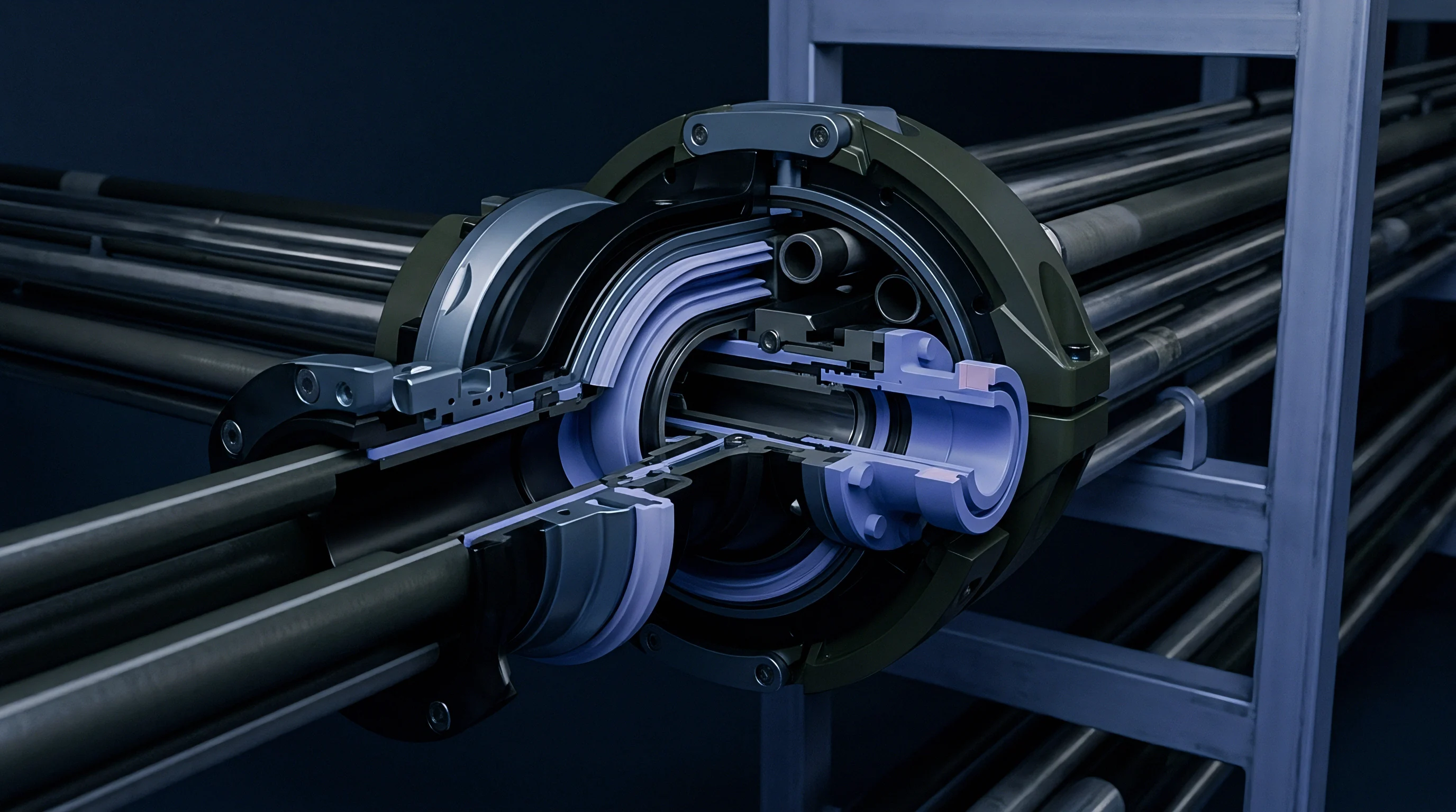
Worked Cost Comparison across Tooling Architectures
To quantify the commercial implications of managing weld line degradation, consider an automotive cooling distribution manifold specified in 35 percent glass-filled PA66. The annual production volume stands at 250,000 units across a five-year lifecycle, requiring a total production run of 1,250,000 components. The component operates under cyclic internal pressure (0 to 4.5 bar at 0.5 Hz) and fluctuating coolant temperatures (-30 to 125 degrees Celsius).
Option 1 uses a conventional two-cavity cold-runner tool with two direct sprue gates, producing a severe structural weld line along the central mounting bracket and fluid conduit. Option 2 implements a two-cavity hot-runner system equipped with sequential valve gating, eliminating the weld line completely. Option 3 utilizes a single-cavity tool operating a dynamic variotherm cycle to maximize interfacial strength while retaining standard dual gating.
- Option 1 Conventional Dual Gating requires an initial tool investment of 65,000 USD, operating on a 28-second cycle time at an hourly press rate of 85 USD, yielding an unburdened part manufacturing cost of 1.65 USD and an amortized tooling cost of 0.052 USD per part. Field warranty reserves must be capitalized at 0.45 USD per part based on an actuarial 1.8 percent weld line fatigue failure rate across 100,000 vehicle kilometers. Total landed cost equals 2.152 USD per component.
- Option 2 Sequential Valve Gating demands a tooling commitment of 105,000 USD including SVG hydraulic manifold controls, running at a 26-second cycle time on a slightly larger press frame at 92 USD per hour. The piece production cost drops to 1.66 USD due to cycle time savings, with an amortized tooling cost of 0.084 USD per unit. Field warranty reserves drop to 0.02 USD per part based on near-zero structural fatigue failures. Total landed cost equals 1.764 USD per component.
- Option 3 Variotherm Dual Gating involves a tooling investment of 92,000 USD with integrated rapid-cycling water manifolds, but cycle times inflate to 35 seconds, running at an hourly press rate of 98 USD. Part manufacturing cost rises to 2.38 USD, with an amortized tool cost of 0.074 USD per unit and warranty reserves set at 0.08 USD per part based on an estimated 0.3 percent failure rate. Total landed cost equals 2.534 USD per component.
Sequential valve gating delivers a net landed cost savings of 0.388 USD per component compared to the conventional tooling route, generating 485,000 USD in total lifecycle savings across the 1,250,000 unit contract. The 40,000 USD premium in initial tool design pays for itself within the first 105,000 parts produced. Sourcing desks that focus exclusively on initial capital expenditure select Option 1, unknowingly saddling the organization with massive downstream warranty liabilities.
When drafting tooling purchase contracts, buyers must establish clear structural accountability clauses. The quotation must specify whether the toolmaker or the part designer owns weld line placement. Suppliers commonly include standard terms stating that weld line locations remain a natural outcome of customer part geometry and gate locations, disclaiming liability for structural degradation under multi-axial fatigue.
The buyer must counter with an unambiguous contractual standard, mandating that the supplier guarantee minimum mechanical fatigue properties at all weld interfaces as verified under ISO 13003 or ASTM D7774 testing regimes.
Tool transfer clauses require identical scrutiny. If a supplier fails to maintain stable process parameters—such as dropping mold temperatures to shave cycle seconds or increasing regrind content beyond 15 percent—the degradation kinetics of the weld lines accelerate exponentially. Tool ownership documentation must allow immediate extraction of the mold without financial penalties if press-side audits reveal process parameter drift exceeding specified statistical process control limits (Cpk greater than 1.67 on peak cavity pressure and melt temperature).
A buyer who fails to tie tool transfer rights to weld line integrity loses both their capital asset and their product warranty defence when fatigue cracks inevitably appear in the field.