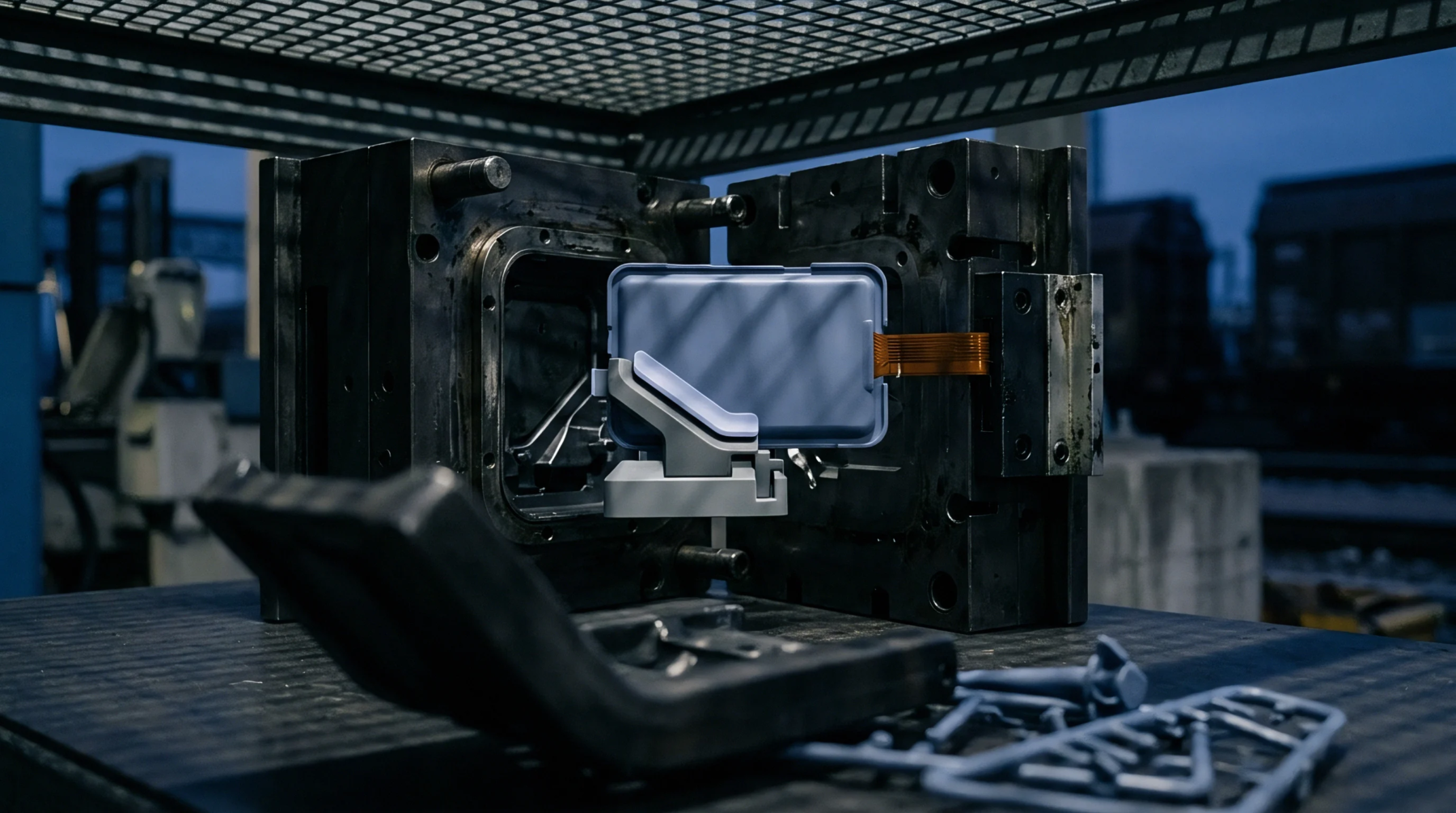
Meaning
Solid cylindrical or rectangular ground-steel columns installed between mould plates absorb and transfer high clamping tonnages across interior empty spaces. A support pillar bridges the open clearance space within the mould ejector housing, transferring immense clamp and injection forces directly from the bottom cavity retainer plate through to the rear clamping platen. Without these structural columns, mould base clamping forces would bridge exclusively across external steel rails, leaving the central cavity area unsupported and prone to elastic sagging.
The component operates entirely as a structural load-bearing member within the mould tool housing, having no direct contact with the polymer melt stream, moving ejector plates, or active cooling channels.
Deflection Resistance
Extreme hydraulic clamp pressures applied during moulding concentrate massive bending moments across unsupported cavity areas. When a mould lacks an adequate support pillar network, central core plates deflect several hundredths of a millimetre under full tonnage. This microscopic flexure causes immediate part dimensional variations, erratic wall thickness across multi-cavity layouts, and parting line flash around core pockets.
Positioning ground support pillars directly beneath high-pressure cavity positions arrests this mechanical sag, ensuring core plates remain flat and parallel throughout continuous production runs.
Tooling Assembly
Precision manufacturing of these load-bearing pillars dictates how evenly mechanical clamping stresses distribute across the mould base. Pillars must be ground to overall lengths matching adjacent spacer blocks with extreme precision, typically within ten micrometres. If a support pillar is ground slightly too long, it focalises the entire machine clamping force onto a single narrow footprint, bowing the cavity plate upward and crushing internal parting lines.
Conversely, if a pillar is ground short, it remains completely unloaded until the mould base plates have already suffered significant elastic deflection, defeating its intended structural role. Toolmakers securely bolt these pillars to the clamp plate, passing them through clearance holes machined through moving ejector plates without impeding mechanical part ejection strokes.
Platen Preservation
Correct pillar distribution extends the working operating life of expensive mould assemblies and machine platens alike. Unbalanced cavity pressures warp mould steel, accelerating wear on guide bushings, leader pins, and side-action slides. Strategic pillar placement neutralizes internal plate bending moments, distributing loads uniformly back into the machine platens.
Standardising pillar locations across modular mould designs reduces base plate thickness requirements, saving raw tool steel costs while keeping total tool stack height within specified machine open daylight envelopes.