Cross Site Gauge Reproducibility Metrics for Contoured Molded Part Support Nests
Cross-site gauge reproducibility requires kinematic 3-2-1 nests with matched thermal expansion to keep measurement variation under ten percent of tolerance.
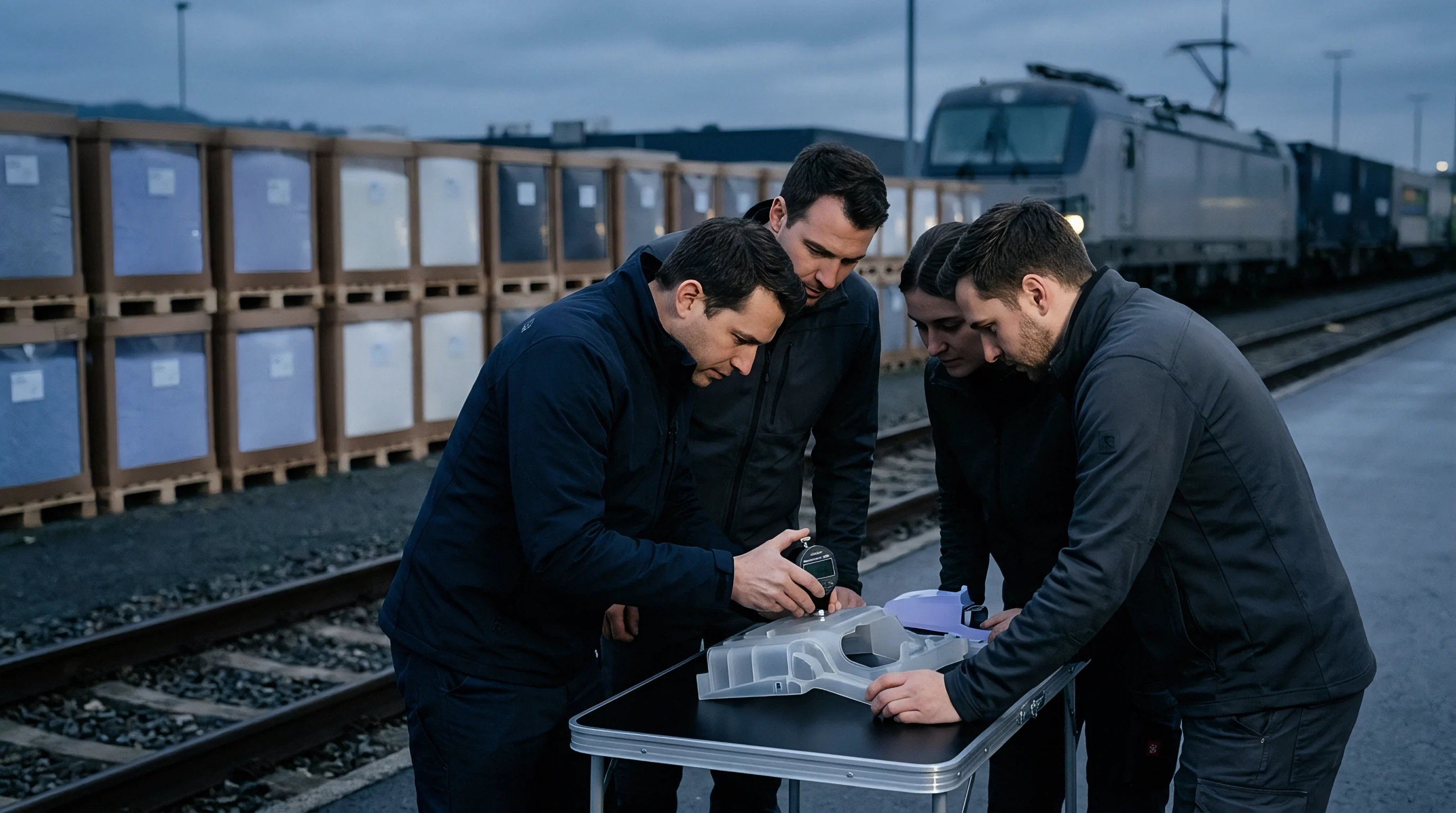

Fixture
Precision inspection of flexible polymer components relies on constraining six degrees of freedom without imparting secondary stress into thin-walled features. Molded plastic parts undergo complex volumetric shrinkage during cooling, resulting in localized warp, springback, and residual stress distributions that shift when extracted from the tool cavity. Placing a contoured molding into a metrology nest forces the elastomeric or semi-rigid polymer geometry against fixed reference locators.
If the support nest geometry fails to match the part parting line and curvature, clamping forces deform the molding, generating artificial dimensional measurements that do not reflect true part state.
Establishing an exact three-two-one kinematic constraint framework prevents over-constraining the flexible workpiece. Primary datum planes require three widely spaced contact points on the rigid surfaces of the molding. Secondary datum features utilize two locating points to arrest planar rotation, while the tertiary datum uses a single point to set linear positioning.
Steel holds shape. When support nests attempt to contact continuous contoured surfaces using fully conforming cavity blocks, microscopic variation in part wall thickness creates variable contact pressure. Localized high spots force the part off its nominal plane, distorting downstream coordinate measuring machine readings across different plant locations.
Rigid support pins locate contoured moldings without inducing elastic deformation during probing cycles.

Kinematic Location Mechanics for Thin Walled Moldings
Supporting a contoured plastic surface demands isolating structural stiffness from clamping deformation. Injected resins such as polypropylene, acrylonitrile butadiene styrene, and polybutylene terephthalate exhibit low elastic moduli compared to aluminum or steel fixture bodies. Deflection masks defect.
When an automated clamp presses a contoured flange onto a continuous epoxy support bed, variations in part thickness induce bending moments across adjacent unconstrained walls.
Positioning accuracy improves when contoured nests substitute continuous contact for discrete, adjustable spherical locators. Spherical contact tips minimize friction and establish point contact exactly at specified datum target locations defined on the engineering drawing. Unclamped resin springback distorts readings.
Isolating datum targets to localized spherical pins ensures that thermal distortion or wall thickness variation across injection molding lots does not alter the fundamental coordinate system setup.

Nest Deflection and Structural Compliance Criteria
Polymer support housings subjected to localized point loads deform during contact measurement cycles. Support nests constructed from tooling board, filled epoxy resins, or 3D-printed photopolymers lack long-term structural modulus and exhibit creep under continuous clamping force. Over extended measurement campaigns, localized pin seats compress, introducing dimensional drift into metrology data.
High-volume inspection fixtures require hardened steel or carbide rest pads mounted inside CNC-machined 6061-T6 aluminum or 316 stainless steel fixture bases. Material selection directly influences structural deflection under clamp loads. Aluminum bases offer lightweight handling for manual bench inspections but require thermal stabilization in temperature-controlled quality assurance laboratories.
Stainless steel bases provide superior mechanical damping and match the thermal expansion characteristics of coordinate measuring machine granite tables more closely.
Designing nest locators for complex contoured parts demands systematic evaluation of potential mechanical failure modes across multi-site manufacturing environments:
- Over-Constrained Datum Contact occurs when continuous conforming nest surfaces trap local wall thickness surges, forcing the molding to rock or twist during clamping.
- Resin Springback Deformation develops when high clamping forces flatten natural part curvature, yielding false pass readings on CMM inspection reports while masking true tool warp.
- Asymmetrical Clamping Torque happens when manual toggle latches apply uneven downward forces across opposite support pins, bending thin-walled features prior to stylus contact.
- Wear at Primary Contact Spheres results from repeated loading of abrasive glass-filled resins, abrading locating pin tips and lowering part orientation relative to absolute machine coordinates.
Matching fixture stiffness directly to part nominal wall thickness prevents false structural deflections during inspection.
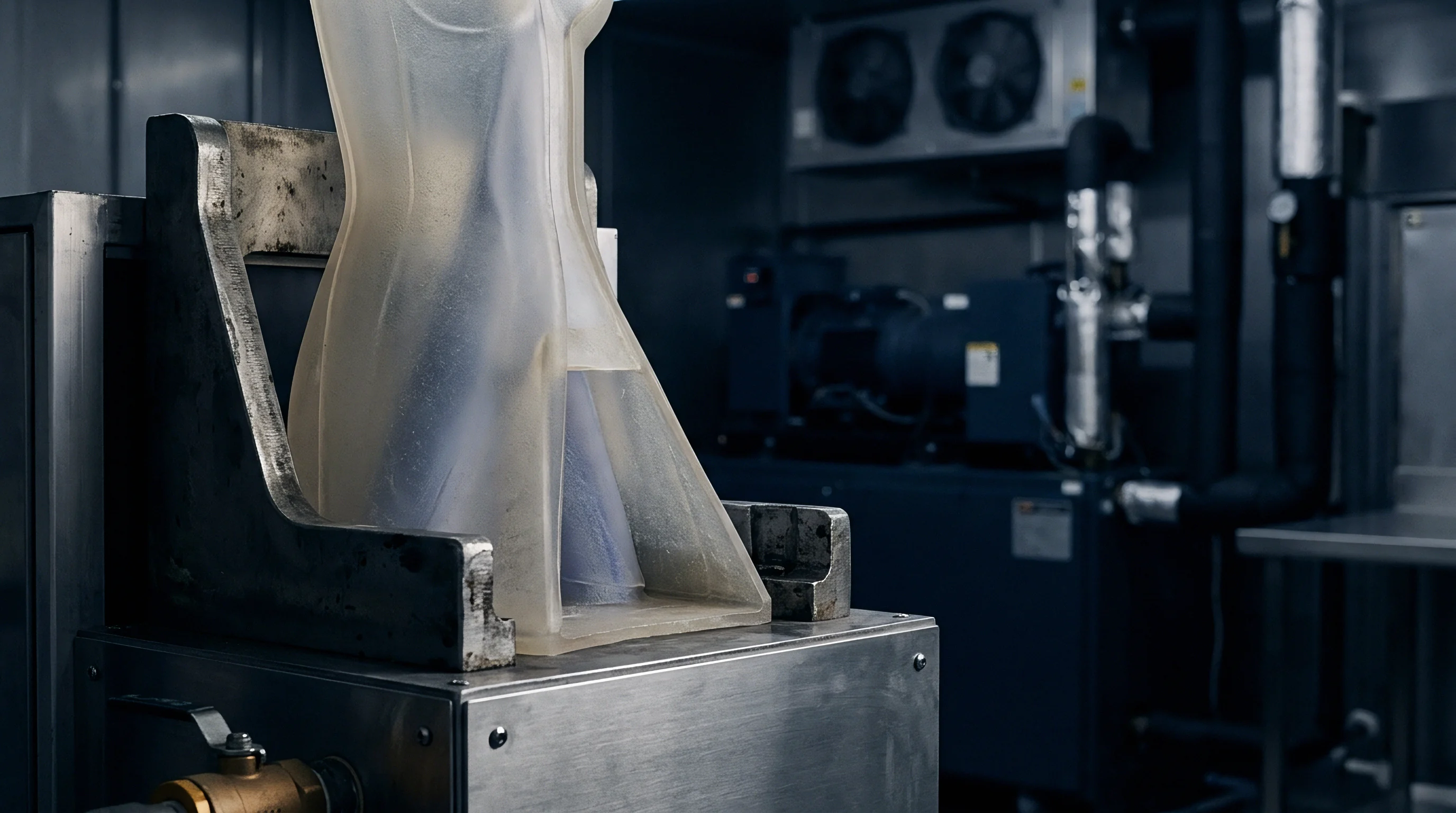

Contact
Stylus touch forces during coordinate metrology alter physical dimensions on low-durometer resin surfaces. Trigger forces on conventional tactile CMM probes range between point zero five and point two newtons. While negligible when inspecting machined steel, a point one newton point force applied to an unsupported two-millimeter polypropylene wall induces elastic deflection exceeding fifteen micrometers.
This physical displacement registers as actual material variance, inflating measurement system error metrics.
Probing force creates error. Mitigating contact deformation requires backing contoured inspection points with rigid support pins located directly opposing the probe vector. When geometric constraints prevent placing opposing pins, optical scanning or low-force analogue contact probes provide necessary measurement fidelity.
Non-contact laser line scanners eliminate touch deformation entirely but introduce surface reflectivity and ambient lighting variables that require strict calibration across multiple manufacturing facilities.

Elastomeric Interface Pads versus Hardened Tool Steel
Selecting nest cladding materials demands balancing localized point pressures against abrasion resistance during high-volume inspection cycles. Unfilled thermoplastic parts show visible surface scratching when loaded against hardened tool steel locator pins repeatedly. Quality standards for automotive interior trim and optical lens housings prohibit contact marks on visible aesthetic surfaces.
Elastomeric pads, polyurethane inserts, and polyether ether ketone locators soften point contact, preventing surface blemishes on delicate plastic parts. Elastomeric materials introduce mechanical compliance into the gauge stack-up. Under clamping pressure, elastomeric pads compress non-linearly, shifting part position dynamically during measurement sequences.
Hardened steel locators coated with titanium nitride offer low friction and extreme wear resistance without compromising kinematic rigidity.
| Locator Material Type | Young Modulus (GPa) | Shore Hardness | Deflection Under 0.5N Load (um) | Aesthetic Scratch Risk |
|---|---|---|---|---|
| Hardened Tool Steel (D2) | 210 | 62 HRC | 0.02 | High |
| Titanium Nitride Coated Steel | 250 | 70 HRC | 0.01 | Moderate |
| Polyether Ether Ketone (PEEK) | 3.6 | 85 Shore D | 0.85 | Low |
| Cast Polyurethane Overlay | 0.05 | 70 Shore A | 14.20 | Zero |

Clamping Force Actuation and Restraint Dynamics
Pneumatic toggle hold-downs apply repeatable downward loads when calibrated using inline pressure regulators. Manual hand-clamp fixtures depend entirely on operator technique, introducing operator-to-operator variance into Gage Repeatability and Reproducibility studies. An operator applying excessive latching torque bows the center section of a contoured plastic panel, shifting peripheral feature coordinates by tenths of a millimeter.
Automated clamping schemes utilize proportional pneumatic actuators regulated to specific force limits. Light-duty sensors monitor clamp engagement, ensuring that pneumatic cylinders complete their full stroke before CMM inspection routines commence. Integrating load cells under primary locator pins provides real-time verification of clamping force, confirming that resting force stays within specified operating windows across production sites.
Selection of support nest contact interfaces and clamping mechanics follows strict functional guidelines:
- Hardened Tool Steel Contacts provide maximum kinematic stability and zero measurable deflection, making them standard for non-aesthetic industrial moldings and internal structural components.
- Polyether Ether Ketone Elements deliver moderate mechanical rigidity while protecting soft, high-gloss thermoplastic surfaces from localized scratching and galling.
- Cast Polyurethane Overlays cushion fragile thin-gauge thermoformed parts but require continuous monitoring due to non-linear creep and environmental moisture absorption.
- Anodized Aluminum Housings provide high thermal conductivity and lightweight handling, though wear pads must protect steel pin mounting threads from stripping.
Toolmakers frequently claim that localized part warping stems entirely from resin batch variance rather than fixture support pin misalignment.

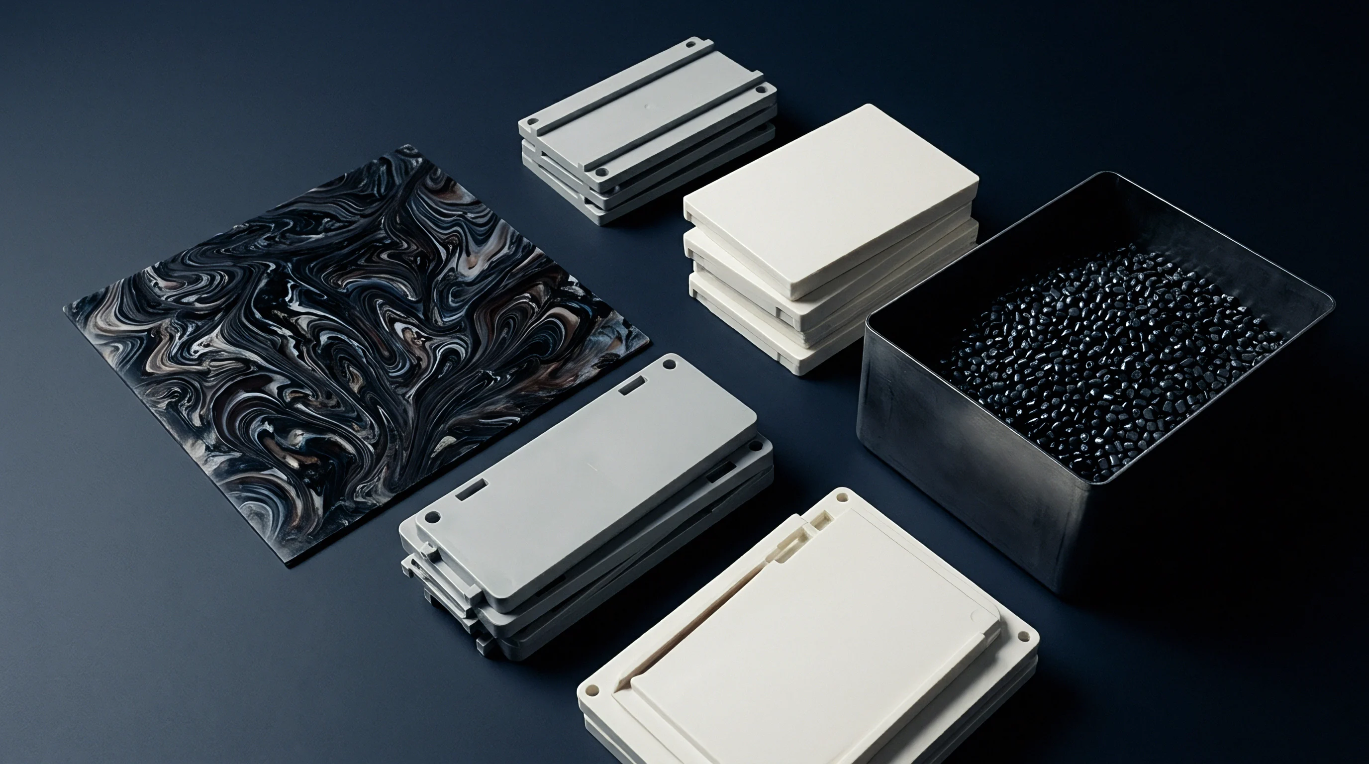
Transfer
Transporting measurement tooling between molding plants introduces dimensional drift driven by thermal gradients and mechanical settling. Coordinate quality assurance relies on comparing part dimensions against engineering CAD models across global manufacturing networks. A support nest calibrated in a climate-controlled European metrology laboratory at twenty degrees Celsius exhibits physical dimensional expansion when installed in a tropical production facility operating at twenty-eight degrees Celsius.
Thermal expansion shifts datums. Coefficient of thermal expansion mismatches between aluminum fixture bases, steel locating pins, and polymer moldings generate linear dimensional offsets. Aluminum expands at approximately twenty-three micrometers per meter per degree Celsius.
Over a one-meter support nest base, an eight-degree temperature differential induces nearly two hundred micrometers of expansion, consuming a massive portion of tight injection molding tolerance bands.
Thermal variations exceeding two degrees Celsius between site laboratories alter aluminum fixture dimensions by twenty-three micrometers per meter.
How Does Thermal Expansion Distort Cross Site Nest Repeatability?
Temperature differentials of five degrees Celsius between manufacturing floors shift coordinate datum targets significantly. Polymer parts exhibit thermal expansion coefficients five to ten times greater than metallic support fixtures. A glass-filled nylon part expands differently than its supporting aluminum nest, causing datum locating pins to bind inside molding target holes or gap away from reference rib surfaces.
Mitigating cross-site thermal distortion requires enforcing strict environmental soak protocols prior to measurement. Support nests and plastic production samples must acclimate in the CMM room environment for a minimum of four hours before running inspection routines. Advanced metrology software applies dynamic thermal compensation algorithms, adjusting measured coordinates based on real-time temperature sensors attached directly to the aluminum fixture frame and the plastic workpiece.
Interchangeability Verification across Automated Coordinate Measuring Machines
Machine table flatness variations and probe head calibration differences cause systemic offsets when measuring identical plastic parts. Transferring a contoured support nest from a bridge-type CMM utilizing a tactile star probe to a horizontal-arm CMM with an optical line scanner alters observed feature positions. Sensor calibration master artifacts must tie back to international traceability standards to isolate machine bias from nest bias.
Temperature shifts steel dimensions. Cross-site transfer qualification requires shipping a set of stable master parts along with the physical nest. These golden parts, manufactured from carbon-fiber reinforced polymer or invar alloys, remain geometrically invariant across normal environmental ranges.
Measuring golden parts at both originating and receiving facilities isolates coordinate measuring machine calibration errors from structural fixture deformation incurred during transit.
Ignoring environmental equilibrium during cross-site fixture handoffs results in rejected shipments and unrecoverable freight expenses.
Metrics
Quantifying measurement system capability across multiple facilities demands evaluating variance contributions from operators, environments, and mechanical nests. Measurement System Analysis relies on statistical breakdown of total observed variance into distinct sub-components. Total variance equals part-to-part variance plus measurement system variance.
Gauge Repeatability and Reproducibility studies isolate equipment variation from appraiser variation across testing locations.
Operators introduce observational variance. Gauge metrics isolate variance. Evaluating contoured support nests across cross-site production networks requires executing two-way Analysis of Variance statistical designs.
ANOVA methods separate main effects—such as part geometry variation and site locations—from interaction effects, including operator-by-part and site-by-fixture interactions. A high interaction variance indicates that the support nest performs inconsistently depending on local operator clamping habits or specific machine table setups.
ISO 22514 standards mandate total measurement variation below ten percent of tolerance for production tool sign-off.

Two Way Analysis of Variance for Multi Facility Gauges
Statistical partitioning separates total observed spread into distinct components attributed to part geometry, site-specific operators, and fixture interaction terms. Standard Gauge R&R metrics report equipment variation, representing repeatability, and appraiser variation, representing reproducibility. When evaluating cross-site reproducibility, site location becomes an additional variance component in the ANOVA model.
The total study variation percentage calculates by comparing the measurement system standard deviation against total process standard deviation or drawing tolerance width. A Percent Gauge R&R value below ten percent signifies an acceptable measurement system. Values between ten and thirty percent indicate marginal capability, requiring engineering review based on feature criticality.
Values exceeding thirty percent indicate unacceptable measurement system performance, rendering the support nest incapable of discriminating between good and bad molded parts.
Worked Mathematical Case for Cross Site Gauge Variance
Consider ten contoured automotive door trim samples measured across three manufacturing sites by three operators per facility using identical support bases. Each operator measures each part twice, generating one hundred eighty total data points for a critical contour position feature with a specification tolerance width of two millimeters.
Data proves capability. Mathematical analysis partitions total sum of squares into constituent variance components: Part Variance, Site Variance, Operator within Site Variance, Part-by-Site Interaction Variance, and Equipment Repeatability Error Variance.
- Select ten representative molded parts spanning the full range of process variation, including minimum, nominal, and maximum material conditions.
- Transport the ten parts and the master contoured support nest to Facility A, acclimating all equipment in the metrology laboratory for six hours at twenty degrees Celsius.
- Instruct three trained metrology technicians at Facility A to independently clamp and measure each part twice in randomized sequence using a calibrated tactile CMM.
- Ship the master parts and support nest to Facility B and Facility C, repeating identical randomized measurement sequences with three local operators at each site.
- Compile coordinate dataset into a nested three-factor ANOVA model to extract individual variance components and compute the Number of Distinct Categories.
| Source of Variance | Sum of Squares | Degrees of Freedom | Mean Square | Variance Component | % Contribution to Total |
|---|---|---|---|---|---|
| Part-to-Part | 14.8520 | 9 | 1.6502 | 0.09120 | 84.12% |
| Site Location | 0.4210 | 2 | 0.2105 | 0.00310 | 2.86% |
| Operator (Site) | 0.1840 | 6 | 0.0307 | 0.00085 | 0.78% |
| Part x Site | 0.3120 | 18 | 0.0173 | 0.00215 | 1.98% |
| Repeatability (Equipment) | 0.7920 | 144 | 0.0055 | 0.00550 | 5.07% |
| Total Variation | 16.5610 | 179 | — | 0.10842 | 100.00% |
Calculating percent study variation yields a total Gauge R&R of thirteen point eight percent of process variation, consuming nine point four percent of specified design tolerance width. The calculated Number of Distinct Categories equals nine. An NDC value of five or greater confirms that the cross-site measurement system successfully distinguishes distinct part variation categories across facilities without being masked by nest repeatability or operator clamping differences.
ISO 22514 Annex B specifies that interaction terms exceeding ten percent of total study variance invalidate gauge transfer approval between facilities.


Calibration
Establishing physical traceability demands master artifacts manufactured from low thermal expansion materials. Support nests undergo mechanical wear, fastener loosening, and structural alignment drift during routine plant use. Periodic calibration confirms that primary locator pins, clamping rest surfaces, and datum target blocks maintain their certified spatial coordinates within defined metrology limits.
Master artifacts establish truth. Optical or tactile verification routines measure support nests directly against high-precision calibration masters. Invar calibration frames, manufactured with zero thermal expansion characteristics, feature micro-etched reference targets matching the exact nominal XYZ coordinates of the part drawing datum points.
Mounting the calibration master onto the support nest identifies mechanical pin wear prior to inspecting production resin moldings.
Tactile coordinate measuring machines detect localized part wall sink when probe trigger forces exceed point one newtons.
Master Artifact Sourcing and Thermal Stability Guidelines
Invar spheres and carbon-fiber master templates provide invariant reference points for routine coordinate machine verification. Machined metallic artifacts require optical polishing and sub-micrometer coordinate certification in accredited secondary calibration laboratories. Storing master artifacts inside protective, climate-controlled cases prevents corrosion and mechanical shock from damaging reference surfaces.
Wear degrades precision. Metal-to-metal contact between master artifacts and support nest pins causes localized burnishing over extended calibration cycles. Tooling engineers apply hardened diamond-like carbon coatings to calibration artifact contact points, preserving sub-micrometer dimensional fidelity over thousands of verification cycles.
Gauge Capability Index and Bias Assessment
Calculating Cgk evaluates both systematic error and scatter around an established reference standard. Gauge capability metrics focus on fixture precision and accuracy relative to target reference values, excluding part-to-part production variation. A master artifact measured fifty consecutive times in a support nest yields the mean measured value and standard deviation.
Systematic bias represents the absolute difference between the mean measured dimension and the certified reference artifact dimension. The Cgk capability index incorporates both bias and measurement scatter relative to user-defined tolerance bands. A Cgk value equal to or exceeding one point three three confirms that the mechanical support nest exhibits acceptable precision and accuracy for production quality control.
Cross-site qualification requirements necessitate assembling standardized documentation dossiers for quality audit compliance:
- Kinematic Scheme Engineering Drawings define exact 3-2-1 locator coordinates, pin radii, clamp vector force limits, and required datum target land areas.
- Master Artifact Calibration Certificates provide NIST-traceable dimensional verification data for reference spheres and invar alignment master frames.
- Cross Site Temperature Log Records document ambient laboratory temperature, relative humidity, and thermal soak times during Gage R&R execution.
- ANOVA Gauge Variance Reports detail statistical variance breakdowns, Percent Gauge R&R calculations, and calculated Number of Distinct Categories.
Whether optical scanning lines match tactile stylus probing on non-rigid contoured surfaces remains a subject of ongoing industry debate.
Protocol
Formalizing cross-site measurement agreements prevents commercial disputes over out-of-spec part rejections during production ramp phases. Sourcing contracts between Tier 1 automotive suppliers and OEM molding facilities specify binding quality verification protocols. When receiving plants reject production lots based on internal CMM inspections while sending plants claim parts meet print specifications, the dispute frequently traces back to mismatched support nest designs or differing clamping sequence protocols.
Sourcing contracts lock specifications. Tooling quotes lock responsibility. Standardizing metrology fixture drawings early in the tool design cycle ensures that primary tooling vendors and production receiving sites build identical support nests.
Engineering prints must mandate identical locator pin materials, clamping actuation pressures, CMM stylus tip diameters, and software alignment algorithms across all global manufacturing facilities.
Drawing Callouts for Metrology Fixture Alignment
Engineering prints specify reference datum target zones matching physical nest resting surfaces precisely. Geometric Dimensioning and Tolerancing callouts according to ASME Y14.5 or ISO 1101 dictate how support fixtures locate flexible parts. Datum target symbols specify spherical point contacts, planar land areas, or line contacts using exact target coordinates and area dimensions.
Clamping order alters dimensions. Drawing notes must explicitly state the sequential clamping order for manual or automated hold-downs. Primary datum clamps engage first to seat the molding against the three-point primary plane.
Secondary clamps actuate second, pulling the part against line locators without lifting the part off primary rest pins. Tertiary clamps engage last, locking linear position without bending thin-walled flanges.
Dossier Requirements for Production Tooling Sign Off
Supplier quality approval demands complete documentation proving measurement variance consumes under fifteen percent of total design tolerance. Prior to authorizing commercial production tool release, the molding facility submits a complete gauge qualification dossier. This dossier includes CMM calibration records, fixture coordinate inspection sheets, cross-site Gage R&R statistical output, and physical surface scratch evaluations on aesthetic part faces.
Cross-border sourcing practices write strict fixture handover clauses into procurement contracts. Ownership of production tooling transfers only after the receiving facility executes an independent Gage R&R study matching the originating toolroom results within agreed statistical thresholds. Standardized protocols eliminate measurement system ambiguity, ensuring that plastic moldings produced on one continent install seamlessly into assemblies built on another.
Enforcing identical datum clamping sequence notes on master drawings locks process capability metrics across international supply chains.